Many questions implied in those posts. ")
Zobel networks are at best an approximation. For sure they correct impedance when correctly calculated. This estimate is as good as most:
Impedance Equalization (L-Pad) Circuit Designer / Calculator
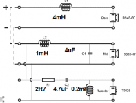
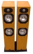
When you build a time-aligned speaker, which looks like this, you generally find that second order filters work best on bass and treble.:
However, with a flat baffle, you need to delay the treble response so that the bass aligns well. This is done by adding a first order element which is pure delay to the tweeter. This is the expensive 3rd. Order Butterworth filter. Expensive because it needs a large (ca. 15uF) capacitor after the 2nd order element. It has a benefit of increased slope which helps the tweeter work well at the Fs resonance.
Mathematically it is a beautiful filter with hexagonal symettry and some relation to atomic orbitals in Quantum Mechanics. Trust me on this, 3rd. Order is right here for the optimum result.
We are, after all, PROFESSIONALS.
Zobel networks are at best an approximation. For sure they correct impedance when correctly calculated. This estimate is as good as most:
Impedance Equalization (L-Pad) Circuit Designer / Calculator
When you build a time-aligned speaker, which looks like this, you generally find that second order filters work best on bass and treble.:
An externally hosted image should be here but it was not working when we last tested it.
However, with a flat baffle, you need to delay the treble response so that the bass aligns well. This is done by adding a first order element which is pure delay to the tweeter. This is the expensive 3rd. Order Butterworth filter. Expensive because it needs a large (ca. 15uF) capacitor after the 2nd order element. It has a benefit of increased slope which helps the tweeter work well at the Fs resonance.
Mathematically it is a beautiful filter with hexagonal symettry and some relation to atomic orbitals in Quantum Mechanics. Trust me on this, 3rd. Order is right here for the optimum result.
An externally hosted image should be here but it was not working when we last tested it.
We are, after all, PROFESSIONALS.
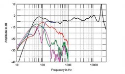
Oh, I missed the question about the standard 27kHz resonance of aluminium dome tweeters. Modern domes are made with with all sorts of materials on the surround. This modifies the characteristic resonant frequency of metal tweeters.
It is also common to use aircraft-grade Titanium, which is also different. Anodizing tweeters with a stiff oxide coating also causes changes. The theory is that all this stuff is supersonic, but in my experience, you hear the characteristic signature of metal in the harmonic output. The fact is that drivers and cabinets sound like what they are made of.
It is also common to use aircraft-grade Titanium, which is also different. Anodizing tweeters with a stiff oxide coating also causes changes. The theory is that all this stuff is supersonic, but in my experience, you hear the characteristic signature of metal in the harmonic output. The fact is that drivers and cabinets sound like what they are made of.
Last edited:
Good evening, Steve. Once more i appreciate your time and knowledge sharing to clarify some of my immense doubts. Thank you very much.
Its noticeable that you are very comfortable with loudspeakers projects; most probably you work in the field.
Unfortunately i dont have a degree in electronics. It was my option, so i try to learn it gently.
I can get two MKP caps with 15uF/250V, by € 20,00 with delivery. The doubt is: Does it returns the investment in sound quality terms with the original HF drives?
A notice about the MA Silver S6: It have two reflex ports at the rear side. One at the bottom and one at the top. People should try it with the provided plugs, before "hammering" the "Xover".
Another question is: Do the SEAS Exotic w8t35 project worth the investment?
Best regards
Paulo

PALUSE, the question was how to improve the Monitor Audio loudspeaker. I have done that for you with some crossover tweaks. It will cost money, and you may even prefer the rougher original design which doubtless has some immediate impact. Since it is a 1000 Euro speaker, I don't think 20 Euros for capacitors is disproportionate. This is DIY, and you either are into it or not.
The SEAS Exotic W8 project is a nice one. 2000 Euros on drivers is rather a lot, but they do look fun in the high efficiency bracket. This sort of speaker has an enthusiastic following among valve users, and DeVore make something in this style with the Orangutan.
I might fancy a more affordable SEAS ER18RNX with a slightly different filter and an Excel tweeter, but no question those SEAS exotic drivers are works of art and state of the art!
For time being, its with the Zobel (8,2 Ohms+1uF), and the original mid drive 4uF PP cap is cleaning the top band of the low drive; in prallel with the drive!
For my surprise, it delivers a more confortable listening and depth of the soundstage. Treble is more comfortable present. A new step to evaluate.
The final and definitive upgrade have to wait... I decide to go all the way, when i can expend all the cash. The 2mH inductors with 0,29Ohms are damn expensive.
One step at the time...
Bye...

Am I Crazy?
So how expensive are they vs a new speaker(s) purchase? I think the basic premise is that these are worth putting money into as original build quality was good but cheap parts starting a degradation slide is contributing to the deteriorating sonics.
I'm considering pumping $400-$500 in upgrades to these (rs6) Am I CRAZY????
A review of the Monitor Audio Silver 6S let me doubt about the crossover modification in the midrange:
Audio Ideas Guide Hi-Fi and Home Theater Equipment Reviews: Monitor Audio Silver 6S
The frequency response shows an early roll-off starting at 1 kHz. Increasing the coil and the capacitor, as Steve suggests, will make things only worse.
Audio Ideas Guide Hi-Fi and Home Theater Equipment Reviews: Monitor Audio Silver 6S
The frequency response shows an early roll-off starting at 1 kHz. Increasing the coil and the capacitor, as Steve suggests, will make things only worse.
Do you have any better suggestions?A review of the Monitor Audio Silver 6S let me doubt about the crossover modification in the midrange:
Audio Ideas Guide Hi-Fi and Home Theater Equipment Reviews: Monitor Audio Silver 6S
The frequency response shows an early roll-off starting at 1 kHz. Increasing the coil and the capacitor, as Steve suggests, will make things only worse.
I can only reiterate what I have done and why I did it. Firstly I attempted to reduce the cone breakup from the metal woofers. This should make for a smoother sound without metal harshness.
Secondly I attempted to smooth out the midrange dip at 3kHz. This needed a 3rd order filter and the bigger bass coil.
Lastly I attempted to reduce the top end a little. This needs the Zobel.
It's worth mentioning that an expensive 0.3R coil is really not needed. About 0.8R would doubtless be fine. The 15uF capacitor can be lost with a return close to the original tweeter filter and a better phase response. There is nothing stopping you reducing the input resistor to the tweeter filter to 1.5R for more treble level, as long as you are aware you stress the tweeter more.
It's a shame AllenB no longer posts here. I can understand his reasons. People here make awfully hard work of what should be a fun hobby.
Attachments

Do you have any better suggestions?
Sorry, no. The driver parameters are completely unknown. I don't think it's correct to assume Visaton AL130 and DSM25 would be similar. Obviously drivers and/or crossover of S6 and RS6 are also different.
In the case of the S6, an elliptic filter might give more spl in the upper midrange and suppress the cone break-up as well. But it's impossible to design the filter without having any driver data.
Still Crazy
So if we're concerned about the validity of the modeling, a path forward might be to retain the basic X-over design and simply substitute better quality caps and resistors with the expectation that "harshness" and spatiallity focus would improve. This has certainly been reported with this type of mods to Polks & Def Tech which are in a similar price/ market as the M.A. S6/RS6 and had similar upgrade goals. By the way, what is the difference between the two?(S6,RS6) I've been assuming, good for one would apply to both.
So if we're concerned about the validity of the modeling, a path forward might be to retain the basic X-over design and simply substitute better quality caps and resistors with the expectation that "harshness" and spatiallity focus would improve. This has certainly been reported with this type of mods to Polks & Def Tech which are in a similar price/ market as the M.A. S6/RS6 and had similar upgrade goals. By the way, what is the difference between the two?(S6,RS6) I've been assuming, good for one would apply to both.
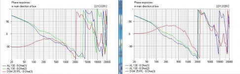
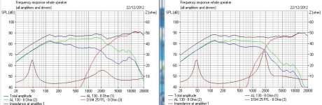
@dunenthem. I'm not AT ALL concerned about the accuracy of the modelling. Within certain limitations, I found it worked EXACTLY, as shown below!
As it goes, Monitor Audio have employed decent components. What they have done is cut down the number, which we might rectify.
Dissi, don't take this too hard, but most people wouldn't know an elliptic filter if it slapped them in the face, although it happens I do know what one is. Please do not employ such vague audio-gibberish. Leave that to Zaph...
We are living in the real world. It IS possible to modify a crossover VERY PREDICTABLY with enough insight into filters and metal drivers. Naturally there is an element of trial and error here AND reporting back with the results. But I have, I hope, addressed the three main criticisms of the listening experience. I have also been quite conservative in changes and reused components as much as possible. Time will tell.
As it goes, Monitor Audio have employed decent components. What they have done is cut down the number, which we might rectify.
Sorry, no. The driver parameters are completely unknown. I don't think it's correct to assume Visaton AL130 and DSM25 would be similar. Obviously drivers and/or crossover of S6 and RS6 are also different.
In the case of the S6, an elliptic filter might give more spl in the upper midrange and suppress the cone break-up as well. But it's impossible to design the filter without having any driver data.
Dissi, don't take this too hard, but most people wouldn't know an elliptic filter if it slapped them in the face, although it happens I do know what one is. Please do not employ such vague audio-gibberish. Leave that to Zaph...
We are living in the real world. It IS possible to modify a crossover VERY PREDICTABLY with enough insight into filters and metal drivers. Naturally there is an element of trial and error here AND reporting back with the results. But I have, I hope, addressed the three main criticisms of the listening experience. I have also been quite conservative in changes and reused components as much as possible. Time will tell.
Attachments
conferm 22 ohm parallel to tweeter rs6
i did the 22 ohm parallel to the tweeter mod and can confirm this worked very very well actually! i used a 10 watt resister of 22 ohm. and fits perfectly. The sound is so much better now, also the bass is more deep. dont know why. maybe only because there is less high, i dont know but the speakers are kicking *** so much now! good luck everybody with the RS6.
Hi Rob.
Thanks for the reply!
Sorry to ask again... you put a 22Ohms resistor in parallel with the tweeter?
It will stress the amplifier, because it lowers the impedance of the HF network (X_over). Its more polite for the amplifier to put the resistor in serial with the tweeter, to attenuate the signal amplitude (Voltage)!
Best regards
Paulo
i did the 22 ohm parallel to the tweeter mod and can confirm this worked very very well actually! i used a 10 watt resister of 22 ohm. and fits perfectly. The sound is so much better now, also the bass is more deep. dont know why. maybe only because there is less high, i dont know but the speakers are kicking *** so much now! good luck everybody with the RS6.
RS-6 Crossover Details
Still looking to modify my M.A RS6 crossover......I discovered that there are significant differences from the S6 discussed above. We knew that it was different based on the F.R. ascending on the stereophile measurements. Anyway, after opening up, this is what I found;
Version 2 ,RS6 scribed on the circuit board;(Stock Crossover)
,,l-----l----C1---R1---- + ,,,,Tweeter
,,l,,,,,,,l
>l,,,,,,L1
,,l,,,,,,,l
,,l-----l--------------- -
R1=7W2.2ohm
C1=6.0,250V
L1 = ? very small coil
,,l------l-------L2------ +,,,,Midwoofer
,,l,,,,,,,,l
,,l,,,,,,,C2
>l,,,,,,,,l
,,l,,,,,,,L3
,,l,,,,,,,,l
,,l------l--------------- -
L2=.8mH,
C2=4.0,100V
L3= ? ~twice the L1 coil
,,l--------L4---------- +,,,Woofer
,,l
>l
,,l
,,l-------------------- -
L4= 5.0Mh
Still too much treble, some harsh upper mid. longterm listening still an issue although much improved via tube preamp,tube cd player. I have tried routing my tube preamp out to my parasound p7 where I can use my tone controls. Typically -4 gets me to a better place on the high end but clearly the tone circuit has degraded the signal slightly.
My current thought is to try the 22 ohm across the tweeter with a 4 ohm replacement on the series resistor first. Does this approach still make sense given this crossover? I noticed they put a Zobel? on the mid woofer ,not the tweeter.
I wonder what system7 has to say regarding the evolution of S6 TO RS6. Any comments would be appreciated. By the way, where do you guys stand on bypass Caps? Any application here ?
Anybody doing a PROPER job with metal midbass cones deals with the breakup around 7kHz.
DIY-Loudspeakers
This what is called a 2.5 way. If you are interested, you can do some mods.
There's plenty of ideas in this thread. Have a go.
DIY-Loudspeakers
This what is called a 2.5 way. If you are interested, you can do some mods.
There's plenty of ideas in this thread. Have a go.
Attachments

Dazed and Confused
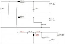
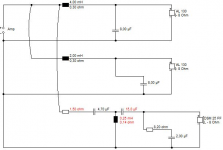
System 7 ,you lost me on this latest schematic. Re;
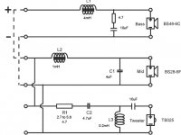
1. The Zobel is now gone on the tweeter?
2 The twin 8 mF shunt Caps have been replaced? New Zobel on the bass unit?
3. The 15mF butterworth is now a 10mF?
4. The upsized coil in mid bass is now back to 1mH?
I don't get it. What changed?
System 7 ,you lost me on this latest schematic. Re;
1. The Zobel is now gone on the tweeter?
2 The twin 8 mF shunt Caps have been replaced? New Zobel on the bass unit?
3. The 15mF butterworth is now a 10mF?
4. The upsized coil in mid bass is now back to 1mH?
I don't get it. What changed?
Why do you think for a minute that Monitor Audio, with a revolving door of staff, have really any idea what they are doing with this combination of drive units?
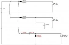
The S6 was the earliest version. IIRC, the RS6 was an adjusted crossover version. FWIW, most 5-6" basses look like this:
AL 130 - 8 Ohm
Shiny metal drivers that look good, but can it be improved soundwise? I thought so: http://www.diyaudio.com/forums/multi-way/115780-monitor-audio-s6-tweek-5.html#post3294900
I gave the basses more rolloff to reduce the 7kHz bell resonance and zobelled the tweeter and made it third order to stop it sounding so bright at the top and match slopes. Give it a go. If it's no good, come back! This is diy. It either works or it doesn't.
Attachments
Took The Leap
I decided to take a stab at improving the RS6 s. Lack of experience, measuring equipment, and 63 yr old ears have not deterred me yet. Took the schematic from system 7 as a starting point;
1. intalled the RC network on the tweeters. Used 8 ohm resistor and 2.2 mH cap
in parallel to the driver. A smoother high end resulted , very satisfied with the improvement w/o any obvious loss of valid information.
2. arranged with wires and clips to install an "outside the housing" 3rd order arrangement . Ran multiple capacitors to cover values from 13 to 19. Long story short, I have been unable to find a value that doesn't either suffer unnatural harmonics or a dramatically reduced upper midrange. The best for harmonics was 18.33 but the music was 2 dimensional with little impact compared to the original XO with the RC addition to the tweeter. I've been back and forth several times and just can't get into the 3rd order arrangement on the tweeter. It seems as if I'm losing quite a bit of depth/ spatiality and sharp edges to the HF content. It does clean up a lot of the lower HF distortion but at too much of a cost to musicality. Much too sterile for my tastes so far.
My question is, how flat is the sweet spot? I have been covering every 1/3 mH in the range mentioned earlier. I am assuming this should show an optimum if its there. I am about ready to give up on the 3rd order and focus on the midrange/woofers.
Any comments or suggestions?
There's a point in audio when anybody with an open mind admits that there is no clear answer.

According to my current thinking, a 7.5R plus 2uF Zobel (not sure if "2.2mH" cap is a typo?) across the tweeter ought to do good things. I am ready to admit that a 22R 10W wirewound resistor shunted across the tweeter might effect a similar improvement in top end smoothness.
Actually improves amplifier stability more than anything.
The next step;
At the time of my last post, I had settled on the original crossover with the addition of an R-C network across the tweeter. Wasn't able to get the 3rd order arrangement to sound better- cleaner but not better. Again , thanks to System7 for his suggestions.
Since that time , I have modified the crossovers further;
1. Removed the magnetic standoff between the binding post and the XO board. Hardwired the connection(s).
2. Removed the ORIGINAL capacitors and resisters and replaced with identical values using Mills 10 watt resisters and "new" capacitors I purchased from Jeff at Soniccraft. Rewired the runs from the XO board to the drivers for the tweeter and midrange.
3. Removed the temporary RC network across the tweeter and replaced it with a mills resister and Soniccap of identical value(s).
I am happy to report I was able to fit the new components on the existing board with the exception of the RC network which I put behind the tweeter. Pretty cramped but do-able.
I now have about 75 hours on the new crossover. Here are my thoughts at this time;
-The addition of the RC network to the original crossover was able to remove the objectionable "harsh" component to the music without removing musical content. An easy and inexpensive upgrade when installed behind the tweeter.
-The new component upgrade brought a much smoother, sweeter presentation to the music while at the same time exposed much more detail than before. The previous soundstage was wide but had the conical blare feeling at the primary listening position. After the modification ,a wall of music appeared and the soundstage was much more three dimensional. There is now an ease to the music -listening fatique is greatly reduced. I am very happy with this upgrade.
I know there are many well respected experts in the audio industry that can't hear an improvement when upgrading over stock capacitors /resistors.In MY system it was such a dramatic and obvious improvement that there must be very system specific influences at work here .
I have never attempted this type of modification before -minimal soldering experience. It wasn't complex but overall many hours of trial and error listening went into this. The actual modification took maybe 4 hours per board. I could probably do it in half the time now.
Jeff at Soniccraft provided direction across many minutes/hours of phone calls. This guy knows his stuff and having him guide me in this process was what made it successful. Thanks Jeff
- Status
- This old topic is closed. If you want to reopen this topic, contact a moderator using the "Report Post" button.
- Home
- Loudspeakers
- Multi-Way
- Monitor Audio S6 tweek