Nigel Goodwin said:It's separate, you don't show components internal resistance separately like that. The resistors in series are to alter the response of the crossover/speaker combination.
Sorry to call you out like this, but I think you are wrong. I've seen plenty of crossover schematics where the DCR of an inductor is shown as a separate resistor in the crossover schematic. The easiest way for me to tell is to look at the DCR value in context. If the DCR value is small (usually less than an ohm) and matches about what the DCR for an average gauge inductor of the given value would be it is probably not a separate resistor.
IIRC, you are not supposed to put a resistor in the schematic, it is supposed to be spec'd out below the inductance value. However this is just a convention and as long as you put a note on the sheet it is valid.
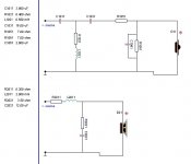
I would agree that the determining factor is the magnitude of the resistance in series with the inductor, if you look at the table of values you will notice they are .2-.3 ohms which is typical of an inductor. This method assumes the person viewing the schematic has the basic knowledge of inductors to draw the conclusion about DCR versus series resistor.
BTW, go easy with definite statements like "you are wrong" especially if you are going to follow it up with "I've seen plenty of..." this is anecdotal evidence and does not mean that the schematics were done properly.
-J
Thanks to those who are knowledgeable in such things.
It is as I suspected......(after closing up the speaker Boxes) DOH!!! the resistor value is in reference to DCR of the Inductor.
I suppose surgery is needed to remove the extra resistance, but other than being padded down in volume they sure sounded great for the $$$ invested.
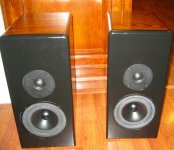
Seas P17RC & Seas 27TFFC in a 19.5 liter cabinet.
Thank you all for your input, and for helping those of us who are not professionally educated in electronics.
I own both of Mr. Jones' tube books but they start at a level above my meager H.S. edumacation.
Thanks guys!
Ron
It is as I suspected......(after closing up the speaker Boxes) DOH!!! the resistor value is in reference to DCR of the Inductor.
I suppose surgery is needed to remove the extra resistance, but other than being padded down in volume they sure sounded great for the $$$ invested.
Seas P17RC & Seas 27TFFC in a 19.5 liter cabinet.
Thank you all for your input, and for helping those of us who are not professionally educated in electronics.
I own both of Mr. Jones' tube books but they start at a level above my meager H.S. edumacation.
Thanks guys!
Ron
Attachments
Have seen a site where the schematics were drawn with the same software as this one, and the poster explained that the resistors were added to simulate the inductor's DCR.
Doesn't matter anyway, they can be assumed to be necessary resistances and the inductor DCR can safely be deducted in any case.
I wouldn't worry about any left over tiny fractions of an ohm")
Doesn't matter anyway, they can be assumed to be necessary resistances and the inductor DCR can safely be deducted in any case.
I wouldn't worry about any left over tiny fractions of an ohm
nunayafb said:IIRC, you are not supposed to put a resistor in the schematic, it is supposed to be spec'd out below the inductance value. However this is just a convention and as long as you put a note on the sheet it is valid.
I would agree that the determining factor is the magnitude of the resistance in series with the inductor, if you look at the table of values you will notice they are .2-.3 ohms which is typical of an inductor. This method assumes the person viewing the schematic has the basic knowledge of inductors to draw the conclusion about DCR versus series resistor.
BTW, go easy with definite statements like "you are wrong" especially if you are going to follow it up with "I've seen plenty of..." this is anecdotal evidence and does not mean that the schematics were done properly.
-J
m0tion said:Sorry to call you out like this, but I think you are wrong.
It's a definitive statement qualified by the fact that it is my opinion, so, I didn't say "you are wrong" I said "I think you are wrong". One of the previous statements is unarguably true ("I think") and the other is possibly true. I don't think I stepped over the line.
Also, anecdotal evidence is perfectly valid in order to determine the meaning of this single instance. The discussion was not regarding proper schematic notation or even schematics in general.
jnb said:
I wouldn't worry about any left over tiny fractions of an ohm
Are you sure? One of my R is .4 Ohms. Seems like it could make a sonic difference when added to the inductor resistance. I'll report back after I remove the R and let ya know if it makes a sonic difference.
Ron
Well to me, tiny is less than 0r4. Right or wrong though, here is an example plot from the Zaphaudio site showing the response differences with a larger DCR difference.
Response plot
EDIT: clarity
Response plot
EDIT: clarity
To me it seems as if the resistors in series with the coil represents the DC resistance of the coil. Their values seem reasonable for coils of those inductances. They are probably drawn in the schematic because that it is the only way to simulate the DCR in this particular simulator.
Has no one as yet mentioned R2021? - this might or might not be a real resistance. The value of 3.5 ohms is far too high to represent the typical esr of even the worst bipolar electrolytic so it is likely to be part of the x-o design..
I usually mark my dcr/esr sim resistors as such and would encourage others to do the same?
I usually mark my dcr/esr sim resistors as such and would encourage others to do the same?
Hmmm.........
R2021 is obviously a real resistor. The others are inductor DCRs but
the point is they do not have to be - they are the values used in the
simulator and could be somewhat pointlessly made up from lower
DCR inductors and real resistors, common sense indicates that they
are ballpark inductor DCR values.
There are also cases where the DCR (usually of an air core) is intended
to be high, i.e. the coil "includes" a circuit resistor, some worry that this
is not as linear as a real resistor, the designers choice.
Using R's in a simulator to represent capacitor ESR ? poor idea.
Capacitor ESR is only valid at a particular frequency and generally
speaking if it is significant in a crossover (same for ESL) it is not
a good choice of capacitor type for the circuit position.
/sreten.
R2021 is obviously a real resistor. The others are inductor DCRs but
the point is they do not have to be - they are the values used in the
simulator and could be somewhat pointlessly made up from lower
DCR inductors and real resistors, common sense indicates that they
are ballpark inductor DCR values.
There are also cases where the DCR (usually of an air core) is intended
to be high, i.e. the coil "includes" a circuit resistor, some worry that this
is not as linear as a real resistor, the designers choice.
Using R's in a simulator to represent capacitor ESR ? poor idea.
Capacitor ESR is only valid at a particular frequency and generally
speaking if it is significant in a crossover (same for ESL) it is not
a good choice of capacitor type for the circuit position.
/sreten.KevinKR,
You are correct R2021 @3.5Ohms is too high for a DCR property of a Cap. It is indeed a component in the Xover. I do not think it is a property of the -)l cap, but the other Rs next to inductors are the inductor DCR.
A poor way to lay out a schematic if you ask me. There were no footnotes to explain the mysteriously small resistance(s).
That was my purpose of this thread. I know I am not the only one to see Xovers like this example. Now I know how to read them.
BTW. Speakers are WAAAY better than their size would suggest.
Thanks to all who offered their help and Knowlege here
Ron
- Status
- This old topic is closed. If you want to reopen this topic, contact a moderator using the "Report Post" button.
- Home
- Loudspeakers
- Multi-Way
- Help reading schematic