Hi all
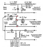
This is the schematic of the crossover of my Spendor SP-1/2E loudspeakers. I’m going to build a new crossover with better parts to compare with the original, maintaining all the same values. I’m sure the sound quality will improve but, if not, I always can reinstall the original and only hardwire the drivers with a better cable.
The capacitors will be ClarityCap SA in L & R matched pairs (a little more expensive than Solen but, according to many opinions, much better sounding). I know that there is a problem when replacing bipolar electrolytics in the mid-treble section with film caps that pass more signal, but, as the original capacitors are already film caps (polyester), I think the ESR of the new polypropylene ones will be very similar, and the HF output will maintain its original balance with the LF.
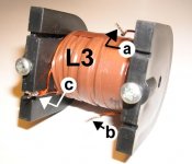
The resistors will be1% non-inductive wirewound Mills MRA-12 and all the four inductors air-cored Solen or Goertz (I don’t know yet) with the same L and DCR values as the originals. I believe Spendor uses an adjustable inductor (L3 in the picture), and not resistors, to set the signal level to the main HF driver and to achieve a L & R pair matching within 1 dB, even if there are slight differences in the responses of each individual Scanspeak D-3806 units. The C2 capacitor value is also modified according the table (however, in my case the value is 1.0 + 0.33= 1.33uF). My doubt is how to measure this L3 adjustable inductor and which air-cored coil or coils to use it its place, so these are my questions:
1) Is the adjustable L3 inductor like having two inductors, the wire between “a” and “c” in series with signal and the wire between “c” and “b” in parallel? (please, see the schematic and the photo attached to this post)
2) If so, I’d have to measure L and DCR between points “a” and “c” and “c” and “b”?
3) To replace L3 is it necessary to use two inductors of these L and DCR values, one in series between C2 and C3 and the other from point “c” to (-) input?
This is the main doubt I have in this upgrading project although, in any case, I could use in it the original standard L3 coil. However, I’d be very grateful if you could help me in sorting this problem.
Thanks in advance
Regards
Jose
This is the schematic of the crossover of my Spendor SP-1/2E loudspeakers. I’m going to build a new crossover with better parts to compare with the original, maintaining all the same values. I’m sure the sound quality will improve but, if not, I always can reinstall the original and only hardwire the drivers with a better cable.
The capacitors will be ClarityCap SA in L & R matched pairs (a little more expensive than Solen but, according to many opinions, much better sounding). I know that there is a problem when replacing bipolar electrolytics in the mid-treble section with film caps that pass more signal, but, as the original capacitors are already film caps (polyester), I think the ESR of the new polypropylene ones will be very similar, and the HF output will maintain its original balance with the LF.
The resistors will be1% non-inductive wirewound Mills MRA-12 and all the four inductors air-cored Solen or Goertz (I don’t know yet) with the same L and DCR values as the originals. I believe Spendor uses an adjustable inductor (L3 in the picture), and not resistors, to set the signal level to the main HF driver and to achieve a L & R pair matching within 1 dB, even if there are slight differences in the responses of each individual Scanspeak D-3806 units. The C2 capacitor value is also modified according the table (however, in my case the value is 1.0 + 0.33= 1.33uF). My doubt is how to measure this L3 adjustable inductor and which air-cored coil or coils to use it its place, so these are my questions:
1) Is the adjustable L3 inductor like having two inductors, the wire between “a” and “c” in series with signal and the wire between “c” and “b” in parallel? (please, see the schematic and the photo attached to this post)
2) If so, I’d have to measure L and DCR between points “a” and “c” and “c” and “b”?
3) To replace L3 is it necessary to use two inductors of these L and DCR values, one in series between C2 and C3 and the other from point “c” to (-) input?
This is the main doubt I have in this upgrading project although, in any case, I could use in it the original standard L3 coil. However, I’d be very grateful if you could help me in sorting this problem.
Thanks in advance
Regards
Jose
Attachments
Hi,
Although I am not familiar with this particular inductor, from what you say here I think that you have got this quite right where your suggested connections are concerned.
I am uncertain quite what is 'adjustable' about the inductor, itself, as those adjustable inductors which I have made for myself have had several different 'taps' on the coils, so that one can vary the inductance of the 2 'legs' of this circuit.
In this case, from what is shown here you are right in that to replicate the effect of this dual arrangement as closely as possible using 2 separate inductors, you should try to match both legs for inductance and DCR. If you can then locate them (in use) with one inductor sitting right next to the other (oriented as this original 'dual' device is now) you should be very close to the original performance here, as moving the 2 inductors apart will have some small effect on their inductances in my experience due to inductive-coupling between the 2 parts.
Good luck with your trials here, and it will be interesting to learn if any changes you do make will substantially affect the final sounds from the speakers. Spendors are well-constructed speakers, anyway, and I wouldn't mind betting that their inductors were probably originally made by Falcon (if they didn't make them, themselves) but either way, I think that they will be quite good quality devices 'as standard'.
I can readily hear sonic differences with different inductors, and for air-coil types, prefer the ribbon constructions over any wire-wound types, including those of Litz consruction (e.g Heptalitz from Solen). However, generally-speaking, I find much more differences and greater potential for sonic improvements with substituting film caps in these x'over circuits, than with inductors.
I hope that this helps.
Regards,
P.S. Thinking a bit more about this, why not try the caps substitution first and keep to the same inductors, to hear what this does, as you can always attend to the inductors later on. Unless these inductors are less well-made than I would guess, this potential for improvements with inductor changes will be very small, and as they cannot be precisely replicated unless they are wound in the same way (possibly with some windings on top of the others) the overall effect will be not be exactly the same. Even when measured separately and exactly matched, their 'dynamic' effect in use will be slightly different due to this mutual inductance not being the same.
Hi again
Thank you for your answer, Bob. My plan is exactly what you have suggested. I have already bought the matched pairs of ClarityCaps and the Mills resistors. The inductors, whatever type I use, are left for a second phase (although perhaps I will not “upgrade” the original coils, as you suggest).
My goal when changing the inductors would be have all of them air-cored, as it seems this is the best inductor when there is no cost- or size-related constraints. You have experience at this, Bob: do you think an air-cored (correctly oriented taking into account its huge magnetic field) is always better than a ferrite-cored of the same L and DCR, or there is no certainty about this or the possible benefits would be minor?
Another option is to change only the two bass series inductors. The series components are the most important of the crossover (all music below 3kHz passes through these coils). I can replace L1 and L2 with air-cored ribbon coils, but only if I found their exact equivalents in both L and DCR (I can measure the actual inductors and not to rely on their stated values) and if they are available in matched pairs. Their interaction (the “dynamic” effect in use you refer to in your answer) is perhaps less important here because it was already reduced between the original two ferrite-cored inductors, as they were placed close but at 90º one to another in the PCB, and the optimum distance and orientation of the new air coils wouldn’t be a problem in a crossover placed in a separate big box.
The problematic tapped inductor (I think this is its correct name) L3 is critical to the very good LF/HF balance of the SP1/2E and perhaps it’s better not to tamper with it. I didn’t know how difficult can be to exactly replicate its behaviour with an arrangement of two air-cored coils, as you have told me. And the inductor L4 is already an air-cored type and it is not in series with the signal, so perhaps upgrade it would be of marginal benefit.
It seems that the less good part in the original crossover are the capacitors and this is where I’m going to start. Moreover, the ClarityCap SA are highly regarded but not too expensive (although they are very big, this is no problem because the crossover will be removed from the interior of the SP1/2E) and it is possible even to tweak the sound through the use of other brands like Mundorf, Hovland, Auricap… in the bypasses, if I want to. This capacitor/resistor improvement, the hardwiring of the crossovers in external boxes (no PCB), and the use of Goertz MI1 cable to connect them directly to the drivers will be probably enough to satisfy me and to enjoy the music through the upgraded SP1/2E“i” ( i for “improved”)")
I’m going to upgrade first only one of the SP1/2E to assess the sonic benefits of the changes, using pink noise and test signals for general balance and several mono recordings heard successively in the original and in the improved loudspeaker for detail and musicality. I’ll post the results when done
Are there more suggestions?
Thanks again
Regards
Jose
Thank you for your answer, Bob. My plan is exactly what you have suggested. I have already bought the matched pairs of ClarityCaps and the Mills resistors. The inductors, whatever type I use, are left for a second phase (although perhaps I will not “upgrade” the original coils, as you suggest).
My goal when changing the inductors would be have all of them air-cored, as it seems this is the best inductor when there is no cost- or size-related constraints. You have experience at this, Bob: do you think an air-cored (correctly oriented taking into account its huge magnetic field) is always better than a ferrite-cored of the same L and DCR, or there is no certainty about this or the possible benefits would be minor?
Another option is to change only the two bass series inductors. The series components are the most important of the crossover (all music below 3kHz passes through these coils). I can replace L1 and L2 with air-cored ribbon coils, but only if I found their exact equivalents in both L and DCR (I can measure the actual inductors and not to rely on their stated values) and if they are available in matched pairs. Their interaction (the “dynamic” effect in use you refer to in your answer) is perhaps less important here because it was already reduced between the original two ferrite-cored inductors, as they were placed close but at 90º one to another in the PCB, and the optimum distance and orientation of the new air coils wouldn’t be a problem in a crossover placed in a separate big box.
The problematic tapped inductor (I think this is its correct name) L3 is critical to the very good LF/HF balance of the SP1/2E and perhaps it’s better not to tamper with it. I didn’t know how difficult can be to exactly replicate its behaviour with an arrangement of two air-cored coils, as you have told me. And the inductor L4 is already an air-cored type and it is not in series with the signal, so perhaps upgrade it would be of marginal benefit.
It seems that the less good part in the original crossover are the capacitors and this is where I’m going to start. Moreover, the ClarityCap SA are highly regarded but not too expensive (although they are very big, this is no problem because the crossover will be removed from the interior of the SP1/2E) and it is possible even to tweak the sound through the use of other brands like Mundorf, Hovland, Auricap… in the bypasses, if I want to. This capacitor/resistor improvement, the hardwiring of the crossovers in external boxes (no PCB), and the use of Goertz MI1 cable to connect them directly to the drivers will be probably enough to satisfy me and to enjoy the music through the upgraded SP1/2E“i” ( i for “improved”)
I’m going to upgrade first only one of the SP1/2E to assess the sonic benefits of the changes, using pink noise and test signals for general balance and several mono recordings heard successively in the original and in the improved loudspeaker for detail and musicality. I’ll post the results when done
Are there more suggestions?
Thanks again
Regards
Jose
Hi Jose,
Taking your points as quickly as possible for now as it is well after midnight, in general I have always preferred air-core inductors in X'overs, simply because you avoid the *possibility* of any saturation problems. Therefore, to me (and as you suggest, in a 'cost no object' situation) it is 'fail-safe'.
However, there are downsides with higher costs being one, and achieving a similar DCR with a large air-coil inductor replacing a cored type might be hard or even impossible, as the gauge of wire might need to be very thick and unmanageable.
Where orientation of coils goes, to reduce any interaction between 2 separate coils (and the converse applies to increase this interaction, if this is the desire) you need to keep them apart as much as possible, with their axes not being similar. This can be best achieved by setting their axes at 90 degrees to each other, and there are several ways in which this can be done, of course. If it is a circular bobbin style, for example, place one with the flat circular end down on the PCB, and place another with the rounded barrel part down on the board. The object is not to have any coils which 'face' in a similar direction like IIII etc., but better as I _ I, if this make sense, but I think that you are aware of this.
Basically, coils which face in a similar direction act like small aerials and receivers, which will give rise to this 'interaction'.
Believe it or not, on many occasions I have found that shunt (i.e. parallel) components will have just as marked an effect on the sound as series components, although I know that this is not intuitive, and it came as a surprise to me, many years ago. So don't automatically assume that shunt components are any less critical in these circuits, as many (most) people do.
Also, capacitors when located close to one another in the same orientation will give rise to cross-talk as I have measured this (this doesn't matter if they are in parallel to achieve a higher value for a single location, though), so keep them apart or orientate them similarly to inductors, if they are in different arms of the circuit.
The term "tapped inductor" you used is quite correct here and when developing speaker X'overs, I usually wind my own from magnet wire and every so many turns on the bobbin, I make a small twisted loop in the wire, which sticks out from the diameter of the finished bobbin. Then you can scrape off the insulation on each loop, and you will have a multi-tapped inductor which you can quickly 'adjust' during development trials by trying different 'taps' to increase/decrease the inductance, to see (or rather hear) what it does to the sound.
Again in general, some of the recent 'specialist' caps are much better sonically than was the case a few years ago, and I agree that this is where the most likely improvements are to be found. Greater transparency with an overall 'cleaner/clearer' sound is a usual benefit, and this will enable you hear further into the tiny details in the recording which make it so much more realistic and enjoyable, and the locations of the original performers will normally become better defined, as examples.
However, with any of these changes, do be prepared for a lot of trial and error experiments with varying component values, as this overall 'balance' of the original sound will most likely change a bit, and I guess that Spendor did a rather good job here. You are quite right to work on only one speaker at a time, and use the non-modded one as a yardstick for comparison purposes, or it is possible to 'drift' somewhat with the overall balance of sound without noticing this very readily, especially if it is in small increments at a time.
Sitting the 2 speakers side-by-side together in the middle of the room (to reduce reflections) and listening to mono signals is very helpful here, especially if you can instantly switch between channels for comparisons. Also you should change over the sources (CD player, amp and cables etc.) from L to R from time to time, as no two channels of any system I have ever experienced are *absolutely* identical sonically. This includes my own audio system, where *every component* in both channels of all pieces of my equipment has been painstakingly matched to ridiculously tight levels! I can still hear very minor differences between the 2 channels due to matters which cannot be controlled and matched absolutely.
Removing X'overs from the cabinet is vital to get the best out of these mods as the vibration, otherwise, is a 'sound-killer' which is much greater in degree than most people understand. Simply doing that alone will almost certainly make a very worthwhile improvement, as I have found in every case which amounts to dozens of different designs.
I hope that this is of some help, but as it is now after 1.00 AM, I am off to bed.
Regards,
L3 is a classic autotransformer achieving simultaneous crossover and attenuation functions in the one component.It's a time honoured tradition with the BBC speaker designs dating back to the 60's and one that Spendor and Harbeth often used in their BBC derived models.Some believe it is subjectively superior to conventional inductor/resistor high pass filters.
The autotransformer as such is not adjustable in this circuit- it doesn't have additional tappings.However by selecting the value of the input side capacitor C2 Spendor was able to match the crossover to different D3806 tweeter sensitivities.These were colour coded after measurement(purple,brown etc)and the appropriate value of C2 (1.83-2.53 uF)selected from the chart to achieve close matching at the crossover point.It would be difficult to duplicate this arrangement using conventional inductors. The crossover frequency and attenuation level would most likely end up quite different to the original design intentions.
Hi,
eanee's contribution here is very useful, and he appears to be familiar with Spencer Hughes' designs, which is something I earlier admitted I am not.
It also clarifies why I suggested that this isn't exactly an "adjustable" inductor, but I assumed that this term came from Spendor as it was shown on the schematic. Normally, anything adjustable in this context would be made in the manner I suggested, with multiple taps.
These helpful comments also reinforce my views that you might not end up with a very satisfactory result when replacing this device with separate inductors, mainly for the reasons I referred to before. Depending on just how the windings are arranged on this autoformer (which I am familiar with in audio amplitude/volume controls, but not in speakers) there will be some inevitable 'interaction' between the two parts making up the device, and, knowing Spendor's reputation, this will have been carefully 'exploited' in the whole scheme of things to end up with the desired sonic results.
Every driver I have measured has had slightly different characteristics from its 'twin' and even the most costly Scan-Speak tweeters which are available in 'matched pairs' (I know as I now use these, and have carefully measured them, actually also in anechoic conditions at another highly-respected UK speaker manufacturers) still exibit slight variations between each other. Accordingly, makers like Spendor will attempt to 'even out' or minimise any discrepancies with careful choices of other components, in order to get closer to a well-matched stereo pair of finished speakers.
Simply copying any X'over schematic from 'nominal' component markings is nowhere near good enough for high-end results as many (most?) of the better manufacturers will deliberately select their capacitors often from the extremes of the tolerance of these components, in order to achieve their wishes. So a cap marked up as 4.7uF with a 10% tolerance could be deliberately chosen to be 5.1uF or perhaps 4.2uF, and this happens with better makers, as I know, especially with the often used Alcap non-polar electrolytics (or similar), with such a wide tolerance.
I don't personally like or use electrolytics in X'overs and my chosen caps are tighter tolerance, anyway, but I match them to obsessively tight levels as a matter of course. To give an example of the cap's values in a recent design of mine: 2.817uF & 2.816, 5.015uF & 5.015, 25.76uF & 25.67, and 100.74uF & 100.94. It was not practically possible to better these matches even when choosing between HQ caps I have in stock which I used to buy by the hundred.
I also 'wound off' some outer turns of the ribbon inductors I used in this design, so that they are exactly the same value for each channel.
Anyway, as I said, if you wish to end up with a very good result, and one which will better Spendor's original efforts, do be prepared for a lot of tweaking of values, although I accept that my obsession with these matters is not entirely essential. Also, in view of eanee's revelation here, this would be even less encouraging for me to change this dual inductor (autoformer) until after all other possibilities have been explored. You have begun with a well-designed pair of speakers in the first place, and, although with more recently-available and better-performing components etc., there is a potential for some improvements, you dont want to end up with a poor result. Just replacing the internal wires will almost certainly make a noticeable difference on its on, in my experience, so do tread carefully, and slowly with this.
Regards,
Hi again
Thank you very much, Bob and Eanee, for your helpful comments and sorry about the delay in answering. I’ve searching a little about the new crossover for my Spendors SP1/2E. At the moment only one of them will be modified and the other speaker will be kept unmodded for reference, in order to assess if there is a genuine improvement with the changes (I hope so).
As I’ve said before, the new resistors will be Mills non-inductive wirewound MRA-12 and all the new capacitors will be Clarity Cap SA series (630v polypropylene1% matched pairs) of the exact same values. If in this stage the modification doesn’t improve the original it won’t be worth any further changes, but if the sound is good the final adjustments can be made by using other brands in C2’, C3’, C4 or C5 if necessary. In several websites (Humble Homemade Hifi, Audio Asylum, Diyaudio… ), other diy-ers post their sonic impressions about the sonic signatures of Mundorf Supreme, Jantzen, Auricap, Hovland, etc., and at these small uF values even these expensive types are affordable (well, almost affordable) for some more experimentation.
The problem are the inductors. I’ve already decided, following your suggestion, not to modify L3, the inductor that does the main tweeter filtering to Scanspeak D3806. Also, I’m going to keep the original L4, the air cored inductor in parallel with the second tweeter. The only inductors I’ll modify are L1 and L2 in series with the polypropylene mid-woofer. I’ve measured them and L1 have L=1.43 mH with a DCR=0.3 ohms, and L2 have L=0.66 mH with a DCR=0.2 ohms.
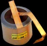
I’ve searched in internet and the Goertz, Solen, Sidewinder or Madisound air cored inductors have all nominal values rather different. For instance, the Goertz foil16AWG 1.5mH has too much DCR (0.394 ohms) but the 14AWG has one too low (0.251 ohms); the Solen 14AWG has 0.41 ohms but the 12AWG has only 0.17 ohms, and so on. Fortunately, I’ve found two brands, with very positive opinions regarding their build and sound quality, that seems to fit better. The Mundorf CFC14 Cu foil aircored 1.50mH has a DCR=0.33 ohms and the 0.68mH has 0.20 ohms, but they are rather expensive. The Jantzen 14AWG Cross Coil foil inductor fits even better and is more affordable, so it is what I’ve decided to use for this crossover modification. Their 1.50mH has a DCR=0.305 ohms and the 0.68mH has 0.196 ohms. However, I’ve some doubts that I’d like to clarify before ordering, and your help will be of great importance here.
a) These Jantzen foil coils have standard inductance values, not the exact same values as the originals, although they are very close (1.43mH and 0.66mH in original filter and 1.50mh and 0.68mH in the new ones). I can measure inductances and by unwinding several foil turns I could replicate the exact original values, and matching the L & R values, but it seems to me that doing this with foil coils is rather difficult. In the photos it seems to be an outer plastic wrap that perhaps holds all the inductor assembly. Have you experience with Jantzen Cross Coils? Can they even be made to order?
b) In case this unwinding is not possible, what is the importance of having coils of 1.5mH and 0.68mh and not 1.43mH and 0.66mH, but whose DCR are almost exactly the same ohmic value as the ferrite-cored ones used by Spendor? I think the series L value sets the frequency where bass filtering takes place and the DCR, in combination with the voice coil resistance, sets the level of this filtering action, so perhaps is easier to unbalance LF and HF in the crossover by changing the DCR than the L value. Remember that I’m not redesigning the original filter (very good and fine-tuned by Spendor), but only trying to hear what does for it a change to more modern and reasonably expensive L, C and R components.
c) Again, if unwinding is not possible, do you believe that the Jantzen nominal +/-3% tolerance is enough for a precise sonic image (Mundorf coils are typically 1.5% tolerance)?
Thanks again for your help
Regards
Jose
Thank you very much, Bob and Eanee, for your helpful comments and sorry about the delay in answering. I’ve searching a little about the new crossover for my Spendors SP1/2E. At the moment only one of them will be modified and the other speaker will be kept unmodded for reference, in order to assess if there is a genuine improvement with the changes (I hope so).
As I’ve said before, the new resistors will be Mills non-inductive wirewound MRA-12 and all the new capacitors will be Clarity Cap SA series (630v polypropylene1% matched pairs) of the exact same values. If in this stage the modification doesn’t improve the original it won’t be worth any further changes, but if the sound is good the final adjustments can be made by using other brands in C2’, C3’, C4 or C5 if necessary. In several websites (Humble Homemade Hifi, Audio Asylum, Diyaudio… ), other diy-ers post their sonic impressions about the sonic signatures of Mundorf Supreme, Jantzen, Auricap, Hovland, etc., and at these small uF values even these expensive types are affordable (well, almost affordable) for some more experimentation.
The problem are the inductors. I’ve already decided, following your suggestion, not to modify L3, the inductor that does the main tweeter filtering to Scanspeak D3806. Also, I’m going to keep the original L4, the air cored inductor in parallel with the second tweeter. The only inductors I’ll modify are L1 and L2 in series with the polypropylene mid-woofer. I’ve measured them and L1 have L=1.43 mH with a DCR=0.3 ohms, and L2 have L=0.66 mH with a DCR=0.2 ohms.
I’ve searched in internet and the Goertz, Solen, Sidewinder or Madisound air cored inductors have all nominal values rather different. For instance, the Goertz foil16AWG 1.5mH has too much DCR (0.394 ohms) but the 14AWG has one too low (0.251 ohms); the Solen 14AWG has 0.41 ohms but the 12AWG has only 0.17 ohms, and so on. Fortunately, I’ve found two brands, with very positive opinions regarding their build and sound quality, that seems to fit better. The Mundorf CFC14 Cu foil aircored 1.50mH has a DCR=0.33 ohms and the 0.68mH has 0.20 ohms, but they are rather expensive. The Jantzen 14AWG Cross Coil foil inductor fits even better and is more affordable, so it is what I’ve decided to use for this crossover modification. Their 1.50mH has a DCR=0.305 ohms and the 0.68mH has 0.196 ohms. However, I’ve some doubts that I’d like to clarify before ordering, and your help will be of great importance here.
a) These Jantzen foil coils have standard inductance values, not the exact same values as the originals, although they are very close (1.43mH and 0.66mH in original filter and 1.50mh and 0.68mH in the new ones). I can measure inductances and by unwinding several foil turns I could replicate the exact original values, and matching the L & R values, but it seems to me that doing this with foil coils is rather difficult. In the photos it seems to be an outer plastic wrap that perhaps holds all the inductor assembly. Have you experience with Jantzen Cross Coils? Can they even be made to order?
b) In case this unwinding is not possible, what is the importance of having coils of 1.5mH and 0.68mh and not 1.43mH and 0.66mH, but whose DCR are almost exactly the same ohmic value as the ferrite-cored ones used by Spendor? I think the series L value sets the frequency where bass filtering takes place and the DCR, in combination with the voice coil resistance, sets the level of this filtering action, so perhaps is easier to unbalance LF and HF in the crossover by changing the DCR than the L value. Remember that I’m not redesigning the original filter (very good and fine-tuned by Spendor), but only trying to hear what does for it a change to more modern and reasonably expensive L, C and R components.
c) Again, if unwinding is not possible, do you believe that the Jantzen nominal +/-3% tolerance is enough for a precise sonic image (Mundorf coils are typically 1.5% tolerance)?
Thanks again for your help
Regards
Jose
Attachments
Hi Jose,
Firstly, I don't have any personal experience of these particular inductors, but I would be surprised if they cannot be wound off to suit your purposes. Why not ask the makers about this, and their method of construction?
My guess is that they are made in a similar manner to those which I am familiar with (Goertz & Alpha-core), and these can be modified without too much difficulty. They are made by winding a long strip of metal foil and polypropylene foil which are initially placed together, with the metal foil being less wide than the plastic, and then wound up until the desired value is achieved. Finally, the flat sides of the made-up coil appear to be heat-treated (or possibly coated with some epoxy varnish) so that the edges of the polypropylene foil are welded together, to give a solid appearance to these faces.
As the plastic strip is wider than the metal this means that there is a band around each side which extends beyond the metal foil which helps to protect the edges of these metal foils. With these extended edges of the plastic being sealed together, that will presumably exclude any air contamination, and make a more solid overall inductor which will be better for vibration resistance.
As for choices made for the inductors and their slightly different parameters, you will need to make this decison yourself, of course, and I wouldn't like to make a guess here which way would be better to try. However, the max difference seems to be less than 5% and many (most?) inductors available probably are not any more accurately made than this level of tolerance, anyway.
Also, bear in mind that you will already be making some changes to the overall 'voicing' of these speakers (whether you like it or not), simply by changing the internal wiring etc, and the many caps/resistors changes, which in my experience will be far more likely to affect the 'voicing' than a 5% difference in one inductor.
Even the fact that your new x'overs will now be external, and of a different physical layout, this will also have some small affect on the sonic results, and you must be prepared for additional experimentation during development, if you wish end up with a neutral sonic result. This, is where the true art of speaker design and the skill of the designer is so important, in my view. I now wonder from some of your comments if you really appreciate just what these proposed changes are likely to do to the overall results, but I am sure that you cannot simply obtain say a more-revealing sound than the originals, without there being some slight changes in some other characteristics
I regret to say that whichever caps you purchase, unless you do what I have done and possibly purchase many (I often buy a hundred or so at one time) and carefully select from those available to you, you will most likely end up with some variation in values of caps, which as I have already advised, is likely to have more sonic effect in my experience, than the inductors do.
Where truly excellent stereo and front/back soundstaging/imaging is concerned, I always attempt to balance both sides as precisely as possible, and the figures I showed before are quite typical for one of my designs. All I can suggest here is that the more care you take and the greater accuracy you can achieve, the better the stereo soundstage will end up, and it is a simple as that. It isn't vital to be obsessive like some of my efforts, but I have never regretted the time and cost I have spent in getting closer to perfection in any such instance.
There is no substitute for practical trials and measurements/listening tests, even if the most careful theoretical decisions have been made, and possibly now you need to carry out some of these trials, to hear what kind of changes result.
This is why I suggest that you should go slowly, and don't spend a lot of money on inductors right away which may, or may not, improve the sonics, and which could give a result which you are not happy with. As you suggest that you are new to this 'experimental' tweaking/improvement work, and as you will be able to readily make some future changes so easily with your new external x'overs, I would take it one step at a time.
Regards,
Hi Jose,
You are welcome, and I hope you find what you are looking for.
These things take some time, and you don't want to spoil anything by rushing the job, or end up compromising anything.
I will be interested to hear about the results when you start installing the new components, but I won't hold my breath waiting for this in the meantime!
Regards,
- Status
- This old topic is closed. If you want to reopen this topic, contact a moderator using the "Report Post" button.
- Home
- Loudspeakers
- Multi-Way
- adjustable inductor in SP1/2E crossover