So i seem to have allot of time on my hands right now and am trying to upgrade my Aperion audio Intimus 532 speakers (actually they are old edge audio speakers but edge changed into aperion). Pretty generic drivers with a Vifa tweeter and 5" woofer.
The crossover that is currently in it has 1 air core inductor, 1 iron core inductor and a resistor (does this seem right? shouldent there be at least one capacitor?). Now i know about crossovers and what not but never actually tried building one from scratch. what would you suggest to get me started on upgrading the current crossover?
Thanks for the help.
Im also in the process of getting the necessary parts to enABL the drivers.
Hi,
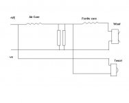
I have drawn out what I think your crossover must be and it is very unusual.
It appears to use the the first inductor as a LF bypass for the tweeter in combination with the resistors.
It also uses the same inductor as a HF block for the woofer incombination with the resistors and a further inductor.
I am at a loss as to why they decided to do it this way but it is interesting none the less.
If you don't have any measurement equipment I wouldn't mess with it it would be very difficult to predice what results you will get.
I would be interested to know if anyone has seen this before or if I have worked it out wrong which is quite possible.
Sorry for the very rough diagram I only had paint available to draw it
Regards,
Andrew
Attachments
An externally hosted image should be here but it was not working when we last tested it.
An externally hosted image should be here but it was not working when we last tested it.
An externally hosted image should be here but it was not working when we last tested it.
An externally hosted image should be here but it was not working when we last tested it.
An externally hosted image should be here but it was not working when we last tested it.
No caps anywhere. I may have access to a multimeter that does measure just about everything, depends on if my friend is willing to share.
The speaker is supposed to have a impedance leveling tech.
From the site:
"HD-X3™ Impedance Leveling Crossover Technology
Aperion's patent-pending HD-X3™ Crossover Technology levels the impedance load across the entire frequency range, creating a remarkably flat frequency response and eliminating the detrimental effects of resistance introduced by long runs of speaker wire. In English, this means that no matter if you have a traditional home theater or your entire house is wired for sound, the performance will always be fantastic without spending a king’s ransom on speaker wire. "
Suggestions/Ideas?
Hi,
Well they are right it will level the impedance, but it is a very brute force way to do it.
Basically the two 15R resistors in parrallel form a 7.5R load in parallel with the woofer and in series with the tweeter.
This means that at low frequencies at least the impedance will never rise above 7.5R but will fall to arround 4R assuming the bass driver is 8 ohms.
The cost for this is that almost 50% of the power going to this speaker is wasted. Hence the need for 2x 25W resistors to be able to dissipate upto 50W.
I doubt this is the best sounding configuration that could be arrived at with these two drive units and you could definately find a more efficient one.
However as I said earlier without measurement equipment the best you can hope for is something that limits the bandwidth to both drive units.
A Xover that would do this could be made with a series 0.5mH inductor on the bass followed by a parallel 33uF cap. For the treble a series 3.3 uF cap followed by a parralel 0.3mH inductor and probably an L pad of 3.3R and say 15R.
This is just some values that will probably be in about the right ball park. They will not intergrate properly and the phase will be messed up. But if you just want something to try this probably won't sound completely broken.
To try to trim this I would adjust the two caps to try to get the midrange balance to sound right the bass 33uF one first and the 3.3R resistor to adjust the treble brightness. (smaller for more treble larger for less) if you feel it is peaking right at the very top then reduce the 15R
I say again, this is not a correct crossover it is just some values that may work, they are typical of the kind of values for these type of drive units.
Regards,
Andrew
I've read articles about the edge/aperion audio's XO circuitry.
As I've understood it, They use some sort of minimalistic series Xo, and uses no capacitor , instead they use a resistor and an inductor to form a high pass filter.
I think you got the schematic drawing wrong. I'm not sure though.
As I've understood it, They use some sort of minimalistic series Xo, and uses no capacitor , instead they use a resistor and an inductor to form a high pass filter.
I think you got the schematic drawing wrong. I'm not sure though.
ccdoggy said:Actually now that i look at the other speaker It says " Licensed by DiAural" on the back.
out of curiosity on a scale of 1-10 what would you make of this crossover. would it be worth replacing?
To my mind the whole DiAural thing is just a way of saying "our XO tech is patented". A properly done series XO (which would be a development on the diaural) would be better IMHO. You would take the air core inductor, toss everything else and put a cap in shunt across the woofer.
http://www.t-linespeakers.org/tech/filters/diaural.html
dave
Dave,
I think one end of the 7.5 ohm resistor is connected to the -ve of the tweeter, not the input?...if so, it's easy to convert it to a 'normal' series xover (with BSC provided by the 2nd L) by replacing the resistor with a cap. Of course, then the tweeter would then need to be padded.
Whether changing the xover would make much difference depends on the drivers' responses outside the xover passband,
do you know what model numbers they are Ccdoggy?
Cheers,
Pete McK
PeteMcK said:I think one end of the 7.5 ohm resistor is connected to the -ve of the tweeter, not the input?
Thanks for the QC,.. i have fixed it.
...if so, it's easy to convert it to a 'normal' series xover (with BSC provided by the 2nd L) by replacing the resistor with a cap. Of course, then the tweeter would then need to be padded.
That would change the low pass to 2nd order from 1st as well... the series iron-core inductor could be shorted to bring it back to 1st order.
It would certainly be simpler with less energy loss in that inductor and in the shunt resistor.
dave
The tweeter is a Vifa D26NC-15-06 and the woofer is a Vifa BC14SG49-08.
T/S specs:
Tweeter:
Size:72mm
VC:26mm
dB:91
W:100
Z:6
Re:4.6
Le:.05
Ce:2.4
Fs:1500
Vas:-
Qms:1.5
Qes:2.3
Qts:.90
Xmax:0.3
Woofer:
Re: 5.55
Le: 0.6
Fs: 53
Qms: 2.73
Qes: 0.53
Qts: 0.45
Mms: 7.8
Vas: 10.5
dB: 86
Vc: 25mm
Bl: 5.2
T/S specs:
Tweeter:
Size:72mm
VC:26mm
dB:91
W:100
Z:6
Re:4.6
Le:.05
Ce:2.4
Fs:1500
Vas:-
Qms:1.5
Qes:2.3
Qts:.90
Xmax:0.3
Woofer:
Re: 5.55
Le: 0.6
Fs: 53
Qms: 2.73
Qes: 0.53
Qts: 0.45
Mms: 7.8
Vas: 10.5
dB: 86
Vc: 25mm
Bl: 5.2
") /sreten.
/sreten.
- Status
- This old topic is closed. If you want to reopen this topic, contact a moderator using the "Report Post" button.
- Home
- Loudspeakers
- Multi-Way
- Replace crossover in existing box