tomcat9 said:
You could try this one out. A good starting point, and maybe good enough to use.
My patience is being severely tried .......
") /sreten.
/sreten."You could try this one out. A good starting point, and maybe good enough to use.
My patience is being severely tried ....... /sreten."
You have tested this and know it doesn't work have you? If so please tell us whats wrong with it. The poster may have spent some time on it.
If you haven't, what is your justification for your comment. You don't have a monopoly on ideas and you may even be wrong.
By the way what did I say that was untrue, be specific. Some of my comments may be value judgements but if they are wrong I would like to know why.
Your comments are often inflamitory and often not very informative. If you don't like discussion on ideas why do you participate in an open forum.
Eg.
"Easier to follow but not as good." - not very informative
"And I'm pretty sure you have no real idea of what you are doing." - inflamitory
My point in my earlier posts was not that the theroretical xover would be better but that it is more important to take control of the design rather than blindly following your or anyone elses crossover. You presented your solution as "just change these resistors till the level is right and it will work" even if this was not your intention that is how it came over. Since you imply you have significant experience with speaker design you must know that this is not the case.
Regards,
Andrew
I'm getting very bored ......
What was not true ? the tweeter is semi-horned loaded at the
frequencies of interest, but its mainly to do with omission.
FWIW a tweeter driven by significant impedance (which it is) with a
Z peak at Fs the response will tend to rise at Fs - an opposite effect
to Fs causing early roll-off, but its not that important in this case.
The frequency area you where discussing is on the edge of the
transition band and stop band of the crossover whilst the main
issue is the transition band either side of the ~ 3Khz c/o point,
the transition band narrowing in bandwidth as the electrical
order of the c/o increases.
As long as the responses are similar in the transition area, the phase
response is by definition similar, so if you assume both tweeters are
flat 2/3 of octave (for 18dB/octave) either side of the 3KHz c/o point
then nothing is going to go hideously wrong. You cannot do this when
the tweeter roll off is part of the transfer function, e.g. 2nd order
electrical @ 2KHz but actually 4th order acoustic e.g. L/R at 1.8kHz.
It was my intention and it is true, especially compared to the other options.
It will not be optimally ideal, but that is a long way from being wrong.
No. Accurate if you can read between the lines of the rest of the
"I am pretty sure im going to go with a Butterworth 2nd order at
3,000hz." post and the assumption he has a sense of humour.
TBH its these sorts of threads that stop the people who do know
their stuff from helping relative newbies, and whilst occasionally
being cantankerous at least I still try.
As for the latest crossover suggestion - you work out how good it is.
/Sreten.
What was not true ? the tweeter is semi-horned loaded at the
frequencies of interest, but its mainly to do with omission.
FWIW a tweeter driven by significant impedance (which it is) with a
Z peak at Fs the response will tend to rise at Fs - an opposite effect
to Fs causing early roll-off, but its not that important in this case.
The frequency area you where discussing is on the edge of the
transition band and stop band of the crossover whilst the main
issue is the transition band either side of the ~ 3Khz c/o point,
the transition band narrowing in bandwidth as the electrical
order of the c/o increases.
As long as the responses are similar in the transition area, the phase
response is by definition similar, so if you assume both tweeters are
flat 2/3 of octave (for 18dB/octave) either side of the 3KHz c/o point
then nothing is going to go hideously wrong. You cannot do this when
the tweeter roll off is part of the transfer function, e.g. 2nd order
electrical @ 2KHz but actually 4th order acoustic e.g. L/R at 1.8kHz.
You presented your solution as "just change these resistors till the level is right
and it will work" even if this was not your intention that is how it came over.
It was my intention and it is true, especially compared to the other options.
It will not be optimally ideal, but that is a long way from being wrong.
"And I'm pretty sure you have no real idea of what you are doing." - inflamitory
No. Accurate if you can read between the lines of the rest of the
"I am pretty sure im going to go with a Butterworth 2nd order at
3,000hz." post and the assumption he has a sense of humour.
TBH its these sorts of threads that stop the people who do know
their stuff from helping relative newbies, and whilst occasionally
being cantankerous at least I still try.
As for the latest crossover suggestion - you work out how good it is.
/Sreten.
I remember a local fellow who proudly presented his speakers
He had tossed something together, a 3way with a cheap premade xo, most of it from scapping other cheap speakers
Enthusiasticly I tried to tell him that it HAD to be measured and so on, but he didnt care much
Surprisingly it played, not the best of all, but probably just as good as all the other stuff like CervinVega and such
Point is that no matter what you do, sound will come from the speakers
I also remember in my youth asking an expert to design me an xo
I wanted a plain standard 6db/18db, but he said nono, he could do better
I did thought his xo looked VERY strange...but he was an expert, and boy, did THAT one sound strange, VERY strange
Morale..Stick to "standard" configured xo like LR 12db, and it will work, not the very top of HiEnd or even good, but probably listenable
Most of modern pop is so poor quality and not worth too much effort
Thank you for your description.
My understanding is that the semi horn loading increases sensitivity at the top end of the response and controls dispersion. Is this not the case.
I was talking about the published response which is driven directly and all we have to make a comparison, but fair point.
Thank you for describing why you belive it will work. I now see that you are right there will probably be minimal variation. I guess the parts I have tried when substituting tweeters must have been working close to the acoustic response because they went badly wrong, hence my concern.
My issue is that as tinitus has said there are so many people who claim there solution is going to work 100% and turn out to be mislead, that without a good description of your rational why should somone take your advice over someone elses.
Regards,
Andrew
Rest assured that Sretens know all the theories of the "high lords" of speaker building ... but I am not sure that there is much real time practise to back it up ... sorry Sreten, I dont hope you are handicapped or anything like it...please dont get offended, but I have never seen any of your work, allthough you should be able to do a decent speaker...so why dont you 
Hi,
Circumstances (where I live) prevail against cabinet DIY and TBH the UK is not a great place for speaker DIY, bit of a rip-off, it is good for second-hand stuff though and the speakers I have are very good.
Recent "real time practise" as you call it is minimal, but in my younger
years I've been there, had the T-shirt and made some of the mistakes,
as well as debunking for myself quite a few hi-fi myths, and this is
fundamentally part of the hobby, understanding whats going on.
I wouldn't argue with this though I do not see it exactly the same way.
It has no effect on nominal sensitivity as the wavelengths are too long.
Its how you understand it / discount it / apply it that counts .........
/sreten.
Circumstances (where I live) prevail against cabinet DIY and TBH the UK is not a great place for speaker DIY, bit of a rip-off, it is good for second-hand stuff though and the speakers I have are very good.
Recent "real time practise" as you call it is minimal, but in my younger
years I've been there, had the T-shirt and made some of the mistakes,
as well as debunking for myself quite a few hi-fi myths, and this is
fundamentally part of the hobby, understanding whats going on.
My understanding is that the semi horn loading increases sensitivity
at the top end of the response and controls dispersion.
Is this not the case.
I wouldn't argue with this though I do not see it exactly the same way.
It has no effect on nominal sensitivity as the wavelengths are too long.
Rest assured that Sreten knows all the theories of the "high lords" of speaker building ...
Its how you understand it / discount it / apply it that counts .........
/sreten.Hi,
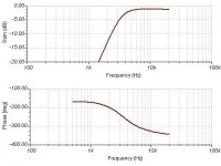
I found I had one of those vifa tweeters sitting in an old cabinet so I have taken measurements of response on axis at 1m and impedance from it.
If someone has one of the vifa bass drivers and can take some measurements then I'll stitch the two together with a simulator and see how it works.
It won't be perfect as the cabinet diffraction will not be right but it should be enough to know how well the xover is going to work.
Regards,
Andrew
Hi,
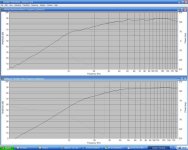
Well it was a wet Sunday afternoon so I decided to try to work out the response of the two different tweeters. The responses are compaired below. If nothing else this has been an interesting exercise for me as I have never used any of these tools before.
In the end I entered both drive units using the data sheets so that the comparision was fair, rather than using measured from one and data sheet from another.
The data was traced in using FRD trace tool then the phase information was extracted using the FRD frequency response combiner program.
After this both sets of data were imported into speaker works and the Swifty crossover network applied to both of them.
Unfortunately the data link given for the Vifa woofer no longer works so I couldn't add the bass drive information to get a full response.
However I think this data is clear enough, whilst there will be some minor deviation arround the crossover region due to slight phase mismatch, overall this is a very good substitution.
I didn't change the values of the resistors in the crossover at all and it appears that this is probably the best option as the SPL is well matched.
Appolagies are in order; Sreten's idea was a very good one.
If anyone has a copy of the vifa data sheet or knows where it can be down loaded I will complete the responses.
Regards,
Andrew
Attachments
gfiandy said:
Unfortunately the data link given for the Vifa woofer no longer works
so I couldn't add the bass drive information to get a full response.
I didn't change the values of the resistors in the crossover at all and it
appears that this is probably the best option as the SPL is well matched.
If anyone has a copy of the vifa data sheet or knows where
it can be down loaded I will complete the responses.
Regards,
Andrew
http://www.tymphany.com/files/products/pdf/BC14SG49-08.pdf
Hi,
Does speakerworks require you to include the .zma file (impedance)
as well as the frd (and phase derived from the frd) ? I played around
a bit with the c/o and "C-16uF" can be increased without affecting
the response much but changing the phase mainly below 2KHz.
Note of course that baffle diffraction will also need simming.
I understand that setting driver offsets is somewhat tricky in sims,
and of course this will affect the relative phase responses / the
reverse null result on a particular axis.
Discussed here :
http://www.geocities.com/woove99/Spkrbldg/DesigningXO.htm
I haven't checked but "3R" with "50R" -> 15R or 22R should be fine.
/sreten.Tympahny must have been updating their web site over the weekend as I couldn't get the data at all. Thanks for the link as I probably would have given up.
Speaker Works uses both .FRD and .ZMA files.
You can set the drive unit offset in the simulation file.
I will have a go at stitching the two together when I get some time. What I plan to do is adjust the offset untill the phase is correct with the Peerless response and it looks like the published data then see what we get when I put the Vifa in. Then I can adjust the crossover for the vifa with a reasonable chance of the real system working that way. Does this seem like a sensible approach? I am a little concerned as both the simulated tweeter responses are showing a much higher SPL than the data on the Swifty.
Regards,
Andrew
Hi,
I'd put in a sensible estimate for offset and see how they match up.
I cannot see a good argument for the Swifty being exactly correct.
Common sense indicates something is awry with the modelled tweeter
output levels, with 1R and 3R in series should be around - 6dB of spec.
/sreten.
I'd put in a sensible estimate for offset and see how they match up.
I cannot see a good argument for the Swifty being exactly correct.
Common sense indicates something is awry with the modelled tweeter
output levels, with 1R and 3R in series should be around - 6dB of spec.
/sreten.Hi,
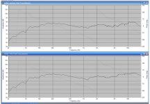
I have entered the Vifa Bass data now that it is available again.
The two responses are shown for the speaker with the Vifa and Peerless tweeters. The bass drivers were ofset by 1inch which seemed to give about the right response.
The both show HF levels about 3dB higher than the Swifty data. This may be microphone error. It may be that the actual tweeter used in the measured system was less sensitive or possibly some thing has gone wrong with the simulation.
The dip arround 1-2KHz can probably be acounted for by baffle diffraction which I did not simulate. Or it may be a difference between the manufactuers data and the unit used for the Swifty design.
However the inportant thing is the tracking between the two different responses, they are very similar. These two plots are taken with the unmodified crossover. Changing to50R to 22R reduces the HF by about 1dB.
I have to say that I have found this quite an interesting exercise and for my next design I will try a simulated from the data sheets exercise before I buy drive units and take real measurements and listen to the speaker.
In the end there seems to be something in the sound quality that snaps into place when something is right. I am not sure yet that any simulation can give you the information what that something is but its a good starting point.
Regards,
Andrew
Attachments
Hi,
The apparent rise of ~ 5dB from 2KHz to 5Khz region to the top octave
is a little perplexing, if this is due to the tweeter inductance then the
reduction of "50R" to "15R" will reduce this significantly.
Its also true a sim does not tell you everything, but they do stop
you stumbling around in the dark hoping to find the lightswitch.
/sreten.
The apparent rise of ~ 5dB from 2KHz to 5Khz region to the top octave
is a little perplexing, if this is due to the tweeter inductance then the
reduction of "50R" to "15R" will reduce this significantly.
Its also true a sim does not tell you everything, but they do stop
you stumbling around in the dark hoping to find the lightswitch.
/sreten.- Status
- This old topic is closed. If you want to reopen this topic, contact a moderator using the "Report Post" button.
- Home
- Loudspeakers
- Multi-Way
- Replace crossover in existing box