DougL said:
Lynn,
I would be interested in your thoughts on how to create a less compromised active crossover. I was thinking of something like an Aikido CF using a 6H6, and a Plus and Minus supply. The other option for me would be to modify my DCX2496 by replace the analog sections with transformers.
Maybe we should start a thread?
Doug
John Atwood and Gary Pimm told me what's inside the commercial active crossovers, and I was appalled. These electronics are no better than what you'd find in a Toyota truck radio - as cheap as it gets, usually bottom-of-the-barrel opamps and the absolute cheapest electrolytics as DC-isolating coupling caps at every stage of the circuit.
The Brand "M" tube crossover uses 12AX7's that are barely lit (less than 0.5 milliamp of current), which are grossly nonlinear into the reactive loads of the active crossover elements, as well as the additional reactances in the feedback networks. John A's modification is to throw away the 12AX7's (which can neither handle much current nor drive a low-impedace load) and use different, high-current tubes like the 5687/7119 family. Unfortunately, the pinouts are different, so this is a major hassle on a circuit board, cutting traces and adding jumpers in many different locations.
The worst-sounding opamp of all time, the 741 and its modern derivatives, are also ubiquitous in low-end electronics - in Brand "B" for example. The giveaway is looking up the device and finding a slew rate under 5V/uSec - these should be discarded before they damage any more audio.
The Signetics/Philips 5532/5534 was the hot ticket in 1979 with its 13V/uSec and supposed 600-ohm drive capability, but that was a long time ago, and opamps, unlike tubes, do not improve with age. There are modern ones that are much faster, more linear, and have better drive capability. I'm not a big fan of Class AB electronics at low levels, but that's what you get with opamps. There are various schemes to force them into Class A by adding an external current source, but not all opamps tolerate this well, and Class A operation needs to be confirmed by measurement. Watch out for stability issues if you try to force opamps into Class A, especially into the reactive feedback networks that active crossovers use.
There are fans of MOSFETs out there, but don't forget that MOSFETs have very high gate capacitances (in the 500 to 1000pF range) and this capacitance is extremely nonlinear, posing a difficult challenge for the preceding stage of amplification.
I'm kind of a bug about this, I know, but considering how few decent-sounding line stages there are, the expectation that an active crossover will sound better doesn't seem very realistic. How can a much more complicated circuit, with complex reactive loads, sometimes in feedback networks, sound better than a simple line stage working into resistive loads?
Returning to the Brand "B" digital crossover that is so popular, the opamps are 741 derivatives, and there are many low-quality electrolytic caps in the signal path. Gary Pimm found the crossover degraded the sound of the high-pass path, even though his high-pass system wasn't connected to the crossover's output!
The culprit turned out to be the electrolytic cap on the input, which even though it was merely connected in parallel with the main linestage output, was degrading the sound of the parallel-connected highpass signal path. He ended up disconnecting all of the opamps and electrolytic caps, and using only transformer coupling for the input and output (connected directly to the ADCs and DACs on the main board). This has the potential drawback of adding a fair amount of cable capacitance to the DAC output, something they may not like. (The delta-sigma DACs have internal opamps that are not defeatable, and have very limited current delivery.)
As for the Aikido, I guess it would work - the output stage with its current-source pulldown would probably handle reactive loads satisfactorily. I'd start with something as mundane as a 6SN7 or 5687 and go from there. With standing currents set to 10 mA or more and reasonably high-impedance parts in the active networks, you should be OK. The main thing is to work out the total loads seen by the active stage over the whole audio band - the loads of the feedback network, filter elements of the following stage (if any), and total cable capacitances that the output stage might see. All of these loads have to be summed, since they appear as the final tube's overall load - the net load at HF is of most interest, since this is reactive and creates an elliptical load-line.
I would not tamper with the internal parts of the Aikido circuit - the SRPP distortion is critically dependent on it being isolated from reactive or low-impedance loads. These things have a critical balance condition and the Aikido is carefully designed to isolate the outside world from the SRPP input section. Leave the insides of the Aikido alone! I'd even go a little further and choose SRPP and output sections with identical tube sections, hoping for distortion cancellation due to complementary current flows in input and output sections.
With my strong preference for very simple circuits (as evident in the Amity and Karna amplifiers), I'm out of my depth with phono preamps, tape electronics, and active crossovers. I usually defer to folks like a John Atwood and Gary Pimm, who seem to know how to tame these critters. I figure anyone that can design a good-sounding phono stage (and both of them have) can tackle active crossovers.
This should be really interesting. hope to see a few builds. Recently dealing with active speakers makes me think something is possible.
Most passive components are tested in voltage source mode where the signal source really does not behave like normal power amps. If we measure inductor and capacitor impedance curves under such loads, they vary quite a bit. I think this is the main reason people design using the ideal model, but the result is very different. This could be one reason why passive XO may sound different from active XOs.
The advantage of active XOs is that components react much closer to analysis, but then it gets into certain non-linearities that mostly is not modelled correctly. So evaluation of active components is a major issue, and more complicated as well.
I would think it more difficult to get active XO to sound excellent. The more complicated XO will benefit from active XO.
soongsc said:
I would think it more difficult to get active XO to sound excellent. The more complicated XO will benefit from active XO.
Yes. Getting them to sound good isn't that hard - decent opamps and decent power supplies (high-speed shunt regulation, please) is what it takes. If you're satisfied with mainstream high-end transistor-amp sound you're all set.
Excellence, though, is another matter.
If you're into good DHT triode or absolute top-rank transistor sound, though, things get more difficult. Good DHT (or the best transistor) amplifiers are extremely transparent and let you hear all of the faults of the preceding electronics. The path then gets much narrower and opamps probably won't be good enough at that point.
One option for the serious discrete-transistor designer are cascoded and current-sourced emitter-followers. The current-source keeps the current in the emitter-follower constant, and the cascode keeps the voltage constant. This can have very low distortion with as few as three transistors. The drawback, and it's an annoying one, is the requirement for a large electrolytic at the output to get rid of the DC offset. The low impedance of the cascoded/current-sourced emitter-follower is very low (normally a good thing), but also demands a low-impedance large-value output coupling-cap as well.
You can DC-servo the voltage going into the base of the transistor, but designing reliable and good-sounding DC servos is an art-form unto itself - people can spend years fiddling around with servo circuits, and completely lose sight of the analog circuit they were trying to design in the first place. Not to mention servos are notorious for momentarily going nuts, going into peculiar and hard-to-reproduce latch-up modes, and destroying all of the following stages with full-rail DC at the output.
The most successful circuits are probably going to be Aikido-class tube circuits or discrete-transistor opamps, like the Deane Jensen JE-990. Both excellent-sounding by absolute standards but not simple - a multiway crossover is going to be a serious project, comparable to a top-quality phono preamp or power amplifier.
My motivations for not going to deeply into active crossovers in the "other" thread was to keep things from getting too complicated and out of hand - it's difficult enough to design a high-efficiency OB speaker (the market isn't exactly filled with them), but adding in the complexities of a serious, studio-monitor-quality active crossover is just too much, at least for me.
I'm not a genius at electronic design, there are lots of others who are better in both vacuum-tube and transistor domains. Any and all insights and contributions are welcome.
This one here seems to use only discrete buffers which are decoupling passive RC stages (my guess from some descriptions):
http://www.fmacoustics.com/c_dom_fm_330.html
But then one has to use LC filters if anything else than Gaussian filters have to be implemented (pure RC filters call for feedback if certain Q - values have to be achieved).
Subtractive topologies or certain EQ circuits would also be tricky to do with buffers.
Some further tiny bits of info on the FM acoustics crossover can be found in one of their newsletters:
http://www.fmacoustics.com/pdf/newsl04.pdf
Regards
Charles
If you go for one of the circuits where output DC level is long way from input, I don't think you need a big coupling electrolytic in all branches of the circuit.
Let us assume the impedance of the following stages is say 10K; then a capacitor to transmit say 100Hz (-3dB) is only 0.16uF, which you can easily get in high quality film. For a mid/high crossover, this is no problem at all.
Even if the impedance chosen is lower, values of several uF are cheap enough and fairly compact.
The low frequency paths do need bigger time constants to avoid unwanted poles, but noise is much less audible at these frequencies, so we can get away with scaling the impedances up without the Johnson noise killing us, so we can use film caps throughout without needing large or expensive parts.
Another point: using unity gain buffers, you can get filter Qs of greater than 0.7 - using a Sallen Key configuration. See http://en.wikipedia.org/wiki/Sallen_Key_filter
Basically, you need to use C1>C2. Clearly you don't want to make a very high Q circuit this way, but I would be really worried about any speaker design that called for filter sections with a Q over say 1.5!
As well as the cascoded follower circuits that Lynn suggested, there are some other neat unity gain designs - the diamond buffer and related circuits.
I suspect that some paths may need an op-amp like element. If it is only in a bass or subwoofer path (say doing something like a LT function), I suspect a decent chip op-amp would be a good compromise, provided the bandwidth is already limited first. But there are also lots of good discrete op-amps, if you needed such functionality in one of the higher frequency paths.
A fun subject, for sure.
I can certainly vouch for the fact that pro active crossovers aren't necessarily the best. And they do vary a lot. Swapping out crossovers in a pro rig you know well can have a BIG influence on the sound - even with the same crossover points and slopes.
There are so many ways to do it. Tubes, transistors, opamps, feedback loops, passive between gain stages, inductors or not, etc.
Just to get the ball rolling on active crossovers, I'll present a few schematics for your consideration and amusement.
Let's start with one that is known to sound very, very good. Solid sate, combo of bipolar and jfet. The Kaneda active filter. A true benchmark. Came as 2 or 3 way filter.
Attachments


An ex-commercial design for DIY was from LCAudio:
http://www.lcaudio.com/index.php?page=29
using opamps for low pass and discrete buffers (Sallen-Key) for high pass.
I have tried that a while go in a 2-way setup around 3kHz, but ended up going back to passive - in spite of testing different opamps (AD826, OPA2132, NE5532) and using shunt regulated supply.
It might have been a matter of taste though: it is difficult to compare active vs. passive since it's virtually impossible to get the exact same response for both. Now I am using an active crossover (DIY, opamp-based) for crossing to OB woofers at 108 Hz - I find active crossovers much more unproblematic and better than passive in the lows.
While we are gathering active crossover circuits, Neil Mcbride has some information on the Naim NAXO circuits at http://www.neilmcbride.co.uk/naxocircuits.html
I include these for completeness - I have some issues with the Naim gain module, but they are much loved by some.
I include these for completeness - I have some issues with the Naim gain module, but they are much loved by some.
Hi,
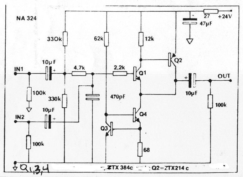
can anyone explain what the four transistors on the right hand side of each of McBride's schematics are doing?
can anyone explain what the four transistors on the right hand side of each of McBride's schematics are doing?
The rightmost pair (ZTX214/ZTX 384) form a complementary darlington for the actual output stage. The two ZTX384s to their left are a strangely drawn "ring of two" current source, acting as a load for the complementary darlington.
Aware of risking to be flamed - I seriously doubt that such crude buffer circuits perform better than modern high-quality op-amps.
Regards
Charles
Regards
Charles
I am not a great fan of the Naim circuits, and merely included them as an example of a discrete design that has seen fairly large scale series production. In particular, the PSRR is very poor - maybe 25dB.
If I ever did another one, for 2 ways, I would just design the low pass, and subrack it from full pass to get the high pass. For three ways, I would design the high and low pass and subtract it from the full pass to get the mid range. Use opamps.
If I ever did another one, for 2 ways, I would just design the low pass, and subrack it from full pass to get the high pass. For three ways, I would design the high and low pass and subtract it from the full pass to get the mid range. Use opamps.
Guess how I cross over and what I use for doing it ??
Regards
Charles
AndrewT said:Hi,
can anyone explain what the four transistors on the right hand side of each of McBride's schematics are doing?
Hi,
One things for certain, he has no idea how to draw a good schematic.
This may help :
Q1 to Q4 are the output arrangement, there appears to be no forward signal path (in the h/p c/o circuit).
🙂/sreten.
Hope it's not acoustic XOsphase_accurate said:
Guess how I cross over and what I use for doing it ??
Regards
Charles
🙂
phase_accurate said:
Guess how I cross over and what I use for doing it ??
Regards
Charles
The problem with this approach is taking driver responses into account correctly.
It produces phase accurate summation for infinite bandwidth drivers - but if you had infinite bandwidth drivers you would not need a crossover.
If you want a phase accurate acoustic response, you then need to put filters in the channels that have the inverse response to the drivers. Now, real drivers fall off at 12db/octave at the low end (faster in in some enclosure types), and typically 18 to 24dB/octave at the high end. This is then kind of hard to make work well.
One things for certain, he has no idea how to draw a good schematic.
Maybe he did it intentionally to cause confusion.
Much the same way as the guy did who draw the schematic that you posted: The "filled plate" of an electrolytic is usually the negative leg !!!!
Regards
Charles
- Status
- Not open for further replies.
- Home
- Loudspeakers
- Multi-Way
- Better-Sounding Active Crossovers