What C1 cap affects ? bigger value will give less/more treble?
Bigger gives more midrange from the Vifa. It won't affect the treble. The bigger the cap, the lower the Vifa plays. It is now set to blend well with the Peerless 12". You should start with 5.7-6.2uF and listen to how it sounds. 6uF will be best for most rooms.
Stands and Legs
It's funny how everyone wants to make a floor stander out of this. I understand, so did I! But it's better with the short baffle up off the floor.
So here's an idea: Why not give it legs?
Since you need to build a 2x2" subframe anyway, you could extend that frame down the the floor. The two 2x2 sticks that run the vertical length behind the baffle, just make them long enough to reach the floor. Those become the front legs.
At the floor run another stick of 2x2 directly backward on the floor from behind each leg. Go back 15-24". Those are the feet. From the back of the feet, run a diagonal stick up to the baffle on each side. Voila! Stand, frame and feet all in one. From the side it would look like a triangle.
The shelf can go at the bottom of the baffle as per normal, or down on the floor. EZ to do, no stand needed and the baffle floats free, as designed. You could even use 2x4" lumber if you wanted the stand to be heavy and solid.
Do I need to draw a picture?
It's funny how everyone wants to make a floor stander out of this. I understand, so did I!
But it's better with the short baffle up off the floor.So here's an idea: Why not give it legs?
Since you need to build a 2x2" subframe anyway, you could extend that frame down the the floor. The two 2x2 sticks that run the vertical length behind the baffle, just make them long enough to reach the floor. Those become the front legs.
At the floor run another stick of 2x2 directly backward on the floor from behind each leg. Go back 15-24". Those are the feet. From the back of the feet, run a diagonal stick up to the baffle on each side. Voila! Stand, frame and feet all in one. From the side it would look like a triangle.
The shelf can go at the bottom of the baffle as per normal, or down on the floor. EZ to do, no stand needed and the baffle floats free, as designed. You could even use 2x4" lumber if you wanted the stand to be heavy and solid.
Do I need to draw a picture?
High Pass cap value
An additional thing to keep in mind is that we have to be careful not to have too much cap as it could extend the low end far enough down toward the Vifa's 110 Hz resonance to cause excursion troubles. Even with the 6 MFD, there is still quite a bit of energy delivered at resonance. Much more capacitance could result in over excursion and driver damage issues. Not to mention an unwanted bump in the frequency response.
An additional thing to keep in mind is that we have to be careful not to have too much cap as it could extend the low end far enough down toward the Vifa's 110 Hz resonance to cause excursion troubles. Even with the 6 MFD, there is still quite a bit of energy delivered at resonance. Much more capacitance could result in over excursion and driver damage issues. Not to mention an unwanted bump in the frequency response.
More crossover thoughts
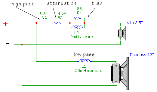
OK, I will be adding a few comments concerning the crossover. Will need to break this up, so just dealing with C1 in this post. The info below assumes a Pad resistor (R2) between 4 and 4.5 ohms.
Using Pano's pretty crossover schematic as a reference, (thanks again Pano) I want to look at the current C1 value and where one may want to experiment.
Keep in mind, the current set up is MY personal preference in My listen room. The main goals were to find a simple layout that provided the best combination of low parts count, tonal balance, power response, musical qualities and long term listen-ability. As with all designs there is room for improvement.
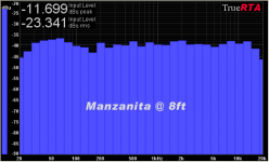
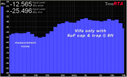
The High pass cap C1 helps to set the low end roll off and partially determines the roll off rate. The best I can measure (combo of RT3 and ARTA) the 6 Mfd provides a 3rd order net acoustic shape with the roll off starting at about 600 Hz and is 18 db down at around 150 Hz. The calculated 1st order electrical predicts a - 3 db at around 1,350 Hz and we should be somewhere around -18 to minus 21 db around 150 Hz. So what is happening is the roll off is delayed by well over an octave, but once it starts it is much steeper than theoretical. What we are seeing is a combination of electrical, baffle (OB F Peak & F = factors) and driver induced roll off forces combining to form a 3rd order acoustic response. So much for depending on electrical only factor(s). I will forward a couple of RT3 files to Pano so he can post them. A picture really demonstrates what is going on.
BTW, the data was taken with the Vifa at 44" off a carpeted floor at a microphone distance of 8'. (On axis) The wall behind the speaker is standard sheet rock and the speaker has about a 10 degree toe in toward the center and is 43 " from baffle face to rear wall. Large room, 21' X 26' X 8' with a lot of furniture and such.
As for playing with the 6 Mfd. To be honest, this value was selected by ear and experience. A smaller room could possibly benefit from a smaller value, say between 5 and 5.8 MFD. But for most I think the 6 Mfd will prove to be the best compromise.
Will talk about the Vifa Pad and trap in the next post.
OK, I will be adding a few comments concerning the crossover. Will need to break this up, so just dealing with C1 in this post. The info below assumes a Pad resistor (R2) between 4 and 4.5 ohms.
Using Pano's pretty crossover schematic as a reference, (thanks again Pano) I want to look at the current C1 value and where one may want to experiment.
Keep in mind, the current set up is MY personal preference in My listen room. The main goals were to find a simple layout that provided the best combination of low parts count, tonal balance, power response, musical qualities and long term listen-ability. As with all designs there is room for improvement.
The High pass cap C1 helps to set the low end roll off and partially determines the roll off rate. The best I can measure (combo of RT3 and ARTA) the 6 Mfd provides a 3rd order net acoustic shape with the roll off starting at about 600 Hz and is 18 db down at around 150 Hz. The calculated 1st order electrical predicts a - 3 db at around 1,350 Hz and we should be somewhere around -18 to minus 21 db around 150 Hz. So what is happening is the roll off is delayed by well over an octave, but once it starts it is much steeper than theoretical. What we are seeing is a combination of electrical, baffle (OB F Peak & F = factors) and driver induced roll off forces combining to form a 3rd order acoustic response. So much for depending on electrical only factor(s). I will forward a couple of RT3 files to Pano so he can post them. A picture really demonstrates what is going on.
BTW, the data was taken with the Vifa at 44" off a carpeted floor at a microphone distance of 8'. (On axis) The wall behind the speaker is standard sheet rock and the speaker has about a 10 degree toe in toward the center and is 43 " from baffle face to rear wall. Large room, 21' X 26' X 8' with a lot of furniture and such.
As for playing with the 6 Mfd. To be honest, this value was selected by ear and experience. A smaller room could possibly benefit from a smaller value, say between 5 and 5.8 MFD. But for most I think the 6 Mfd will prove to be the best compromise.
Will talk about the Vifa Pad and trap in the next post.
Trap inductor
The current design (as in my personal pair) uses a Solen 14 ga. perfect lay which measures about .3 ohm.
Basically if you stay at or below .5 ohm ( 15 ga wire or 16 ga. foil air core) there will be little problem with the trap working as intended. I would avoid iron core inductors for this part of the circuit. Not a lot of price difference and the lower DCR is not needed.
Peerless and Vifa Cut out diameters
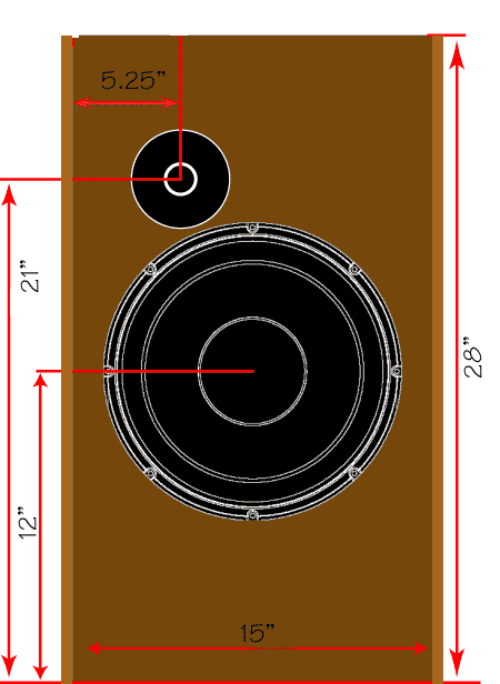
Cut out dimensions can be found at the Madisound or PE web sites. Just for S & G's, the Peerless cut out is 275 MM (10.83" diameter) and the Vifa cut out is 78 MM (3.07"). I add a MM or two on the Peerless and a MM on the Vifa for a touch of wiggle room! Best thing to do of course is once you have the drivers, measure and verify BEFORE you do your cut outs!
Cut out dimensions can be found at the Madisound or PE web sites. Just for S & G's, the Peerless cut out is 275 MM (10.83" diameter) and the Vifa cut out is 78 MM (3.07"). I add a MM or two on the Peerless and a MM on the Vifa for a touch of wiggle room! Best thing to do of course is once you have the drivers, measure and verify BEFORE you do your cut outs!
The current design (as in my personal pair) uses a Solen 14 ga. perfect lay which measures about .3 ohm.
Basically if you stay at or below .5 ohm ( 15 ga wire or 16 ga. foil air core) there will be little problem with the trap working as intended. I would avoid iron core inductors for this part of the circuit. Not a lot of price difference and the lower DCR is not needed.
Very good then. The BOM file for Madisound has a 19 awg shown that is listed at .90 ohm. I'll use the Solens then. Thanks!
What is the recommended height of the stand from the floor? 60 cm from the floor is good?
That makes the stand about 18 to 21" tall.I have found the system to sound the best with the Vifa 38" - 42" off the floor
It is more expensive, but most people like it better for its sound properties. If you are just doing a quick and dirty "let's try this" then MDF of OSB is fine. But if you are going to the expense of paying someone to do the wood work, then the cost difference between MDF and plywood isn't going to be large. Labor will probably be the majority of the cost.
Let's see what John says, but I prefer plywood over MDF, for sure.
Let's see what John says, but I prefer plywood over MDF, for sure.
I've been holding out for that high efficiency version to show up and would like to start collecting parts as funds become available.
It seems like the Seas Prestige FA22RCZ is locked in for the high end and the 18" woofer is still being sorted. I just wanted to see if this is still the case before I order a set.
It seems like the Seas Prestige FA22RCZ is locked in for the high end and the 18" woofer is still being sorted. I just wanted to see if this is still the case before I order a set.
What are the Baltic Birch plywood benefits against the MDF? Is it more expensive?
Better stiffness and better damping to vibrations. A structure of wood with less colouration on the sound. Harder to work it, baltic birch is better and much more expensive.
Baffle material can be MDF or birch ply, or pine ply wood as long as it is at least 0.70" thick and void free. If over 0.875" thick, some slight adjustments in the Vifa rear counter bore may be required. I used birch ply wood due to availability and you have quite a few options as to finishes that can be applied. MDF is not as flexable in terms of finish options.
Concerning the HE version woofer, still auditioning potential woofers. Now awaiting the delivery of a pair of Eminence Sigma 18's with the larger 120 oz magnet. Finding out (AGAIN) that many 18's do not meet advertised specifications, especially efficiency. So far, the Eminence's have been close. MCM, Goodwood and others have fallen between 3 db to as much as 11 db short!! Yikes! What ever I decide on has to be correct for the application AND consistent in meeting specifications. The target is a true measured efficiency of at least 97 dbw and an FS of about 32 Hz or a bit lower. This is taking a lot more time that I thought it would. Anybody need a pile of slightly used 18'S??
Concerning the HE version woofer, still auditioning potential woofers. Now awaiting the delivery of a pair of Eminence Sigma 18's with the larger 120 oz magnet. Finding out (AGAIN) that many 18's do not meet advertised specifications, especially efficiency. So far, the Eminence's have been close. MCM, Goodwood and others have fallen between 3 db to as much as 11 db short!! Yikes! What ever I decide on has to be correct for the application AND consistent in meeting specifications. The target is a true measured efficiency of at least 97 dbw and an FS of about 32 Hz or a bit lower. This is taking a lot more time that I thought it would. Anybody need a pile of slightly used 18'S??
- Home
- Loudspeakers
- Multi-Way
- Fast, fun, Inexpensive OB project