Hello,
since the TH project went really well, i thought about building a unity horn. I tried to design an akabak script to evaluate different variables as horn size, front and rear chamber, front chamber opening into the horn, driver and so on.
My plan is to use the Behringer digital crossover and active amplification to spare me the difficulties of designing a passive crossover. With its small delays for each driver and some carefull measurements, i hope to be able to align the drivers in time.
This is my first attempt at a simulation. If someone is interested, please try it out. I hope to get some feedback about the script. I just implemented all the parts i could identifie by reading alot of threads and looking at pictures of the design, as well as reading the patent.
This script includes just one driver section (in this case the midrange for 300-1000hz), since i dont want to script a compression driver in akabak. An additional woofer section could be implemented as a copy of this script with adjusted variables.
The layout is as follows:
Back enclosure -> Driver -> Front Chamber (duct) -> 2 Ports (duct) -> Horn (waveguide->waveguide->radiator)
(the ports, which connect the front chamber to the horn are connected between both waveguides)
The script: (copy paste into an empty akabak script, press F5 and OK.)
System 'Unity_Segment'
Def_Driver '6ND410'
SD=143cm2 dD1=5cm tD1=2.5cm |Cone
fs=120Hz Mms=8.2g Qms=2.2
Qes=0.27 Re=5.9ohm Le=0.67mH ExpoLe=0.618
Def_Const | Unit is cm
{
Fc_Len=2e-2; | Front chamber length
Fc_dD=14e-2; | Front chamber diameter
FcPort_Len=0.6e-2; | Port length
FcPort_dD=1e-2; | Port diameter
Hi = 2.54e-2; | Horn throat diameter
Mid = 8e-2; | Horn width & height where the ports are
Mouth = 100e-2; | Horn mouth width & height
Hi_Len = 8e-2; | Length of the hornsegment between compression driver and midrange ports
Mid_Len = 100e-2; | Length of the hornsegment between midrange ports and the end of the horn
}
Enclosure 'E1' Node=100 Vb=10L Lb=0
Enclosure 'E2' Node=101 Vb=10L Lb=0
Enclosure 'E3' Node=102 Vb=10L Lb=0
Enclosure 'E4' Node=103 Vb=10L Lb=0
Driver 'D1' Def='6ND410' Node=2=0=100=120
Driver 'D2' Def='6ND410' Node=2=0=101=121
Driver 'D3' Def='6ND410' Node=2=0=102=122
Driver 'D4' Def='6ND410' Node=2=0=103=123
Duct 'Du_Fc1' Node=120=130 dD={Fc_dD} Len={Fc_Len}
Duct 'Du_Fc2' Node=121=131 dD={Fc_dD} Len={Fc_Len}
Duct 'Du_Fc3' Node=122=132 dD={Fc_dD} Len={Fc_Len}
Duct 'Du_Fc4' Node=123=133 dD={Fc_dD} Len={Fc_Len}
Duct 'Du_BP1a' Node=130=150 dD={FcPort_dD} Len={FcPort_Len}
Duct 'Du_BP2a' Node=131=150 dD={FcPort_dD} Len={FcPort_Len}
Duct 'Du_BP3a' Node=132=150 dD={FcPort_dD} Len={FcPort_Len}
Duct 'Du_BP4a' Node=133=150 dD={FcPort_dD} Len={FcPort_Len}
Duct 'Du_BP1b' Node=130=150 dD={FcPort_dD} Len={FcPort_Len}
Duct 'Du_BP2b' Node=131=150 dD={FcPort_dD} Len={FcPort_Len}
Duct 'Du_BP3b' Node=132=150 dD={FcPort_dD} Len={FcPort_Len}
Duct 'Du_BP4b' Node=133=150 dD={FcPort_dD} Len={FcPort_Len}
Waveguide 'W1' Node=140=150 wTh={Hi} hTh={Hi} wMo={Mid} hMo={Mid} Len={Hi_Len} Conical
Waveguide 'W2' Node=150=160 wTh={Mid} hTh={Mid} wMo={Mouth} hMo={Mouth} Len={Mid_Len} Conical
Radiator 'Rad1' Def='W2' Node=160 x=0 y=0 z=0 HAngle=0 VAngle=0
Dear MaVo,
this is an extremely timely post. I have built my implementation of Unity, but the measurements I have taken do not seem to agree with the measurements taken on the "real" Unity.
I am wondering, whether akabak could model the "real" unity with some degrees of precision, which would give me the confidence to try to model my implementation.
I have looked at akabak, but it seems rather complicated, do you have any practical experience with it? Would you be willing to help me?
If so, perhaps e-mailing me would be a better means of communication than the forum: mefistofelez _ at _ hotmail _ dot _ com.
Thank you,
M
I edited your script to model the Misco Speakers model JC5RTF-B sealed back mid range driver. It models in an ideal way. The acoustic pressure rises with frequency to compensate for the falling response of the conical horn. Acoustic power is almost completely flat from 225Hz to 1.6KHz. It looks very good. I've e-mailed Misco Speakers, but have not received a reply yet. I hope they are willing to sell to the general public, or at least in small lots.
Here is the edited script:
Def_Driver 'MidDriver' |Misco Speakers Model JC5RTF-B 5" mid
SD=73.9cm2 dD1=5cm tD1=2.5cm |Cone
fs=500Hz Mms=8.2g Qms=6.4
Qes=2.24 Re=6.7ohm Le=0.78mH ExpoLe=0.618
Def_Const | Unit is cm
{
Fc_Len=0.744e-2; | Front chamber length
Fc_dD=9.7e-2; | Front chamber diameter
FcPort_Len=0.635e-2; | Port length
FcPort_dD=1e-2; | Port diameter
Hi = 2.54e-2; | Horn throat diameter
Mid = 9.2027e-2; | Horn width & height where the ports are
Mouth = 46.223e-2; | Horn mouth width & height
Hi_Len = 6.35e-2; | Length of the horn segment between compression driver and midrange ports
Mid_Len = 33.21e-2; | Length of the horn segment between midrange ports and the end of the horn
}
Radiator 'Diaphragm1' Node=100 SD=73.9cm2
Radiator 'Diaphragm2' Node=101 SD=73.9cm2
Radiator 'Diaphragm3' Node=102 SD=73.9cm2
Radiator 'Diaphragm4' Node=103 SD=73.9cm2
Driver 'D1' Def='MidDriver' Node=2=0=100=120
Driver 'D2' Def='MidDriver' Node=2=0=101=121
Driver 'D3' Def='MidDriver' Node=2=0=102=122
Driver 'D4' Def='MidDriver' Node=2=0=103=123
Duct 'Du_Fc1' Node=120=130 dD={Fc_dD} Len={Fc_Len}
Duct 'Du_Fc2' Node=121=131 dD={Fc_dD} Len={Fc_Len}
Duct 'Du_Fc3' Node=122=132 dD={Fc_dD} Len={Fc_Len}
Duct 'Du_Fc4' Node=123=133 dD={Fc_dD} Len={Fc_Len}
Duct 'Du_BP1a' Node=130=150 dD={FcPort_dD} Len={FcPort_Len}
Duct 'Du_BP2a' Node=131=150 dD={FcPort_dD} Len={FcPort_Len}
Duct 'Du_BP3a' Node=132=150 dD={FcPort_dD} Len={FcPort_Len}
Duct 'Du_BP4a' Node=133=150 dD={FcPort_dD} Len={FcPort_Len}
Duct 'Du_BP1b' Node=130=150 dD={FcPort_dD} Len={FcPort_Len}
Duct 'Du_BP2b' Node=131=150 dD={FcPort_dD} Len={FcPort_Len}
Duct 'Du_BP3b' Node=132=150 dD={FcPort_dD} Len={FcPort_Len}
Duct 'Du_BP4b' Node=133=150 dD={FcPort_dD} Len={FcPort_Len}
Waveguide 'W1' Node=140=150 wTh={Hi} hTh={Hi} wMo={Mid} hMo={Mid} Len={Hi_Len} Conical
Waveguide 'W2' Node=150=160 wTh={Mid} hTh={Mid} wMo={Mouth} hMo={Mouth} Len={Mid_Len} Conical
Radiator 'Rad1' Def='W2' Node=160 x=0 y=0 z=0 HAngle=0 VAngle=0
Below is the Acoustic Pressure

And below is the Acoustic Power

Looks pretty good to me.
Rgs, JLH
Here is the edited script:
Def_Driver 'MidDriver' |Misco Speakers Model JC5RTF-B 5" mid
SD=73.9cm2 dD1=5cm tD1=2.5cm |Cone
fs=500Hz Mms=8.2g Qms=6.4
Qes=2.24 Re=6.7ohm Le=0.78mH ExpoLe=0.618
Def_Const | Unit is cm
{
Fc_Len=0.744e-2; | Front chamber length
Fc_dD=9.7e-2; | Front chamber diameter
FcPort_Len=0.635e-2; | Port length
FcPort_dD=1e-2; | Port diameter
Hi = 2.54e-2; | Horn throat diameter
Mid = 9.2027e-2; | Horn width & height where the ports are
Mouth = 46.223e-2; | Horn mouth width & height
Hi_Len = 6.35e-2; | Length of the horn segment between compression driver and midrange ports
Mid_Len = 33.21e-2; | Length of the horn segment between midrange ports and the end of the horn
}
Radiator 'Diaphragm1' Node=100 SD=73.9cm2
Radiator 'Diaphragm2' Node=101 SD=73.9cm2
Radiator 'Diaphragm3' Node=102 SD=73.9cm2
Radiator 'Diaphragm4' Node=103 SD=73.9cm2
Driver 'D1' Def='MidDriver' Node=2=0=100=120
Driver 'D2' Def='MidDriver' Node=2=0=101=121
Driver 'D3' Def='MidDriver' Node=2=0=102=122
Driver 'D4' Def='MidDriver' Node=2=0=103=123
Duct 'Du_Fc1' Node=120=130 dD={Fc_dD} Len={Fc_Len}
Duct 'Du_Fc2' Node=121=131 dD={Fc_dD} Len={Fc_Len}
Duct 'Du_Fc3' Node=122=132 dD={Fc_dD} Len={Fc_Len}
Duct 'Du_Fc4' Node=123=133 dD={Fc_dD} Len={Fc_Len}
Duct 'Du_BP1a' Node=130=150 dD={FcPort_dD} Len={FcPort_Len}
Duct 'Du_BP2a' Node=131=150 dD={FcPort_dD} Len={FcPort_Len}
Duct 'Du_BP3a' Node=132=150 dD={FcPort_dD} Len={FcPort_Len}
Duct 'Du_BP4a' Node=133=150 dD={FcPort_dD} Len={FcPort_Len}
Duct 'Du_BP1b' Node=130=150 dD={FcPort_dD} Len={FcPort_Len}
Duct 'Du_BP2b' Node=131=150 dD={FcPort_dD} Len={FcPort_Len}
Duct 'Du_BP3b' Node=132=150 dD={FcPort_dD} Len={FcPort_Len}
Duct 'Du_BP4b' Node=133=150 dD={FcPort_dD} Len={FcPort_Len}
Waveguide 'W1' Node=140=150 wTh={Hi} hTh={Hi} wMo={Mid} hMo={Mid} Len={Hi_Len} Conical
Waveguide 'W2' Node=150=160 wTh={Mid} hTh={Mid} wMo={Mouth} hMo={Mouth} Len={Mid_Len} Conical
Radiator 'Rad1' Def='W2' Node=160 x=0 y=0 z=0 HAngle=0 VAngle=0
Below is the Acoustic Pressure
And below is the Acoustic Power
Looks pretty good to me.
Rgs, JLH
Here is the script I came up with for the complete Unity horn. It includes the TAD compression driver, 4 of the Misco mids and the Lambda crossover. The pressure and power responses don't look too good, but I don't think this tells the whole story. I hope you guys enjoy playing with this. It was a lot of work and research to compile this script.
Rgs, JLH
Right below is a picture of the components and node numbers. Hopefully you will be able to read it. The node numbers are in Red text.

System 'Unity_Segment'
Def_Driver 'CompDriver' | TAD TD-2001 compression driver
Sd=18.10cm2
Bl=7.20Tm
Cms=1.60E-04m/N
Rms=2.72Ns/m
fs=310.2990Hz |Mmd = 1.60g not recognised by AkAbak, fs calculated and used instead
Le=0.06mH
Re=6.30ohm
ExpoLe=0.618
Def_Driver 'MidDriver' |Misco Speakers Model JC5RTF-B 5" mid
Sd=73.90cm2
Bl=5.90Tm
Cms=2.07E-04m/N
Rms=0.24Ns/m
fs=500.8646Hz |Mmd = 0.14g not recognised by AkAbak, fs calculated and used instead
Le=0.78mH
Re=6.70ohm
ExpoLe=0.618
Def_Const | Unit is cm
{
Fc_Len=0.744e-2; | Front Mid chamber length
Fc_dD=9.7e-2; | Front Mid chamber diameter
FcPort_Len=0.635e-2; | Mid Port length
FcPort_dD=1e-2; | Mid Port diameter
Rg = 3.00; |Amplifier output impedance (ohms)
R1Comp = 25; |TAD Driver Crossover R1 resistance (ohms)
R2Comp = 25; |TAD Driver Crossover R2 resistance (ohms)
R3Comp = 5; |TAD Driver Crossover R3 resistance (ohms)
R4Comp = 3; |TAD Driver Crossover R1 resistance (ohms)
C1Comp = 2.7e-6; |TAD Driver Crossover C1 capacitor (Farads)
C2Comp = 5.7e-6; |TAD Driver Crossover C2 capacitor (Farads)
L1Comp = 1e-3; |TAD Driver Crossover L1 inductor (Henries)
C1Mid = 45e-6; |Mid Driver Crossover C1 capacitor (Farads)
R1Mid = 12; |Mid Driver Crossover R1 resistance (ohms)
R2Mid = 2; |Mid Driver Crossover R2 resistance (ohms)
L1Mid = 0.2e-3; |Mid Driver Crossover L1 inductor (Henries)
S1 = 5.07e-4; |WG1 throat area (sq cm)
S2 = 84.69e-4; |WG1 mouth area and horn segment 2 throat area Mid tap point(sq cm)
S3 = 2136.63e-4; |WG2 mouth area and horn segment 3 throat area (sq cm)
S4 = 3674.66e-4; |WG3 mouth area Mouth Flare(sq cm)
L12 = 6.35e-2; |WG1 axial length Mid tap point(cm)
L23 = 33.21e-2; |WG2 axial length (cm)
L34 = 8.17e-2; |WG3 axial length Mouth Flare(cm)
VrcComp = 0.14e-3; |TAD Rear chamber volume (litres)
LrcComp = 2.70e-2; |TAD Rear chamber average length (cm)
VtcComp = 0.81e-6; |TAD Throat chamber volume (cc)
AtcComp = 18.10e-4; |TAD Throat chamber cross-sectional area (sq cm)
ArcComp = VrcComp / LrcComp; |Conversions for CompDriver
LtcComp = VtcComp / AtcComp;
}
Radiator 'Diaphragm1' Node=100 SD=73.9cm2
Radiator 'Diaphragm2' Node=101 SD=73.9cm2
Radiator 'Diaphragm3' Node=102 SD=73.9cm2
Radiator 'Diaphragm4' Node=103 SD=73.9cm2
Driver 'D1' Def='MidDriver' Node=0=42=100=120 |Note reverse polarity as seen in Lambda X-over
Driver 'D2' Def='MidDriver' Node=0=42=101=121
Driver 'D3' Def='MidDriver' Node=0=42=102=122
Driver 'D4' Def='MidDriver' Node=0=42=103=123
Duct 'Du_Fc1' Node=120=130 dD={Fc_dD} Len={Fc_Len}
Duct 'Du_Fc2' Node=121=131 dD={Fc_dD} Len={Fc_Len}
Duct 'Du_Fc3' Node=122=132 dD={Fc_dD} Len={Fc_Len}
Duct 'Du_Fc4' Node=123=133 dD={Fc_dD} Len={Fc_Len}
Duct 'Du_BP1a' Node=130=150 dD={FcPort_dD} Len={FcPort_Len} |Note a total of two ports
Duct 'Du_BP2a' Node=131=150 dD={FcPort_dD} Len={FcPort_Len} |per mid driver
Duct 'Du_BP3a' Node=132=150 dD={FcPort_dD} Len={FcPort_Len}
Duct 'Du_BP4a' Node=133=150 dD={FcPort_dD} Len={FcPort_Len}
Duct 'Du_BP1b' Node=130=150 dD={FcPort_dD} Len={FcPort_Len}
Duct 'Du_BP2b' Node=131=150 dD={FcPort_dD} Len={FcPort_Len}
Duct 'Du_BP3b' Node=132=150 dD={FcPort_dD} Len={FcPort_Len}
Duct 'Du_BP4b' Node=133=150 dD={FcPort_dD} Len={FcPort_Len}
Driver 'D5' Def='CompDriver' Node=22=0=31=32
Duct 'CompRearChamber' |TAD rear compression chamber
Node=30=31
SD={ArcComp}
Len={LrcComp}
Visc=0
Duct 'CompFrontChamber' |TAD front throat chamber
Node=32=140
SD={AtcComp}
Len={LtcComp}
Visc=0
Resistor 'Amplifier Rg' |Amplifier output impedance
Node=1=2
R={Rg}
Resistor 'R1Comp'
Node=2=20
R={R1Comp}
Resistor 'R2Comp'
Node=20=0
R={R2Comp}
Resistor 'R3Comp'
Node=21=22
R={R3Comp}
Resistor 'R4Comp'
Node=22=0
R={R4Comp}
Capacitor 'C1Comp'
Node=2=20
C={C1Comp}
Capacitor 'C2Comp'
Node=20=21
C={C2Comp}
Coil 'L1Comp'
Node=20=0
L={L1Comp}
Capacitor 'C1Mid'
Node=2=40
C={C1Mid}
Resistor 'R1Mid'
Node=40=41
R={R1Mid}
Resistor 'R2Mid'
Node=42=0
R={R2Mid}
Coil 'L1Mid'
Node=41=42
L={L1Mid}
Waveguide 'WG1'
Node=140=150
STh={S1}
SMo={S2}
Len={L12}
Conical
Waveguide 'WG2'
Node=150=160
STh={S2}
SMo={S3}
Len={L23}
Conical
Waveguide 'WG3'
Node=160=170
STh={S3}
SMo={S4}
Len={L34}
Conical
Radiator 'Horn mouth'
Node=170
SD={S4}
x=0
y=0
z=0
HAngle=0
VAngle=0
Rgs, JLH
Right below is a picture of the components and node numbers. Hopefully you will be able to read it. The node numbers are in Red text.
System 'Unity_Segment'
Def_Driver 'CompDriver' | TAD TD-2001 compression driver
Sd=18.10cm2
Bl=7.20Tm
Cms=1.60E-04m/N
Rms=2.72Ns/m
fs=310.2990Hz |Mmd = 1.60g not recognised by AkAbak, fs calculated and used instead
Le=0.06mH
Re=6.30ohm
ExpoLe=0.618
Def_Driver 'MidDriver' |Misco Speakers Model JC5RTF-B 5" mid
Sd=73.90cm2
Bl=5.90Tm
Cms=2.07E-04m/N
Rms=0.24Ns/m
fs=500.8646Hz |Mmd = 0.14g not recognised by AkAbak, fs calculated and used instead
Le=0.78mH
Re=6.70ohm
ExpoLe=0.618
Def_Const | Unit is cm
{
Fc_Len=0.744e-2; | Front Mid chamber length
Fc_dD=9.7e-2; | Front Mid chamber diameter
FcPort_Len=0.635e-2; | Mid Port length
FcPort_dD=1e-2; | Mid Port diameter
Rg = 3.00; |Amplifier output impedance (ohms)
R1Comp = 25; |TAD Driver Crossover R1 resistance (ohms)
R2Comp = 25; |TAD Driver Crossover R2 resistance (ohms)
R3Comp = 5; |TAD Driver Crossover R3 resistance (ohms)
R4Comp = 3; |TAD Driver Crossover R1 resistance (ohms)
C1Comp = 2.7e-6; |TAD Driver Crossover C1 capacitor (Farads)
C2Comp = 5.7e-6; |TAD Driver Crossover C2 capacitor (Farads)
L1Comp = 1e-3; |TAD Driver Crossover L1 inductor (Henries)
C1Mid = 45e-6; |Mid Driver Crossover C1 capacitor (Farads)
R1Mid = 12; |Mid Driver Crossover R1 resistance (ohms)
R2Mid = 2; |Mid Driver Crossover R2 resistance (ohms)
L1Mid = 0.2e-3; |Mid Driver Crossover L1 inductor (Henries)
S1 = 5.07e-4; |WG1 throat area (sq cm)
S2 = 84.69e-4; |WG1 mouth area and horn segment 2 throat area Mid tap point(sq cm)
S3 = 2136.63e-4; |WG2 mouth area and horn segment 3 throat area (sq cm)
S4 = 3674.66e-4; |WG3 mouth area Mouth Flare(sq cm)
L12 = 6.35e-2; |WG1 axial length Mid tap point(cm)
L23 = 33.21e-2; |WG2 axial length (cm)
L34 = 8.17e-2; |WG3 axial length Mouth Flare(cm)
VrcComp = 0.14e-3; |TAD Rear chamber volume (litres)
LrcComp = 2.70e-2; |TAD Rear chamber average length (cm)
VtcComp = 0.81e-6; |TAD Throat chamber volume (cc)
AtcComp = 18.10e-4; |TAD Throat chamber cross-sectional area (sq cm)
ArcComp = VrcComp / LrcComp; |Conversions for CompDriver
LtcComp = VtcComp / AtcComp;
}
Radiator 'Diaphragm1' Node=100 SD=73.9cm2
Radiator 'Diaphragm2' Node=101 SD=73.9cm2
Radiator 'Diaphragm3' Node=102 SD=73.9cm2
Radiator 'Diaphragm4' Node=103 SD=73.9cm2
Driver 'D1' Def='MidDriver' Node=0=42=100=120 |Note reverse polarity as seen in Lambda X-over
Driver 'D2' Def='MidDriver' Node=0=42=101=121
Driver 'D3' Def='MidDriver' Node=0=42=102=122
Driver 'D4' Def='MidDriver' Node=0=42=103=123
Duct 'Du_Fc1' Node=120=130 dD={Fc_dD} Len={Fc_Len}
Duct 'Du_Fc2' Node=121=131 dD={Fc_dD} Len={Fc_Len}
Duct 'Du_Fc3' Node=122=132 dD={Fc_dD} Len={Fc_Len}
Duct 'Du_Fc4' Node=123=133 dD={Fc_dD} Len={Fc_Len}
Duct 'Du_BP1a' Node=130=150 dD={FcPort_dD} Len={FcPort_Len} |Note a total of two ports
Duct 'Du_BP2a' Node=131=150 dD={FcPort_dD} Len={FcPort_Len} |per mid driver
Duct 'Du_BP3a' Node=132=150 dD={FcPort_dD} Len={FcPort_Len}
Duct 'Du_BP4a' Node=133=150 dD={FcPort_dD} Len={FcPort_Len}
Duct 'Du_BP1b' Node=130=150 dD={FcPort_dD} Len={FcPort_Len}
Duct 'Du_BP2b' Node=131=150 dD={FcPort_dD} Len={FcPort_Len}
Duct 'Du_BP3b' Node=132=150 dD={FcPort_dD} Len={FcPort_Len}
Duct 'Du_BP4b' Node=133=150 dD={FcPort_dD} Len={FcPort_Len}
Driver 'D5' Def='CompDriver' Node=22=0=31=32
Duct 'CompRearChamber' |TAD rear compression chamber
Node=30=31
SD={ArcComp}
Len={LrcComp}
Visc=0
Duct 'CompFrontChamber' |TAD front throat chamber
Node=32=140
SD={AtcComp}
Len={LtcComp}
Visc=0
Resistor 'Amplifier Rg' |Amplifier output impedance
Node=1=2
R={Rg}
Resistor 'R1Comp'
Node=2=20
R={R1Comp}
Resistor 'R2Comp'
Node=20=0
R={R2Comp}
Resistor 'R3Comp'
Node=21=22
R={R3Comp}
Resistor 'R4Comp'
Node=22=0
R={R4Comp}
Capacitor 'C1Comp'
Node=2=20
C={C1Comp}
Capacitor 'C2Comp'
Node=20=21
C={C2Comp}
Coil 'L1Comp'
Node=20=0
L={L1Comp}
Capacitor 'C1Mid'
Node=2=40
C={C1Mid}
Resistor 'R1Mid'
Node=40=41
R={R1Mid}
Resistor 'R2Mid'
Node=42=0
R={R2Mid}
Coil 'L1Mid'
Node=41=42
L={L1Mid}
Waveguide 'WG1'
Node=140=150
STh={S1}
SMo={S2}
Len={L12}
Conical
Waveguide 'WG2'
Node=150=160
STh={S2}
SMo={S3}
Len={L23}
Conical
Waveguide 'WG3'
Node=160=170
STh={S3}
SMo={S4}
Len={L34}
Conical
Radiator 'Horn mouth'
Node=170
SD={S4}
x=0
y=0
z=0
HAngle=0
VAngle=0
I need to say a few things about my script. Since I use tube amplifiers, I put in a provision for accounting for its higher output impedance. The value for Rg can be changed in the script if you use solid state amplifiers. Second, the conical horn areas and lengths are not from the real Unity horn dimensions. I didn't have that information, so I just came up with my own conical horn design. If anyone has the original Unity horn dimensions and areas please share them.
It is very interesting what happens to the impedance seen by the source when you start changing the crossover values. You can change the Unity’s overall impedance quite a bit without messing up the simulated response. If you need a 16 ohm speaker or an 8 ohm speaker, no problem.
Hopefully we can build on this and come up with a reliable DIY version of the Unity horn.
Rgs, JLH
I put together another script to model a smaller mid driver. I did this to see if I could raise the crossover point some. After poking around I'm pretty pleased with the results. The mid driver I chose are the Misco model JN4C 4" mid. They should be very inexpensive. I made some changes to the crossover values to get a smoother acoustic power response, and a better upward tilting acoustic pressure response to compensate for the conical horn's falling response. The result looks pretty good from 100Hz up past 16KHz. Of course all of this is neat, but the real challenge will be building it. I'm not really in the position to be building anything right now. Man...I hate having to work for a living. 
Rgs, JLH
System 'JN4C_Unity_Horn'
Def_Driver 'CompDriver' | TAD TD-2001 compression driver
Sd=18.10cm2
Bl=7.20Tm
Cms=1.60E-04m/N
Rms=2.72Ns/m
fs=310.2990Hz |Mmd = 1.60g not recognised by AkAbak, fs calculated and used instead
Le=0.06mH
Re=6.30ohm
ExpoLe=0.618
Def_Driver 'MidDriver' |Misco Speakers Model JN4C 4" mid
Sd=47.17cm2
Bl=4.3Tm
Cms=1.01E-03m/N
Rms=0.27Ns/m
fs=95Hz |Mmd = 2.59g not recognised by AkAbak, fs calculated and used instead
Le=0.62mH
Re=6.70ohm
ExpoLe=0.618
Def_Const | Unit is cm
{
Fc_Len=0.81e-2; | Front Mid chamber length
Fc_dD=7.75e-2; | Front Mid chamber diameter |Front chamber volume ~38CC
FcPort_Len=0.635e-2; | Mid Port length (cm)
FcPort_dD=1.18e-2; | Mid Port diameter (cm)
Rg = 3.00; |Amplifier output impedance (ohms)
R1Comp = 25; |TAD Driver Crossover R1 resistance (ohms)
R2Comp = 39; |TAD Driver Crossover R2 resistance (ohms)
R3Comp = 3.3; |TAD Driver Crossover R3 resistance (ohms)
R4Comp = 10; |TAD Driver Crossover R1 resistance (ohms)
C1Comp = 5.1e-6; |TAD Driver Crossover C1 capacitor (Farads)
C2Comp = 3.9e-6; |TAD Driver Crossover C2 capacitor (Farads)
L1Comp = 0.8e-3; |TAD Driver Crossover L1 inductor (Henries)
C1Mid = 36e-6; |Mid Driver Crossover C1 capacitor (Farads)
R1Mid = 18; |Mid Driver Crossover R1 resistance (ohms)
R2Mid = 6.8; |Mid Driver Crossover R2 resistance (ohms)
L1Mid = 0.15e-3; |Mid Driver Crossover L1 inductor (Henries)
S1 = 5.07e-4; |WG1 throat area (sq cm)
S2 = 63.98e-4; |WG1 mouth area and horn segment 2 throat area Mid tap point(sq cm)
S3 = 2136.63e-4; |WG2 mouth area and horn segment 3 throat area (sq cm)
S4 = 3674.66e-4; |WG3 mouth area Mouth Flare(sq cm)
L12 = 5.25e-2; |WG1 axial length Mid tap point(cm)
L23 = 34.92e-2; |WG2 axial length (cm)
L34 = 8.17e-2; |WG3 axial length Mouth Flare(cm)
VrcComp = 0.14e-3; |TAD Rear chamber volume (litres)
LrcComp = 2.70e-2; |TAD Rear chamber average length (cm)
VtcComp = 0.81e-6; |TAD Throat chamber volume (cc)
AtcComp = 18.10e-4; |TAD Throat chamber cross-sectional area (sq cm)
ArcComp = VrcComp / LrcComp; |Conversions for CompDriver
LtcComp = VtcComp / AtcComp;
}
Enclosure 'E1' Node=100 Vb=2L Lb=6.35cm
Enclosure 'E2' Node=101 Vb=2L Lb=6.35cm
Enclosure 'E3' Node=102 Vb=2L Lb=6.35cm
Enclosure 'E4' Node=103 Vb=2L Lb=6.35cm
Driver 'D1' Def='MidDriver' Node=0=42=100=120 |Note reverse polarity as seen in Lambda X-over
Driver 'D2' Def='MidDriver' Node=0=42=101=121
Driver 'D3' Def='MidDriver' Node=0=42=102=122
Driver 'D4' Def='MidDriver' Node=0=42=103=123
Duct 'Du_Fc1' Node=120=130 dD={Fc_dD} Len={Fc_Len}
Duct 'Du_Fc2' Node=121=131 dD={Fc_dD} Len={Fc_Len}
Duct 'Du_Fc3' Node=122=132 dD={Fc_dD} Len={Fc_Len}
Duct 'Du_Fc4' Node=123=133 dD={Fc_dD} Len={Fc_Len}
Duct 'Du_BP1a' Node=130=150 dD={FcPort_dD} Len=0.635cm |Note a total of two ports
Duct 'Du_BP2a' Node=131=150 dD={FcPort_dD} Len=0.635cm |per mid driver
Duct 'Du_BP3a' Node=132=150 dD={FcPort_dD} Len=0.635cm
Duct 'Du_BP4a' Node=133=150 dD={FcPort_dD} Len=0.635cm
Duct 'Du_BP1b' Node=130=150 dD={FcPort_dD} Len=0.635cm
Duct 'Du_BP2b' Node=131=150 dD={FcPort_dD} Len=0.635cm
Duct 'Du_BP3b' Node=132=150 dD={FcPort_dD} Len=0.635cm
Duct 'Du_BP4b' Node=133=150 dD={FcPort_dD} Len=0.635cm
Driver 'D5' Def='CompDriver' Node=22=0=31=32
Duct 'CompRearChamber' |TAD rear compression chamber
Node=30=31
SD={ArcComp}
Len={LrcComp}
Visc=0
Duct 'CompFrontChamber' |TAD front throat chamber
Node=32=140
SD={AtcComp}
Len={LtcComp}
Visc=0
Resistor 'Amplifier Rg' |Amplifier output impedance
Node=1=2
R={Rg}
Resistor 'R1Comp'
Node=2=20
R={R1Comp}
Resistor 'R2Comp'
Node=20=0
R={R2Comp}
Resistor 'R3Comp'
Node=21=22
R={R3Comp}
Resistor 'R4Comp'
Node=22=0
R={R4Comp}
Capacitor 'C1Comp'
Node=2=20
C={C1Comp}
Capacitor 'C2Comp'
Node=20=21
C={C2Comp}
Coil 'L1Comp'
Node=20=0
L={L1Comp}
Capacitor 'C1Mid'
Node=2=40
C={C1Mid}
Resistor 'R1Mid'
Node=40=41
R={R1Mid}
Resistor 'R2Mid'
Node=42=0
R={R2Mid}
Coil 'L1Mid'
Node=41=42
L={L1Mid}
Waveguide 'WG1'
Node=140=150
STh={S1}
SMo={S2}
Len={L12}
Conical
Waveguide 'WG2'
Node=150=160
STh={S2}
SMo={S3}
Len={L23}
Conical
Waveguide 'WG3'
Node=160=170
STh={S3}
SMo={S4}
Len={L34}
Conical
Radiator 'Horn mouth'
Node=170
SD={S4}
x=0
y=0
z=0
HAngle=0
VAngle=0
Here is one using the B&C Speakers DE250 compression driver and the MISCO JN4C mids
System 'JN4C_Unity_Horn'
Def_Driver 'CompDriver' | B&C Speakers DE250
Sd=15cm2
Bl=7.5Tm
Cms=2.0E-05m/N
Rms=1.00Ns/m
Fs=1110Hz
Le=0.025mH
Re=6.30ohm
ExpoLe=0.618
Def_Driver 'MidDriver' |Misco Speakers Model JN4C 4" mid
Sd=47.17cm2
Bl=4.3Tm
Cms=1.01E-03m/N
Rms=0.27Ns/m
fs=95Hz |Mmd = 2.59g not recognised by AkAbak, fs calculated and used instead
Le=0.62mH
Re=6.70ohm
ExpoLe=0.618
Def_Const | Unit is cm
{
Fc_Len=0.81e-2; | Front Mid chamber length
Fc_dD=7.75e-2; | Front Mid chamber diameter |Front chamber volume ~38CC
FcPort_Len=0.635e-2; | Mid Port length (cm)
FcPort_dD=1.18e-2; | Mid Port diameter (cm)
Rg = 3.00; |Amplifier output impedance (ohms)
R1Comp = 10; |B&C Speakers DE250 Crossover R1 resistance (ohms)
R2Comp = 33; |B&C Speakers DE250 Crossover R2 resistance (ohms)
R3Comp = 3.3; |B&C Speakers DE250 Crossover R3 resistance (ohms)
R4Comp = 8; |B&C Speakers DE250 Crossover R1 resistance (ohms)
C1Comp = 10e-6; |B&C Speakers DE250 Crossover C1 capacitor (Farads)
C2Comp = 3.3e-6; |B&C Speakers DE250 Crossover C2 capacitor (Farads)
L1Comp = 1.8e-3; |B&C Speakers DE250 Crossover L1 inductor (Henries)
C1Mid = 47e-6; |Mid Driver Crossover C1 capacitor (Farads)
R1Mid = 15; |Mid Driver Crossover R1 resistance (ohms)
R2Mid = 8; |Mid Driver Crossover R2 resistance (ohms)
L1Mid = 0.15e-3; |Mid Driver Crossover L1 inductor (Henries)
S1 = 5.07e-4; |WG1 throat area (sq cm)
S2 = 63.98e-4; |WG1 mouth area and horn segment 2 throat area Mid tap point(sq cm)
S3 = 2136.63e-4; |WG2 mouth area and horn segment 3 throat area (sq cm)
S4 = 3674.66e-4; |WG3 mouth area Mouth Flare(sq cm)
L12 = 5.25e-2; |WG1 axial length Mid tap point(cm)
L23 = 34.92e-2; |WG2 axial length (cm)
L34 = 8.17e-2; |WG3 axial length Mouth Flare(cm)
VrcComp = 0.08e-3; |B&C Speakers DE250 Rear chamber volume (litres)
LrcComp = 1.27e-2; |B&C Speakers DE250 Rear chamber average length (cm)
VtcComp = 0.75e-6; |B&C Speakers DE250 Throat chamber volume (cc)
AtcComp = 15.0e-4; |B&C Speakers DE250 Throat chamber cross-sectional area (sq cm)
ArcComp = VrcComp / LrcComp; |Conversions for CompDriver
LtcComp = VtcComp / AtcComp;
}
Enclosure 'E1' Node=100 Vb=2L Lb=6.35cm
Enclosure 'E2' Node=101 Vb=2L Lb=6.35cm
Enclosure 'E3' Node=102 Vb=2L Lb=6.35cm
Enclosure 'E4' Node=103 Vb=2L Lb=6.35cm
Driver 'D1' Def='MidDriver' Node=0=42=100=120 |Note reverse polarity as seen in Lambda X-over
Driver 'D2' Def='MidDriver' Node=0=42=101=121
Driver 'D3' Def='MidDriver' Node=0=42=102=122
Driver 'D4' Def='MidDriver' Node=0=42=103=123
Duct 'Du_Fc1' Node=120=130 dD={Fc_dD} Len={Fc_Len}
Duct 'Du_Fc2' Node=121=131 dD={Fc_dD} Len={Fc_Len}
Duct 'Du_Fc3' Node=122=132 dD={Fc_dD} Len={Fc_Len}
Duct 'Du_Fc4' Node=123=133 dD={Fc_dD} Len={Fc_Len}
Duct 'Du_BP1a' Node=130=150 dD={FcPort_dD} Len=0.635cm |Note a total of two ports
Duct 'Du_BP2a' Node=131=150 dD={FcPort_dD} Len=0.635cm |per mid driver
Duct 'Du_BP3a' Node=132=150 dD={FcPort_dD} Len=0.635cm
Duct 'Du_BP4a' Node=133=150 dD={FcPort_dD} Len=0.635cm
Duct 'Du_BP1b' Node=130=150 dD={FcPort_dD} Len=0.635cm
Duct 'Du_BP2b' Node=131=150 dD={FcPort_dD} Len=0.635cm
Duct 'Du_BP3b' Node=132=150 dD={FcPort_dD} Len=0.635cm
Duct 'Du_BP4b' Node=133=150 dD={FcPort_dD} Len=0.635cm
Driver 'D5' Def='CompDriver' Node=22=0=31=32
Duct 'CompRearChamber' |B&C Speakers DE250 rear compression chamber
Node=30=31
SD={ArcComp}
Len={LrcComp}
Visc=0
Duct 'CompFrontChamber' |B&C Speakers DE250 front throat chamber
Node=32=140
SD={AtcComp}
Len={LtcComp}
Visc=0
Resistor 'Amplifier Rg' |Amplifier output impedance
Node=1=2
R={Rg}
Resistor 'R1Comp'
Node=2=20
R={R1Comp}
Resistor 'R2Comp'
Node=20=0
R={R2Comp}
Resistor 'R3Comp'
Node=21=22
R={R3Comp}
Resistor 'R4Comp'
Node=22=0
R={R4Comp}
Capacitor 'C1Comp'
Node=2=20
C={C1Comp}
Capacitor 'C2Comp'
Node=20=21
C={C2Comp}
Coil 'L1Comp'
Node=20=0
L={L1Comp}
Capacitor 'C1Mid'
Node=2=40
C={C1Mid}
Resistor 'R1Mid'
Node=40=41
R={R1Mid}
Resistor 'R2Mid'
Node=42=0
R={R2Mid}
Coil 'L1Mid'
Node=41=42
L={L1Mid}
Waveguide 'WG1'
Node=140=150
STh={S1}
SMo={S2}
Len={L12}
Conical
Waveguide 'WG2'
Node=150=160
STh={S2}
SMo={S3}
Len={L23}
Conical
Waveguide 'WG3'
Node=160=170
STh={S3}
SMo={S4}
Len={L34}
Conical
Radiator 'Horn mouth'
Node=170
SD={S4}
x=0
y=0
z=0
HAngle=0
VAngle=0
John,
You left out the interaction of the midrange chambers with the compression driver (I think - I've never used Akabak). I think it would go between WG1 and WG2 in your schematic. This is an important thing to include in my experience if you want to evaluate effects of the midrange geometry on the tweeter's output. It looks like you did put in the horn segment between the mids and tweeter for the midrange drivers though.
You left out the interaction of the midrange chambers with the compression driver (I think - I've never used Akabak). I think it would go between WG1 and WG2 in your schematic. This is an important thing to include in my experience if you want to evaluate effects of the midrange geometry on the tweeter's output. It looks like you did put in the horn segment between the mids and tweeter for the midrange drivers though.
")
Stop the presses and throw out the previous AkAbak scripts I’ve posted with the Misco Speakers model JC5RTF-B sealed back mid. I will go back and rework the script to correct the errors. I’ve been in contact with Dan Digre of Misco Speakers and he has been a great communicator. Dan sent me the LMS print with all the T/S parameters. See the updated and correct T/S parameters below:
Re = 6.8 ohms
Fs = 491.7Hz
Sd = 63.62 cm2
Mmd = 3.08g
Bl = 5.396
Qms = 7.637
Qes = 2.414
Qts = 1.834
Vas = 0.18 L
Cms = 3.132E-05
Rms = 1.36
Le = 0.788mH

In addition, Dan gave me pricing information. Misco requires a $50 USD minimum purchase and accepts AMEX and Visa over the phone. The price is $28.52 each. In orders of 16 or more (per case) the price drops to $21.53 for each piece. Add shipping and handling. I figure anybody could order a case (16 speakers) and split the cost with another person. Each Unity would need 8 mids per pair. More info to come later.
Rgs, JLH
Re = 6.8 ohms
Fs = 491.7Hz
Sd = 63.62 cm2
Mmd = 3.08g
Bl = 5.396
Qms = 7.637
Qes = 2.414
Qts = 1.834
Vas = 0.18 L
Cms = 3.132E-05
Rms = 1.36
Le = 0.788mH
In addition, Dan gave me pricing information. Misco requires a $50 USD minimum purchase and accepts AMEX and Visa over the phone. The price is $28.52 each. In orders of 16 or more (per case) the price drops to $21.53 for each piece. Add shipping and handling. I figure anybody could order a case (16 speakers) and split the cost with another person. Each Unity would need 8 mids per pair. More info to come later.
Rgs, JLH
John Sheerin said:John,
You left out the interaction of the midrange chambers with the compression driver (I think - I've never used Akabak). I think it would go between WG1 and WG2 in your schematic. This is an important thing to include in my experience if you want to evaluate effects of the midrange geometry on the tweeter's output. It looks like you did put in the horn segment between the mids and tweeter for the midrange drivers though.
John,
I know what you are talking about, but don't know how to script it. Then again, when I simulate just the compression driver or the mids by their selves and overlay them, the combined simulation doesn't behave the same. I think AkAbak is already accounting for the effect of the mid port holes in regards to the compression driver. I have no way to prove this, but it sure looks like it to me. I'll try to post some pictures of what I'm talking about soon. If you have anything else to add I would like to hear it.
Rgs, JLH
Well, the more detailed my model gets the worse the results look. I'm now accounting for the compression driver's rear chamber, air gap between the diaphragm and phasing plug, expansion within phasing plug, the machined throat of the compression driver's body. In addition, I'm accounting for the front air chamber between the midrange's cone and the horn. There are also a few other things. The passive crossover is starting to look pretty ridiculous. I did contact a few people on the forum for crossover advice and they were helpful. Hummmm...I'm not sure how much further I want to take this or how much more time to spend. I have a very strong desire to work out a reasonable and repeatable DIY version of the Unity horn with off the shelf parts. I think it would be great for the DIY community. Ever since the demise of Lambda Acoustics there has been a void. I wonder if we could ever convince Tom Danley to design us one last DIY product?
JLH said:Well, the more detailed my model gets the worse the results look. I'm now accounting for the compression driver's rear chamber, air gap between the diaphragm and phasing plug, expansion within phasing plug, the machined throat of the compression driver's body. In addition, I'm accounting for the front air chamber between the midrange's cone and the horn. There are also a few other things. The passive crossover is starting to look pretty ridiculous. I did contact a few people on the forum for crossover advice and they were helpful. Hummmm...I'm not sure how much further I want to take this or how much more time to spend. I have a very strong desire to work out a reasonable and repeatable DIY version of the Unity horn with off the shelf parts. I think it would be great for the DIY community. Ever since the demise of Lambda Acoustics there has been a void. I wonder if we could ever convince Tom Danley to design us one last DIY product?
The DIY market buying this horn is pretty small, trust me on that. I still have some lenses for these. The lenses were a PITA to make. We ended up using a CNC router to make the 4 sides out of 1.5" Baltic birch. First shop making them burned down and second shop that tried couldn't keep them in spec. I still have a bunch of the parts and the custom tools we made to assemble them if anyone is interested.
nickmckinney said:
The DIY market buying this horn is pretty small, trust me on that. I still have some lenses for these. The lenses were a PITA to make. We ended up using a CNC router to make the 4 sides out of 1.5" Baltic birch. First shop making them burned down and second shop that tried couldn't keep them in spec. I still have a bunch of the parts and the custom tools we made to assemble them if anyone is interested.
Nick,
Shoot me an e-mail with the details.
Thanks, JLH
I've been busy with too much work lately, so not much time to play. I'm still weighing my options. Mean while I've been working on a few more models using additional Misco Speakers. The one with the highest efficiency is the KCN5FD. See the LMS plot below:

The required T/S parameters can be seen in the Akabak scrip below:
System 'KCN5FD_Unity'
Def_Driver 'CompDriver' | BMS 4552ND compression driver
Sd=15.52cm2
Bl=6.21Tm
Cms=140E-06m/N
Rms=0.40Ns/m
Fs=850Hz
Le=0.09mH
Re=6.20ohm
ExpoLe=0.618
Def_Driver 'MidDriver' |Misco Speakers Model KCN5FD 5" mid
Sd=63.62cm2
Bl=5.85Tm
Cms=1.28E-03m/N
Rms=0.27Ns/m
fs=101.336Hz
Le=0.42mH
Re=7.2ohm
ExpoLe=0.618
Def_Const | Unit is cm
{
Fc_Len=0.865e-2; | Front Mid chamber length
Fc_dD=9.0e-2; | Front Mid chamber diameter
FcPort_Len=0.635e-2; | Mid Port length
FcPort_dD=1.38e-2; | Mid Port diameter
Rg=3.00; |Amplifier output impedance (ohms)
R1Comp = 15; |BMS 4552ND Crossover R1 Resistor (Ohms)
R2Comp = 18; |BMS 4552ND Crossover R2 Resistor (Ohms)
C1Comp = 6.8e-6; |BMS 4552ND Crossover C1 capacitor (Farads)
C2Comp = 0.47e-6; |BMS 4552ND Crossover C2 capacitor (Farads)
L1Comp = 1.0e-3; |BMS 4552ND Crossover L1 inductor (Henries)
R1Mid = 2.2; |KCN5FD Crossover R1 Resistor (Ohms)
C1Mid = 33e-6; |KCN5FD Crossover C1 capacitor (Farads)
C2Mid = 75e-6; |KCN5FD Crossover C2 capacitor (Farads)
L1Mid = 0.47e-3; |KCN5FD Crossover L1 inductor (Henries)
S1 = 1.552e-4; |WG1 throat area and Comp phase plug(sq cm)
S2 = 5.07e-4; |WG1 mouth area and horn segment 2 throat area(sq cm)
S3 = 99.01e-4; |WG2 mouth area and horn segment 3 throat area Mid tap point(sq cm)
S4 = 1038.48e-4; |WG3 mouth area and horn segment 4 throat area (sq cm)
S5 = 2141.93e-4; |WG4 mouth area and horn segment 5 throat area (sq cm)
L12 = 2.25e-2; |WG2 axial length(cm)
L23 = 7.0e-2; |WG2 axial length(cm)
L34 = 20.25e-2; |WG3 axial length(cm)
L45 = 7.93e-2; |WG3 axial length(cm)
VrcComp = 0.08e-3; |BMS 4552ND Rear chamber volume (litres)
LrcComp = 0.84e-2; |BMS 4552ND Rear chamber average length (cm)
VtcComp = 0.75e-6; |BMS 4552ND Throat chamber volume (cc)
AtcComp = 15.520e-4; |BMS 4552ND Throat chamber cross-sectional area (sq cm)
ArcComp = VrcComp / LrcComp; |Conversions for CompDriver
LtcComp = VtcComp / AtcComp;
}
Enclosure 'E1' Node=100 Vb=1.8L Lb=5cm
Enclosure 'E2' Node=101 Vb=1.8L Lb=5cm
Enclosure 'E3' Node=102 Vb=1.8L Lb=5cm
Driver 'D1' Def='MidDriver' Node=40=41=100=120
Driver 'D2' Def='MidDriver' Node=40=41=101=121
Driver 'D3' Def='MidDriver' Node=40=41=102=122
Duct 'Du_Fc1' Node=120=130 dD={Fc_dD} Len={Fc_Len}
Duct 'Du_Fc2' Node=121=131 dD={Fc_dD} Len={Fc_Len}
Duct 'Du_Fc3' Node=122=132 dD={Fc_dD} Len={Fc_Len}
Duct 'Du_BP1a' Node=130=160 dD={FcPort_dD} Len={FcPort_Len} |Note a total of two
Duct 'Du_BP2a' Node=131=160 dD={FcPort_dD} Len={FcPort_Len} |ports per mid driver
Duct 'Du_BP3a' Node=132=160 dD={FcPort_dD} Len={FcPort_Len}
Duct 'Du_BP1b' Node=130=160 dD={FcPort_dD} Len={FcPort_Len}
Duct 'Du_BP2b' Node=131=160 dD={FcPort_dD} Len={FcPort_Len}
Duct 'Du_BP3b' Node=132=160 dD={FcPort_dD} Len={FcPort_Len}
Driver 'D5' Def='CompDriver' Node=0=11=31=32
Duct 'CompRearChamber' |BMS 4552ND rear compression chamber
Node=30=31
SD={ArcComp}
Len={LrcComp}
Visc=0
Duct 'CompFrontChamber' |BMS 4552ND front throat chamber
Node=32=140
SD={AtcComp}
Len={LtcComp}
Visc=0
Resistor 'Amplifier Rg' |Amplifier output impedance
Node=1=2
R={Rg}
Resistor 'R1Comp'
Node=10=11
R={R1Comp}
Resistor 'R2Comp'
Node=11=0
R={R2Comp}
Capacitor 'C1Comp'
Node=2=10
C={C1Comp}
Capacitor 'C2Comp'
Node=10=11
C={C2Comp}
Coil 'L1Comp'
Node=10=0
L={L1Comp}
Resistor 'R1Mid'
Node=0=41
R={R1Mid}
Capacitor 'C1Mid'
Node=40=41
C={C1Mid}
Capacitor 'C2Mid'
Node=0=41
C={C2Mid}
Coil 'L1Mid'
Node=2=40
L={L1Mid}
Waveguide 'WG1'
Node=140=150
STh={S1}
SMo={S2}
Len={L12}
Conical
Waveguide 'WG2'
Node=150=160
STh={S2}
SMo={S3}
Len={L23}
Conical
Waveguide 'WG3'
Node=160=170
STh={S3}
SMo={S4}
Len={L34}
Conical
Waveguide 'WG4'
Node=170=180
STh={S4}
SMo={S5}
Len={L45}
Conical
Radiator 'Horn mouth'
Node=180
SD={S5}
x=0
y=0
z=0
HAngle=0
VAngle=0
The KCN5FD is interesting in the fact that it uses a dual ceramic / neo combination magnet. This is a very efficient speaker. In my Akabak model you'll notice I'm only using 3 mids. The idea is to turn a round horn and make something more like the Yorkville unity horn. For those that don't have a lathe, you could build a 6 sided conical horn and mount the mids on every other panel. While I don't have any proof, I would think there would be an acoustical advantage to having the mids firing in the horn 120 degrees apart. I would think there would be much less interaction between the mid ports entering the horn. Anyway, the resulting model is +/- 2dB from 130Hz to 16.5KHz. This should allow for a compact 2-way with a small tapped horn covering the lower frequencies. If anyone needs something in the script explained, just ask me.
Rgs, JLH
Below is the Acoustic Power Response of the KCN5FD unity horn. It is +/- 2dB from 130Hz to 16.5KHz.

Below is the Acoustic Response of the KCN5FD unity horn. Notice the 6db/Oct raise between 500Hz and 10KHz so the resulting acoustic power is flat. You have to design it like this to combat the CD nature of the conical horn. Most CD horns have a falling high frequency response of 6dB/Oct. The real world SPL should be about 102dB 1W/1M minus any power compression.

Rgs, JLH
Below is the Acoustic Response of the KCN5FD unity horn. Notice the 6db/Oct raise between 500Hz and 10KHz so the resulting acoustic power is flat. You have to design it like this to combat the CD nature of the conical horn. Most CD horns have a falling high frequency response of 6dB/Oct. The real world SPL should be about 102dB 1W/1M minus any power compression.
Rgs, JLH
Did you ever buy and mids from Misco?
I was able to get fairly amazing response from a set of Tang Band 2" midranges on an OS waveguide.
Here's the measured polar response:
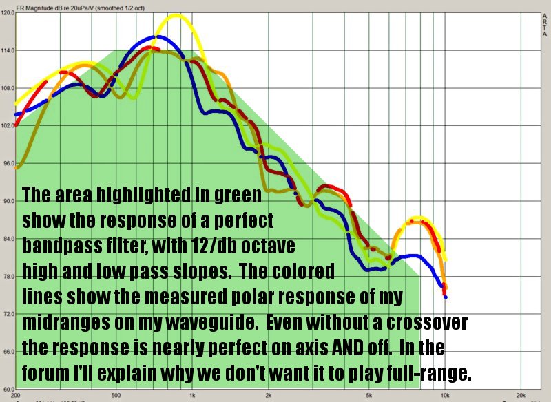
It looks like I have to re-design my waveguide, as the one I built for this project didn't work well. The results above are from an older waveguide, which I built for a project in 2006.
While I work on the new waveguide, I may order some mids from Misco and see how they work.
I emailed them this morning.
I also have another dozen here, including the Galaxy Audio S5N-8, and the Seas L11RCY.
I was able to get fairly amazing response from a set of Tang Band 2" midranges on an OS waveguide.
Here's the measured polar response:
It looks like I have to re-design my waveguide, as the one I built for this project didn't work well. The results above are from an older waveguide, which I built for a project in 2006.
While I work on the new waveguide, I may order some mids from Misco and see how they work.
I emailed them this morning.
I also have another dozen here, including the Galaxy Audio S5N-8, and the Seas L11RCY.
- Status
- This old topic is closed. If you want to reopen this topic, contact a moderator using the "Report Post" button.
- Home
- Loudspeakers
- Multi-Way
- Unity horn script for akabak