Hi,
I'm new to all this but am quite interested in building a t/l 3 way speaker with the Volt RV3143 as the bass driver. I've read some of MJ King's stuff but find it mind bogglingly complicated. I'm only on a Mac computer so I haven't been able to use his worksheets yet unfortunately.
Anyway.... One of the first things that I'm wondering is how do I know what the cross setional area of the line should be? I've read some stuff that gives an equation to work it out and I've read other stuff saying that it should be the same as the Sd of the driver. Can anyone shed any light on this?
I'd also be very interested to hear from anyone who's made a t/l with this driver.
Thanks, and I'm sure that this will be the first of many questions!
jamiematrix said:Anyway.... One of the first things that I'm wondering is how do I know what the cross setional area of the line should be? I've read some stuff that gives an equation to work it out and I've read other stuff saying that it should be the same as the Sd of the driver. Can anyone shed any light on this?
Hi,
You can work out TL cross section and length on paper. I explained it here:
http://www.diyaudio.com/forums/showthread.php?s=&threadid=107889
Quote from the linked thread:
"DrEM,
To make up for my previous blunder I'll try to help out here.
The drivers Fs is 31, use that and the lines taper ratio to get the overall line length.
Using Martin's alignment tables, I get 89 inches with a 3:1 taper for this frequency.
To determine the closed end (So) cross section involves some math. Using the drivers Qts to get variable Dr from table 3: Dr= .1313
Using Fs and taper ratio to get variable Dz from table 2: Dz= 41.73.
Driver Bl is 13.83
Driver Sd is .0363 (m^2)
Driver Re is 6.1
Formula: So/Sd=p*c*Sd*Dz*Dr*Re/(Bl)^2
So/Sd=2.62
So=951 cm^2
That's about 12" x 12" for the cross section line start.
Driver should be somewhere around 1/5 of the way down the line from the start.
The open end will be 317 cm^2. That's about 12" x 4"
Increasing the taper to 4:1 or higher will reduce the line length but could cause vent noise, as the open end gets smaller."
A little math won't kill you!
")
Hi,
Thanks for the reply. In fact I had read your post already -I was just a little confused because I had also read elsewhere that the line area could just be the same as Sd. Is there any truth to that?
From that equation, I've calculated So to be 795 cm2. I believe this driver is used in a PMC MB2 and from the dimensions of their cabinet, either the line area is way smaller (more like Sd) or the line length is way shorter than MJK sugests. Does anybody know much about how they achieved this? Does anybody happen to know what the internal geometry of this speaker is? (Doubtful I know!). The reason that I'm asking is because I'm keen to keep the cabinet as small as possible. With the size that it's looking at the moment, I may look at other possible drivers.
Thaks very much bjorno. So I'm guessing that these are the calculations that I would be able to achieve with MJK's worksheets?
In this arrangement how did you arrive at the cross sectional arrangement -I see that Sl is equal to the driver Sd.
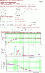
Also, am I right in thinking that the red line in the first chart is the overall theoretical system frequency response?
In this arrangement how did you arrive at the cross sectional arrangement -I see that Sl is equal to the driver Sd.
Also, am I right in thinking that the red line in the first chart is the overall theoretical system frequency response?
DrEM did another sub based on a PMC design a few months ago with good results.
The calculations for line cross section and length give the best size. If this is too big, you can adjust several things, such as taper ratio to get shorter line length. Reduction in cross section is possible without causing too much of a reduction in response.
Typically, the line start should be 2 to 3 x Sd but you can make it smaller.
It's all about compromise. One of the great things about TL geometry is that it is very tolerant of changes (within limits).
Bjorno,
Is there any way that you could run the following parameters through the worksheet? No problem if you don't have the time!!
Line length =2.109 m
Sl = 0.03633 m2
So = 0.07266 m2
Driver position ratio = 0.206
I have used MJK's worksheets to calculate the length and Sl/So although I have reduced Sl/So by about 10% to make the enclosure a little smaller. With John's comments in mind, I guess this shouldn't compromise the design too much.
Thanks a lot for your help.
Also, am I right in thinking that the red line in the first chart is the overall theoretical system frequency response?
Yes!
Is there any way that you could run the following parameters through the worksheet?...
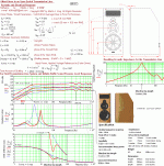
I made reverse engineering of the PMC MB2 speaker too, see the first picture 1(1) and the second picture where your data is compared with my variant.
I guess this shouldn't compromise the design too much.
No and I believe we both our findings are pretty close to the MB2!
b
1(2)
Attachments
Thanks Bjorno that's really very kind of you.
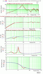
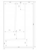
So on paper at least, the bass response looks pretty good right?! I've attached the initial design that I've tried to work out based upon the parameters I was talking about above. This is about as big as I would like the cabinet to be from a practical point of view. I had to lengthen the line just a fraction in order to make enough room on the front baffle for the mid/treble units so it's not exactly the right length -about 5% longer I believe.
I'm looking at using the Wilmslow Audio Prestige driver/crossover kit to build this speaker (Which uses the ATC SM75-150 mid and ScanSpeak R2505/9900 treble). The question for me is... will this give me a better end result than spending the equivalent amount (about 1.8k £GB) on a genuine PMC or similar set of speakers -obviously much smaller!
I suppose this question is impossible to answer until these things are built! Basically though, what I'm looking for is extreme clarity and very low bass extension I'm not too fussed about them being hugely loud though! I don't like the idea of seperate subs as I have always found it awkward to set them up properly and get a good coherent sound. Whenever I have heard any of the large PMC's they sound absolutely incredible and that's what I'm after but I haven't got £6k for a pair of MB1's!
Attachments
...since i am working on a simular one......also i would like to get in contact with Bjorno,if i may.
Hi John,
Tell us about your current project!
b
hi b,thanks for your response,i have a Volt 3143,atc 75/150 non s ,and SS 9700..
cab. is 36 7/8"h,25 7/8"d,15"w.....the front line wall is 9" at the bottom and 8" at top and 21 1/2"h(inside dimension)all 1"mdf.
the rear line wall is 7 1/2"from back and bottom and is straight .
the top exit line is 5"at vent(although the vent was cut 4x12") and the rear vent is 6" and 17 1/2 long..........all inside dimensions. confusing i'm sure but i cant put my pics on only e-mail them,the post won't allow it......i would appreciate any help...my prototype sounds not bad so far but my bottom seems wobbly.
thanks john
John,
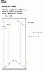
Your description didn’t add up when I tried to make a drawing. You could instead give an instruction, a list of all the cross section areas (CSA: s) and section lengths starting from the closed side of the TL all the way to the open end and point out where the driver is located.
Use MJK: s example as a template: See picture 1(1)
b
1(1)
Attachments
hi b,yes i see now what u mean,it is a 3 chamber with the exit out top front like the PMC MB2, so the 1rst csa is:
9" then behind woofer is 4"(although when i add another 1"front piece for a 2" front will change it to 4 1/2").driver locat is 8 1/2"
next csa is 8" then our first turn 11 1/4, 8, 10 1/4,7 1/2
bottom middle inside turn 6 3/4, 9 1/4, 6 3/4 , 9 1/4, 6 1/2
top turn,6 1/2, 8 7/8 ,6 1/4 and exit is 5"
line lenths are(from closed to open)
24", 8 1/2", 24", 7 1/2", 28", 21 1/2"
csa-9,DL-8 1/2,8,11 1/4,8,10 1/4,7 1/2,6 3/4,9 1/4,6 1/2,6 1/2,
8 7/8,6 1/4,5
i hope this will help B,my anniversary today so gotta go ,thank you very much,
John
hi B,i was shopping with my wife yesterday and bought some memory foam at 3" thick,it is about the perfect thickness for behind woofer. Have you ever tried this product?$$$$$
i am currently using some grey(like roadcase material) 1.5" eggcrate material i purchased from Solen,but was always curious about memory foam..
i just hooked up a Bryston 10b LR x-over at 380 and 3800hz.. the bass is much tighter than the Ashley XR-2001,although the mid is way to high,maybe 2-way,3-way switch is stuck,i will work on this more...
look foreward to hearing back
John
mclsound said:hi B,i was shopping with my wife yesterday and bought some memory foam at 3" thick,it is about the perfect thickness for behind woofer. Have you ever tried this product?$$$$$
i am currently using some grey(like roadcase material) 1.5" eggcrate material i purchased from Solen,but was always curious about memory foam..
i just hooked up a Bryston 10b LR x-over at 380 and 3800hz.. the bass is much tighter than the Ashley XR-2001,although the mid is way to high,maybe 2-way,3-way switch is stuck,i will work on this more...
look foreward to hearing back
John
Memory foam is mostly a closed-cell foam, which means that while it absorbs physical impact, it wil be a poor sound absorber overall. You will, at the least, alter the effective enclosure volume.
-- Mark
- Status
- This old topic is closed. If you want to reopen this topic, contact a moderator using the "Report Post" button.
- Home
- Loudspeakers
- Multi-Way
- Transmission Line Question