Like this??
An externally hosted image should be here but it was not working when we last tested it.
Been thinking about this for my upcoming big speakers. With the lower mids at the top and bottom of a big symmetric array that'll probably end up being about 1.75m tall and only wanting 80-100Hz response there should be enough length. Plan is to build a test box from scrap and see if an opening at the closed end makes some difference. I'll get Martin's software and sim it to get me in the right area.
I used to work for the guy who made Morrison's transmission line enclosures. They were closed end. What is interesting about the design is that instead of one length, the enclosure has 4 different lines, at different lengths. If you looked at the impedance plot, instead of one big hump at the resonant frequency, there would be 4 gradual ones. I never actually saw a tested graph myself, but can tell you the bass was very deep, and very clean.
sardonx said:I used to work for the guy who made Morrison's transmission line enclosures. They were closed end. What is interesting about the design is that instead of one length, the enclosure has 4 different lines, at different lengths. If you looked at the impedance plot, instead of one big hump at the resonant frequency, there would be 4 gradual ones. I never actually saw a tested graph myself, but can tell you the bass was very deep, and very clean.
Morrison inherited that design from Stu Hegeman. The man was a genius. The enclosure can't really be called a TL thou as the lines aren't really long enuff.
dave
No intent to belittle Morrison. Stu hand picked him to carry on his work and from what i understand he has added his own important wotk to the concept. This is a speaker i'd really like to hear someday. I did sell the Hegemans when i worked hifi in the late 70s and they were special... 30 years of steady development can't have hurt ")
dave
dave
Interesting. Any idea on the details of the implementation?sardonx said:I used to work for the guy who made Morrison's transmission line enclosures. They were closed end. What is interesting about the design is that instead of one length, the enclosure has 4 different lines, at different lengths. If you looked at the impedance plot, instead of one big hump at the resonant frequency, there would be 4 gradual ones. I never actually saw a tested graph myself, but can tell you the bass was very deep, and very clean.
I stuck my head inside the earlier hegemans. The box was a square prism ~a foot & 2-3 high (baffle was at an angle with driver firing into a reflector). The bottom of the box was divided up into many square pipes of differing length.
A while back there was an aXp article (12/03) that described something similar but simplier applied to a subwoofer.
dave
A while back there was an aXp article (12/03) that described something similar but simplier applied to a subwoofer.
dave
Thanks Dave. So as I begin to experiment, any suggestions, even WAG as to Sd, So? Or am I starting fron scratch? Sounds like I could have a plenum volume and build the box intenals similar to B&W matrix, but not open all the 'pipes' that form to the adjacent ones, and just block them at varying points. Should be relatively easy to make a test box. Final enclosure will be similar in size and appearance to the Duntech/Dunlavy's. Or at least that's the plan.planet10 said:I stuck my head inside the earlier hegemans. The box was a square prism ~a foot & 2-3 high (baffle was at an angle with driver firing into a reflector). The bottom of the box was divided up into many square pipes of differing length.
A while back there was an aXp article that described something simplier but similar.
dave
I hesitate to suggest how big the pipes were because it was a long time ago and my memory of it is fuzzy. Something like an 8x8 or 12x12 arrary inside the ~12x12 box. The walls of the tubes were quite small, and i'm thinking aluminum or maybe painted cardboard... sorry, 30 years have only left faint details...
dave
dave
Thanks, that still gives me some ideas. Might make a straight rectangular test box, say 40x40 (driver here) and 180cm long with a simple longitudinal matrix and strart experimenting. Worth a sheet of scrap MDF to get it right. I guess an Sl=So TL type idea is as good a place to start as any.planet10 said:I hesitate to suggest how big the pipes were because it was a long time ago and my memory of it is fuzzy. Something like an 8x8 or 12x12 arrary inside the ~12x12 box. The walls of the tubes were quite small, and i'm thinking aluminum or maybe painted cardboard... sorry, 30 years have only left faint details...
dave
Jus' thinkin' out loud.
Cheers
Interesting. Any idea on the details of the implementation?
I don't know the exact details. When i was working there Morrison had already begun making his cheaper non-transmission look-a likes with poly or paper woofers (as you can see on his site) and that's what we made for him.
On the real version, with the woofer out, there was a horizontal plate very close to the magnet which forced the sound to the outer walls where the transmission lines began.
The other thing I know is that tons of epoxy is used in the construction.
good night!
i'm a nweb in the forum, so please forgive me if my question is being silly...
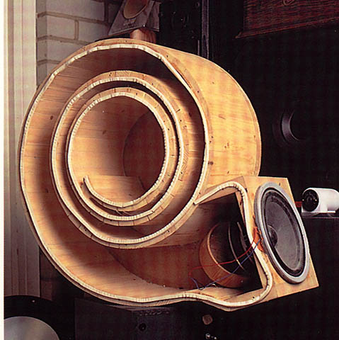
i did some classical transmission line enclosures in the past, all of them "open ended". this time i would like to use a driver with an Fs at about 20Hz (coming to L26 from Seas) and do half wave ressonator like this one. that would give me a tube with almost 7meters lengh, which is impracticable.
i understand the concept of this one, but what i don't understand how to calculate the distance of the tube knowing it will get thinner and thinner... precisely like B&W Nautilus showned up!
can you please give me information about this? or where to search information to do so?
and considering that i would like to hear/feel the 20Hz with high fidelity, is this the ideal approach, or should i stick to the classical TLs?
thank you very much, and once again, please forgive me if i'm being to newb...
i'm a nweb in the forum, so please forgive me if my question is being silly...
i did some classical transmission line enclosures in the past, all of them "open ended". this time i would like to use a driver with an Fs at about 20Hz (coming to L26 from Seas) and do half wave ressonator like this one. that would give me a tube with almost 7meters lengh, which is impracticable.
i understand the concept of this one, but what i don't understand how to calculate the distance of the tube knowing it will get thinner and thinner... precisely like B&W Nautilus showned up!
can you please give me information about this? or where to search information to do so?
and considering that i would like to hear/feel the 20Hz with high fidelity, is this the ideal approach, or should i stick to the classical TLs?
thank you very much, and once again, please forgive me if i'm being to newb...
Morrison inherited that design from Stu Hegeman. The man was a genius. The enclosure can't really be called a TL thou as the lines aren't really long enuff.
dave
OT I know, but I had the pleasure of meeting Stu Hegeman in the early 80s. I also got to take home for audition a Hapi 1 preamp SN 0001.
A concept which has interested me greatly but I haven't managed to do much experimentation with. I should get some small cheap speakers (high fs) and plastic pipes and see how I can influence the impedence plot with different configurations, see how theory and practise come together
Seems as though a closed end TL would be excellent for a woofer assisted fullrange design or a system using an extended bandwidth midrange. I had even considered modifying the Dayton RS-52 with a Nautilus style tapering tube on it's rear, but the advantages are more applicable to passive crossover designs I feel.
Best of luck with your project, I look forward to reading your results
Last edited:
- Status
- This old topic is closed. If you want to reopen this topic, contact a moderator using the "Report Post" button.
- Home
- Loudspeakers
- Multi-Way
- Closed End Transmission Line