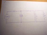
I am messing around with line array using piezo's.I am a little slow on wiring.After reading posts and trying to understand as its easier in drawing form I came up with this.Am I even close?From the cts website I have the values but need help with putting it in layman's terms.I only need 1 per woofer but for asthetics I want 2,to get woofer line and tweeter line close in size.Thanks
Attachments
Cal Weldon said:
Also, the higher the frequency, the harder it is to integrate multiple units. See if you can get away with just one.
Are they horns? No (practical) problem with horns. Why is that Cal ?
PE/Resources/Speaker Building
• Piezoelectric Tweeters (295K PDF)
http://www.partsexpress.com/resources.cfm
What kind of piezo do you have?
• Piezoelectric Tweeters (295K PDF)
http://www.partsexpress.com/resources.cfm
What kind of piezo do you have?
Inductor said:Are they horns? No (practical) problem with horns. Why is that Cal ?
You will sacrifice some vertical dispersion and have to live with the fact that no two tweeters sound identical. Always use the least amount of drivers capable of meeting the requirements. Especially in the higher frequencies.
KISS
")
Inductor said:No (practical) problem with horns... (???)
... Also, the 1/4wavelength distance between them (is) difficult to achieve to prevent cancelation.
There is an experiment by Beyma Spain for a 3-Tweeter horn in a speaker that worked very well, named "WL5 Developement"(pdf).
(here>)
http://profesional.beyma.com/ENGLISH/recursos.php#
Good question shawn. (post#14) When the tweeter has been "shunted" with the 22 ohm resistor as per Dave's schematic the cap now functions as a conventional cross over component and not as an attentuation component. It now "sees" a resistance of 22ohms not the purely capacitive load of the original piezo.
Planet10 gave me a link a couple of posts up.The last paragraph might as well be chinese to me.Could somebody draw that out for me.I am confused on series caps and shunts.I thought shunt was series and series cap was parallel.HELP,I'm so lost.here it is.............Looking from the amp, first the series crossover cap, say 4 uF, then the 22 ohm shunt from hot to ground, then a series cap of about 0.15 uF for 6 dB attenuation, and then a series resistor of about 30-50 ohms to tame the very top end, then the piezo itself.
shawn what you've just described sounds pretty right actually. I've got the original article (JAES) by the Motorola engineer (called Bost? I think) and that's where a lot of this stuff comes from graphs etc. The two caps function differently in the two different positions as previously mentioned. The same goes for the resistor. When the resistor is between the 22ohm resistance and the tweeter it attenuates the higher frequencies. If you put it on the other side of the 22ohm (ie back on the amp side) it would attenuate volume.
Now "series" means the signal passes thru' both components but one after the other, ok? "Shunt" and parrallel are the same (we just do this to confuse people! ha ha). Think of the signal passing thru' both of the components at the same time in parallel. Hope that makes sense. BTW we all had to wrestle with this stuff....you're not alone. If you want to do the theory and enjoy working from first principles then put "electrical impedance" in google and you'll probably get a strqaightforward tute somewhere. But hang in there man, your on the right track!!!
Now "series" means the signal passes thru' both components but one after the other, ok? "Shunt" and parrallel are the same (we just do this to confuse people! ha ha). Think of the signal passing thru' both of the components at the same time in parallel. Hope that makes sense. BTW we all had to wrestle with this stuff....you're not alone. If you want to do the theory and enjoy working from first principles then put "electrical impedance" in google and you'll probably get a strqaightforward tute somewhere. But hang in there man, your on the right track!!!
shawn1972 said:Looking from the amp, first the series crossover cap, say 4 uF, then the 22 ohm shunt from hot to ground.
Xover with a 0.48 cap and a 22R resistor.
Maybe this is what you are looking for.
(Add up ~2 dBs for a second piezo to this xover curve output.)
Attachments
- Status
- This old topic is closed. If you want to reopen this topic, contact a moderator using the "Report Post" button.
- Home
- Loudspeakers
- Multi-Way
- Piezo help