I doubt it. Bose is one of the most maligned manufacturers on this site and I don't believe that anyone will have the schematics or the willingness to aid someone in modifying said manufacturers' equipment. And even though this is a DIY site, the general opinion would be that modifing it will not help, but you could sell it and buy twice as much "better" equipment for the money you obtain.
Simply posting the same question in different forums every 20 minutes is not going to gain you any friends either.
That said, why do you want the schematic?
Simply posting the same question in different forums every 20 minutes is not going to gain you any friends either.
That said, why do you want the schematic?
Hi Cloth Ears,
Sorry if I posted twice, still a little clumsy on posting, it’s the first time to participate in a forum.
Why I need the schematics?
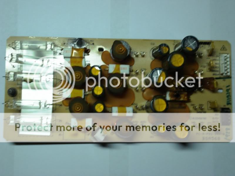
Well the crossover burnt like fireworks. I try to attach some pictures. I need the specification of the burnt parts. Therefore I would truly appreciate if someone could help me out with the schematics or the details of the burnt parts.
A picture in return might do as well.
Thanks again buddies, hope you can help me.
Sorry if I posted twice, still a little clumsy on posting, it’s the first time to participate in a forum.
Why I need the schematics?
Well the crossover burnt like fireworks. I try to attach some pictures. I need the specification of the burnt parts. Therefore I would truly appreciate if someone could help me out with the schematics or the details of the burnt parts.
A picture in return might do as well.
Thanks again buddies, hope you can help me.
It might not just be your crossover. check the output of your amplifier with a DC voltmeter.
Resistors can get incredibly hot and still be good. Burning a bit of glue is no big deal. Those ceramic ones are usually good until they crack, they usually melt themselves off the board first. If that happened to the crossover you should measure the voice coils in your speakers. I don't think they would have survived.
Electrolytic capacitors are not the best for crossovers, neither are ferrite cored inductors, then placing all of said inductors in the same orientation causes a lot if interaction between them.
The only thing I see here that doesn't make me cringe is the circuit board appears to be fibreglass. It's cheaper to do all of this filtering before the amplifier then you can use an amp of half the power instead of wasting it all in this heater board.
Sorry mate, I think this crossover is the healthiest part of your system. If you can measure DC on your amplifier output and the voice coils are open circuit I suggest you finish the job in the back yard by lightly washing the whole system down with diesel then lighting it up. Please post it on Youtube.
You could use any surviving speakers on your PC with a little amp.
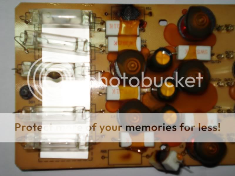
Are those light bulbs on the right?
Resistors can get incredibly hot and still be good. Burning a bit of glue is no big deal. Those ceramic ones are usually good until they crack, they usually melt themselves off the board first. If that happened to the crossover you should measure the voice coils in your speakers. I don't think they would have survived.
Electrolytic capacitors are not the best for crossovers, neither are ferrite cored inductors, then placing all of said inductors in the same orientation causes a lot if interaction between them.
The only thing I see here that doesn't make me cringe is the circuit board appears to be fibreglass. It's cheaper to do all of this filtering before the amplifier then you can use an amp of half the power instead of wasting it all in this heater board.
Sorry mate, I think this crossover is the healthiest part of your system. If you can measure DC on your amplifier output and the voice coils are open circuit I suggest you finish the job in the back yard by lightly washing the whole system down with diesel then lighting it up. Please post it on Youtube.
You could use any surviving speakers on your PC with a little amp.
Are those light bulbs on the right?
Ooohh pretty xover (sarcasm)
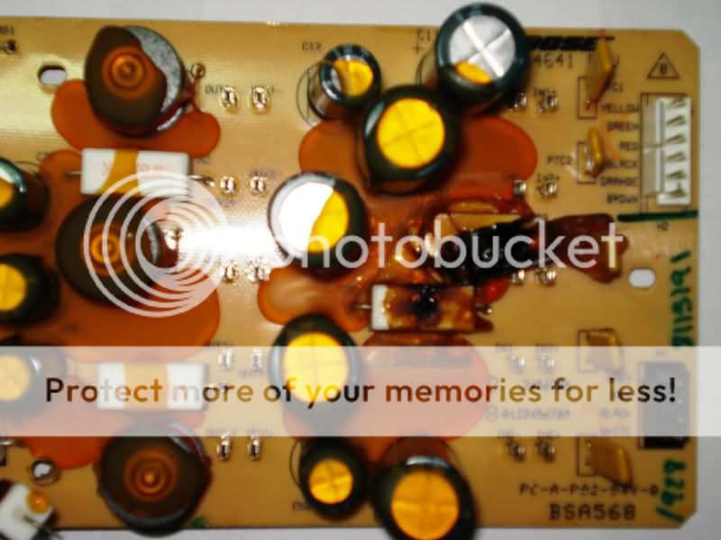
The 'light bulbs' on the left could be overdrive protection, if they are faulty you could replace them with a wire link (just remember that excess volume will then cause driver damage).
The small orange 'chips' on the right look like ptc's (thermistors) also for driver protection. See above coment for repair if faulty.
Why they have used two types of protection is beyond me.
The wire wound resistors are common and cheap.
Might also pay to replace the electrolytic caps, known to leak in all bose equipment due to them using the cheapest parts available.
MadMutt said:
Why they have used two types of protection is beyond me.
I think what happens, is that is when the polyswitches get too hot, they change to nearly infinite resistance. This throws the signal through the bulbs thus allowing the signal to pass, but at a reduced level. (As the bulds filaments get hot, they also increase in resistance)
So the polyswitches and the bulbs act in conjuction, rather than being separate protection devices.
If this is the case, then bypassing the bulbs with wire would negate all the protections, and almost certainly fry the drivers.
Ok, but it's not a valve amp so there should be no need for load protection of that degree.
Not like a transistor amp will go unstable with no load connected.
If the system had two way speakers then maybe the bulb would be for the high pass and the polyswitch for the low pass.
But that would be silly.
Even for a marketing company such as bose that would be silly.
That top bulb looks suss by the way.
Hi Buddies
Thru all my misery into trying to repair my sound system, I somehow start enjoying this forum, anyway that said.
Indeed your right the crossover is most probably the healthiest part of my system.
The main problem is in the back yard, the amplifier seems to be the main reason which created the fireworks in the crossover of my bose acoustimass 10 series II.
Just fixed my back yard, still I wonder if someone can help me out with the value of the “LAMP FUSE” and were and can I buy them preferably online
They look a lot like 12v volt bulbs.
I had identicle bulbs in a '84 WB Statesman.
They were used for the door 'pavement' lights (one in each door, bottom corner)
I would only be estimating here but I recon a 12v 5w bulb should do the job.
The bulbs of that style were avalible in 5 and 10 watt versions.
The difference was in how long they were.
I'd say pull one out, take it to an auto parts store and see if they can match it.
Note that it wont have those 'pigtails' that solder to the board, but the main contact will be the same ( [bulb] ).
Hey there kamagong,
First: Cloth Ears, I wouldn't speak for the entire forum. Second: MattMutt your way off and wrong about the bulb values too. Andy pretty much nailed it. The Bose use a thermal protection circuit consisting of polyswitches and the lamps (nonlinear resistor). When an over driving condition occurs the polyswitch triggers and the lamp will attenuate the signal. Through the speaker ports you can see the lamps lighting up like christmas trees under these conditions until normal operating levels resume and the polys reset. As far as the lamps they are all 2.5A 24VDC or a combination with 1.5A. I have done repairs on Bose for people and Bose is excellent in the customer service department so kamagong give them a call. I believe they will send you a service manual copy for free. It looks like 2 suspect lamps. The lamps are pretty cheap through them also. I would agree that it looks like you have some more trouble on your hands there.
Edit: As far as the ceramic resistors they should say right on them the value (if still readable). I know they are 5watt and probably 6.8 or 5.1ohm
24v / 2.5a = 9.6 watts.
So was I really that far out ?
Don't forget I did say it could be either 5 or 10 watt.
So was I really that far out ?
Don't forget I did say it could be either 5 or 10 watt.
MadMutt said:24v / 2.5a = 9.6 watts.
So was I really that far out ?
Don't forget I did say it could be either 5 or 10 watt.
Yes. Using Ohms wonderful law W=V x A (24v X 2.5A=60watts)
You stated the 12v bulbs came in 5 and 10 watts and that a 12v 5watt should do the job. So a 12v 5watt bulb would be .4166A and 12v 10watt would be 8.3333A
Hi Bigred and all buddies out there,
Thanks for the info, as advised I gave the Bose customer service department a call, unfortunately they threw me a very cold shower, I was told that under no circumstances they won’t sell any parts and surely never would be willing to give me a service manual.
Anyway I tried, maybe someone could give me some other suggestion.
By the way, I was thinking as a last resource to use a car stop light bulb of 10 watts 24VDC, but do you honestly think that would be a good idea.
Where did you call?!?!? I have gotten SM's (although copies) and have ordered those lamps on atleast 3 occasions in the past. The last instance I had was only about 6mos ago buying the 24V lamps and getting the SM for a pair of 501IV series. I even bought some extra lamps in case I see another set in the future. I'm in Canada so maybe its different but I'm pretty sure I ended up getting the stuff right from Framingham, MA anyways.
Bigred said:I'm in Canada so maybe its different but I'm pretty sure I ended up getting the stuff right from Framingham, MA anyways.
Maybe whoever handles service and parts in Canada is a decent guy and put in the order for you to Framingham, MA, while whoever handles service and parts in the Phillipines couldn't care less.
I think that was the point 😀kelticwizard said:
Maybe whoever handles service and parts in Canada is a decent guy and put in the order for you to Framingham, MA, while whoever handles service and parts in the Phillipines couldn't care less.
- Status
- Not open for further replies.
- Home
- Loudspeakers
- Multi-Way
- bose acoustimass 10 series II