Paging all the SW power users:
I've been trying to follow the big manual, Claudio's page, and the help files to calibrate my sound card for use in SW. It's a M-Audio mobilePre.
I've gotten levels all over the place with and without clipping. In addition to the master volume, line in, and wave out, I also have gain pots on the front of the soundcard. But I've found some middle ground.
I figured I needed to get some distortion measurements to make sure I wasn't producing a lot of noise, even though the signal looked good (no clipping).
However, whenever I follow the instructions, I get a frequency/phase plot instead of a distortion plot. I'm not sure if I'm selecting the correct distortion to measure (Spectrum at 1 Power/1 Freq, vs freq at 1 Power, vs Power at 1 freq), or if I just need to reformat the output, or if it's a major bug.
But since it's shown up in several HowTo's, I imagine this works, so I think I'm doing something wrong.
Any help?
Also, I don't know if this is another bug or configuration issue, but I can never add anything to a folder I create. Everything I creats is dumped into the root folder and I have to move it manually. In all the tutorials, it looks like you can just add new items into whatever the selected folder is. Any advice here as well?
thanks in advance,
A
I've only learned how to use SW for impedance and freq response measurements so far. So can't help you there.... but will be trying soon so will battle on with you.
Does the same for me. Frustrating. Also does the same for file imports (dumps them under the root folder). I just thought that was a feature.
The source is at sourceforge.net, so maybe if I get some time I might try and fix that one.
David.
Also, I don't know if this is another bug or configuration issue, but I can never add anything to a folder I create. Everything I creats is dumped into the root folder and I have to move it manually. In all the tutorials, it looks like you can just add new items into whatever the selected folder is. Any advice here as well?
Does the same for me. Frustrating. Also does the same for file imports (dumps them under the root folder). I just thought that was a feature.
The source is at sourceforge.net, so maybe if I get some time I might try and fix that one.
David.
Thanks for the response.
I'm convinced something is broken. It used to work, there's evidence of that. But it seems as though it was supposed to pop up a window with the calculations and that's it. Instead, I'm getting a chart that goes from 200Hz to 10kHz with a decreasing sine wave (it starts high, like at 1dB and slowly converges to the zero point). Weird.
Worst case, I'll configure SW to measure impedance, FR, and passive components and be done. I really wanted the distortion calculation to work, though. One of the reasons my current project is stalled is because I could not tell where the cone breakup started in the frequency response. I get a nice harsh sound, right at the crossover point now. DOH! I was hoping to use SW to actually measure it.
I'm also looking into SoundEasy, which seems like a great product and works well, and is still active and supported. However, it does not seem to play nice with my M-Audio MobilePre, so tack on a firewire sound card in addition to the price. Yikes! I have to remind myself that this is still a hobby.")
I'm convinced something is broken. It used to work, there's evidence of that. But it seems as though it was supposed to pop up a window with the calculations and that's it. Instead, I'm getting a chart that goes from 200Hz to 10kHz with a decreasing sine wave (it starts high, like at 1dB and slowly converges to the zero point). Weird.
Worst case, I'll configure SW to measure impedance, FR, and passive components and be done. I really wanted the distortion calculation to work, though. One of the reasons my current project is stalled is because I could not tell where the cone breakup started in the frequency response. I get a nice harsh sound, right at the crossover point now. DOH! I was hoping to use SW to actually measure it.
I'm also looking into SoundEasy, which seems like a great product and works well, and is still active and supported. However, it does not seem to play nice with my M-Audio MobilePre, so tack on a firewire sound card in addition to the price. Yikes! I have to remind myself that this is still a hobby.
Zaph uses Soundeasy. SW is limited in the types of distortion testing it can do. What is your woofer by chance? You might strike it lucky and find distortion testing results at either Mark K's site or Zaphs.
Failing that - can you measure the fundamental breakup? If so - breakups lower down can be calculated as to where they will be (but doubt the amplitude).
I think for anything more than crossover design, something more powerful than SW is required.
Cheers,
David.
Failing that - can you measure the fundamental breakup? If so - breakups lower down can be calculated as to where they will be (but doubt the amplitude).
I think for anything more than crossover design, something more powerful than SW is required.
Cheers,
David.
It's a Dayton Ref Series 8", shielded:
http://www.partsexpress.com/pe/showdetl.cfm?&Partnumber=295-366
Original design was based on their FR and Z measurements and the fact they said it had a usable frequency response through 2kHz. Turns out the breakup is around 1500 to 1800 Hz, I'm crossing at 1800, so it's noticable. Not awful, but noticable.
I'm using a 4th order L-R electrical crossover, so I figured it would hide all the high breakup effects, but to no avail. Every once in a while a voice or music note will hit it just right, though.
I must say, though, I'm getting some decent OB bass out of this thing, at least to 80Hz where I can crossover to a sub. Sadly though, I can't run the Neo3 tweeter any lower.
so with all that out of the way, I wanted to not repeat my mistake and be sure to measure drivers distortion before I built an enclosure and crossover. It looked like SW could do that, and still may for acoustic measurements. I can't seem to get it to measure the soundcard, so I'm still a bit wary.
When you say you can't measure the soundcard, are you talking about calibration (output impedance and capacitance) or distortion measurements?
If so - my soundcard distortion measurements (the ones Jay suggests you do when you calibrate everything) look like crap in SW too.
I presume you've searched the Audua SW forum to no avail.
David.
If so - my soundcard distortion measurements (the ones Jay suggests you do when you calibrate everything) look like crap in SW too.
I presume you've searched the Audua SW forum to no avail.
David.
Yeah, I've spent some time over there. I can get the inter-channel calibration done and it actually looks good.
For the amp calibration itself, I have some confusion as to whether this should be done open or with a loop. I did both and they looked okay, I just wasn't sure which one was right.
Then I moved on to the distortion measurement (of the soundcard). I did this mostly to make sure my gain controls were set properly and that I was keeping the noise levels down.
I have not tried impedance or capacitance calibrations yet (still waiting on jig parts from Parts Express). Right now I'm just using two identical loop cables, 1/4" T-S for each in to out. Basically they're cables to connect guitar effects pedals (from my youth )
For the amp calibration itself, I have some confusion as to whether this should be done open or with a loop. I did both and they looked okay, I just wasn't sure which one was right.
Then I moved on to the distortion measurement (of the soundcard). I did this mostly to make sure my gain controls were set properly and that I was keeping the noise levels down.
I have not tried impedance or capacitance calibrations yet (still waiting on jig parts from Parts Express). Right now I'm just using two identical loop cables, 1/4" T-S for each in to out. Basically they're cables to connect guitar effects pedals (from my youth
)Okay, I just spent some time reading the detailed description of speaker distortion measurements in the SW Manual (v2).
it seems I'm doing everything right, there's just a bug in the output.
First, it displays phase which is all over the place and useless for finding the peaks here. Easily disabled in the chart properties.
Second, the results are listed in dB, but the Y axis should be in %. I think I can interpret that in my head
With these in mind, I will have to recheck tonight and see if I get any better results.
Another option is the Right Mark Audio Analyzer, which seems to do some of these measurements and may be a better tool for determining if my soundcard is distorting.
I'm at work now, so this will have to wait until tonight, but I will report back tomorrow.
Jay Butterman really did a great job compiling all that data for the manual. It's not just a howto for the SW, it's got a lot of great references for speaker design and audio theory in general.
Thank you. I don't have much time to surf any more but I hope to resume soon. I compiled notes that I had taken for myself and felt that they might be helpful for others. A lot of credit should also go to Nelson and to Claudio who provided editorial support. In addition, there was input from those who wrote some of the programs.
Regarding the distortion measurements in Speaker Workshop a few comments should made. Some of the labeling is not accurate but the results were consistent in my testing. I mentioned this in the manual, I believe. I have not yet done cross reference testing with other programs to establish accuracy. Perhaps someone else out there might have.
Good luck,
Jay
Yes, you did mention the mis-labeling in the writeup. I was assuming that's what was wrong, because my results for the soundcard were in the 0.01 to 0.05 range (which would make sense if it were %).
what was throwing me off was the phase measurements. I wasn't sure if it was really phase, or some other mis-labeling, or if I should just turn it off.
The last thing was the response. I wish I could post it here, but it sort of looks like a sine wave that starts up high at 200Hz and drops in both magnitude (offset from the zero point) and amplitude (the spread from the sinewave peak to peak). If I remember right, I think it was down near zero by 2 or 3 kHz.
I was expecting to see one of the "spike" charts with just a thin line at all the harmonic points.
Big thanks again to you and everyone who contributed. That truly is a great writeup. I find myself rereading sections all the time after I play around with some features. Eventually I may even build a speaker
I'm also working on a hybrid jig for SW. Cross between the Wallin2 and Clauio's cables. I'll post a writeup when I'm done.
thanks again to everyone for the help. I'm sure I'll get this figured out.
If you can figure out how to post a picture either here or at the SW forum, it would be helpful. I have found phase measurements to be accurate. SW measures actual phase and not derived phase, so measurements from the same position for both drivers will provide a more accurate ability to develop loudspeaker designs.
I'm sorry, I wasn't very clear.
I was confused by the phase measurement in the THD output. I didn't know if it was really phase, something else, or what. I turned it off to clean up the chart, but I wasn't sure how useful that information was for the THD measurement.
I certainly am going to use it to test the actual drivers.
I'm got some web storage I'm not using (I think I an hotlink images directly). I'll upload a few pics tonight and post them here so you guys can set me straight.
thanks,
AC
Okay, I think I figured out the problem and its mostly on my end.
I was using two guitar effects cords (short T-S 1/4", about 1 foot long) to loop the inputs 1 and 2 to their corresponding outputs on the MobilePre.
This worked great for the Right Mark Audio Analyzer.
However, SW is expecting L/R IN, but the same signal from L OUT. Since I have Left Out -> In and Right Out -> In
Now I seem to be getting input on both channels, so this may not be it. But I'm getting good results from RMAA, and I have NOT built my jig yet, so this is the best theory I have so far.
I hope to make the jig tomorrow night and will test again. If things still look odd, I'll post the charts here for some help.
arc2v said:Okay, I think I figured out the problem and its mostly on my end.
........
Whenever I have a problem with measurements, that's usually what I find too.
Dan
arc2v,
Unless you can be sure the toggle switches you order for your jig have low (and consistent) contact resistance - go the hardwired way.
I built the Wallin II jig - and when I had impedance all over the place due to the lousy switches I was using - I retrofitted the jig Claudio style.
I therefore use as follows
J1 links to BP2. J1 is connected to sound card left output
J2 links to BP1. J2 is connected to sound card left input
J3 links to BP3. J3 is connected to soundcard right input
J4 links to BP3. J4 is connected to microphone preamp output
BP4 is the earth connector
The above are permanent. I then use BP1, BP2 and BP3 to wire in the modes as follows:
Loop mode - wire from BP1 to BP2 and from BP1 to BP3
Impedance calibration mode - wire from BP1 to BP2, then calibration resistor between BP1 and BP3
Passive component / driver impedance test - wire from BP1 to BP2, 8 ohm (or whatever) calibration resistor between BP1 and BP3 then DUT between BP3 and BP4
Frequency response measurements - same as loop mode, but amplifier input connects to BP1(+) and BP4(-) and plug your pre-amp output J4
You have to be careful not to overdrive your amplifier or you risk burning out your soundcard.
I'll post photos and a schematic on my website in due course.
If you put spade connectors on your wires and calibration resistors etc... you can stack up any combination under the binding posts, change them reasonably quickly and have a low and consistent contact resistance.
I see the above as getting the simplicity of the Claudio setup (and avoid cost of switch components, variability in resistance and line level / sound card protection resistors), but some not having to use a screw driver on a connector strip to change modes (benefit of Wallin jig with binding posts).
David.
Thanks Dave. I have a plan in place for my "version" of the jig.
Since I use a MobilePre, I have a 1/8" stereo line out from the soundcard and 1/4" T-S jacks for line out and line in. This is in addition to the balanced XLR for my microphone.
So I was already going to modify the jig for use with the different jacks.
Upon reading all the instructions, one thing that troubled me was no clear singular purpose for each switch. The combination of all of them was what made it do mode X. Since frying the soundcard was a major concern, I always wanted to see what resistor was in the signal path and voltage divider, in addition to making it easy to test.
So basically the jig is going to be a series of banana plugs and various jacks (no switches). It will have line out (from soundcard), lines in, a port to plug into an amplifier and the banana plugs to put:
Device under test
Jumper or resistance between channels
Series and parallel resistors to make a voltage divider on the right channel input.
It will take longer to calibrate, but once I make some dedicated jumpers and solder some banana plugs to my common test resistors (5, 10, and 20 Ohm), it should go faster.
I have a graphic on my office computer. I'll post it tomorrow morning.
Thanks for the help.
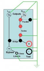
Okay, here goes: my version of the jig.
Edit: I attached the image (below) instead of hotlinking it. That should avoid any file-not-found issues if I redo my hosting.
Some notes: green is ground, black is signal, and dotted means it can be anything: open, shorted, or a resistor.
Unless otherwise indicated, jacks are banana terminals with a screwdown option. Most of the inputs and outputs are unbalanced 1/4" jacks (I have a T-S to RCA cable for hooking the bypass up to an amplifier). The input is a stereo 1/8" (3.5mm) to take advantage of the line out port on the soundcard. Left is all that will be wired. Right will remain open (ignored), as per Eric and Claudio's jigs.
I plan on soldering some dedicated 5, 10, and 20 Ohm jumpers as well as shorts for common testing modes.
Eventually, I may install Erics zener diodes to clamp down the output voltage just in case. I have an e-mail to the M-Audio tech support to see what is the max voltage the inputs can take.
Attachments
yours looks good. Simpler is always better in my book.
Actually I was wrong about burning out the soundcard.
for freq. measurements - the amp is never connected to the soundcard so no risk.
If I did amp calibration or calculate the transfer function of the xo (which I haven't yet), but I'm sure it can.
Cheers,
DAvid.
Actually I was wrong about burning out the soundcard.
for freq. measurements - the amp is never connected to the soundcard so no risk.
If I did amp calibration or calculate the transfer function of the xo (which I haven't yet), but I'm sure it can.
Cheers,
DAvid.
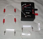
Okay, the jig is done and checked out okay. Design was revised a bit for space considerations.
When I moved into my house the previous owner left an assortment of HAM radio parts: jacks, knobs, pots, resistors, micro-screws, etc. So I ended up using most of the mini-plugs to be my test/bridge ports.
Every jack is grounded, as is the black banana test port. Grounds were run as close to the lid as possible. Signal leads were run off the lid and kept as far apart as possible. Internal wiring was 18 gauge solid.
Unfortunately my DMM test leads have a break in them and I can't seem to get accurate resistance readings, although open/short seem to work. I'll have to pick up some new test probes (I think the wires fatigued at the strain relief in the test probes and are barely hanging on -- a 5 Ohm resistor measured 17 and a 10 Ohm measured 23).
Oh, and I have an extra ground on the above powerpoint diagram. Only the jacks, the one test port, and the black banana plug should be tied to ground.
The leads shown there should be self explanatory. Two are shorts for bridging or bypassing the voltage divider section. The two resisors that are wired up are 10 Ohm, for most tests, and 10k Ohm for calibrating the sound card. I will also wire up voltage divider resistors once I figure out what the sound card can take.
On that front, I heard back from M-Audio regarding input impedance for the MobilePre:
3550 ohms instrument and Mic
4800 ohms for the stereo mic
Maximum input is -5.2 dBu
Finished around 11 last night, so no actual tests. I want to make sure my DMM is working right first anyway. Hopefully Rat Shack has replacement probes in stock.
Attachments
- Status
- This old topic is closed. If you want to reopen this topic, contact a moderator using the "Report Post" button.
- Home
- Loudspeakers
- Multi-Way
- Speaker Workshop Distortion Question