arc2v said:Some details on the amp I plan on using (in case you all think it will be awful).
It's a California Audio car amp powered by a radio shack regulated 12V power supply. I used this setup to power my subwoofers for a long time until I got an NHT SA-2 (I wanted more crossover control).
It's a MOSFET amp, but it's stable down to 2 Ohms. I believe it was 65W per channel RMS.
I'm sure the MobilePre won't have any trouble driving it. And I don't think you'll need to know exactly the output impedances of the line outs.
My bigger concern is the amp. I would consider not using it if it were a Class D amp. Even though the swiching frequency is a couple hundred Khz, the switching noise could get aliased into the inputs. Also, if it's a bridged amp, don't forget the 1/4" jacks are tip-sleeve...single-ended. You'll have to used the XLR connectors and tap a ground reference off the amp somewhere if it's bridged (but I've never tried this.)
Good luck....
I wasn't going to use it bridged, that's just how I used it for the subwoofer to get more power to woofer.
I believe it's an AB amp. The only weird amp I have is my NHT SA-2, which is like class G or H or something. Digital rail switching is what the manual said.
The current line of Profile/California amps is class AB. Mine is closest to the AP400, but without the variable crossover or bass boost:
http://www.crutchfield.com/S-GFydmL...p?g=120&tab=features_and_specs&i=489AP400#Tab
The Radio Shack power supply is 13.6V DC and has been a work horse. I like having it around to power various things I test or play around with, although it hasn't been used in a couple of years (I knew I kept it around, for a reason, though).
The current plan is to run a 3.5mm to Y rca from the MobilePre to the amplifier. Then using only the left channel, I'll send the branch loaded with the reference resistor AND test load back to the MobilePre line in (L) and the branch tapped just parallel to the test load back to the right channel. I'll verify voltages and put in a 5:1 or 10:1 if necessary.
Again, I think I have a lot of control with the gain knob, but like most amps with adjustable gain, there may be an ideal setting that maximizes signal and minimizes noise, but at too high a level to send back to the sound card (without a divider)
M-Audio only recommends 1.2V P-P max on the inputs.
Thanks again for the input!
Dreaded Open Circuit Error!
Okay, moderate success this evening.
I redid the jig with a voltage divider. 10k series and a 1k parallel.
Before I hooked up the jig I fed it a sine wave and set the levels and gain to get 1V P-P (I think my DMM reads peak to peak, not RMS).
Then I plugged it in and set the levels. 18k for the sine wave, 22k for the MLS.
I swapped in the 10 Ohm resistor and went for jig calibration. First I measured the resistance of the jig with the 10 Ohm resistor at the amp. 11 Ohms, so things seemed wired correctly. I put the 5 Ohm resistor in place and got about 16 Ohms at the amp, so everything seemed wired correctly.
When I went to calibrate I got the dreaded Open Circuit Error message, saying it did not appear to have a load resistor (it did, the 5.1 Ohm one). I tried swapping channels to no avail.
Another observation, even though the voltage was 1V, both resistors got really HOT! I almost burned myself adjusting the jig. P=V^2/R=1/10, so 1/10th of a Watt made it that hot??? Is this normal? I forgot to measure voltage across the resistor (just the output terminals to the sound card), but it can't be higher than that.
I even lowered the voltage to 0.7 (system volume at less than half) and it still got hot after attempting to calibrate. The 5 Ohm resistor was hot as well. So I'm concerned, but am pretty sure nothing is wired wrong.
Second question: any guidelines for a voltage divider? 10:1 seems to be working for me, but should I use 1k to 100, 10k to 1k, 4.7k to 470?
Last question: Claudio mentioned using 47k as the sound card impedance. The M-Audio folks told me the input impedance is 3500 Ohms, which seems REALLY low. Which value should I use? I plan on using the conversion formula in the SW manual to include the voltage divider. Could this be the cause of my Open Circuit error message?
Thanks again for all the help. I had a family event and couldn't spend all the time I wanted to testing this. I'm going to dive in and hopefully finish this all tomorrow night after work.
Re: Dreaded Open Circuit Error!
1k and 100 ohm is fine.
If M-audio told you 3500 ohm, use it: consumer SC usually are 47k, pro card 10k, your 3500. Just do the calculation for the voltage divider and write the value in the SC input impedance window.
The open circuit problem, in my experience, is always caused by a bad connection in the jig.
arc2v said:[
Second question: any guidelines for a voltage divider? 10:1 seems to be working for me, but should I use 1k to 100, 10k to 1k, 4.7k to 470?
Last question: Claudio mentioned using 47k as the sound card impedance. The M-Audio folks told me the input impedance is 3500 Ohms, which seems REALLY low. Which value should I use? I plan on using the conversion formula in the SW manual to include the voltage divider. Could this be the cause of my Open Circuit error message?
[/B]
1k and 100 ohm is fine.
If M-audio told you 3500 ohm, use it: consumer SC usually are 47k, pro card 10k, your 3500. Just do the calculation for the voltage divider and write the value in the SC input impedance window.
The open circuit problem, in my experience, is always caused by a bad connection in the jig.
Thanks Claudio. My "jig" now is just a 12 position screw-down strip with stuff everywhere (it's hard to make a voltage divider like that).
I was planning on soldering it up after I tested it. It very well could have a bad connection, although the resistances and continuity seem to check out every time I test them (and loop works just fine).
I also figured out why my resistors were overheating: I'm an idiot -- the voltage divider is AFTER the circuit, so the resistors were seeing 10-16V, not 1V RMS. So I was asking them to dissipate 5-10W of power, which is their limit. I'll recheck them to make sure they aren't damaged.
So I need to lower the volume a lot and make sure the input voltage is much lower, so much so that I might not even need the voltage divider anymore.
That, or I'll have to put a voltage divider in front of the circuit to limit the amount of current the reference and test resistors see.
I'm going to make a model of the circuit in Matlab (mesh current using matrix operations) so I can verify what all the various voltages should be, so I can test the jig more thoroughly.
Thanks again.
Success!!!
Success! The prototype jig is up and running. Right now it is just twisted leads and screw down terminals, but I plan on soldering something together tomorrow.
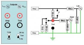
To make it work, I used my amplifier, which puts out 16V at minimum gain and max output volume. I made a 1/16 voltage divider sized such that the divider's impedance was 10x that of the sound card input. It ended up being 6k for R1 and 400 for R2. It wasn't ideal, but I could do it with resistors I had. I used 1/4 watt, 1% metal film resistors for this and the two dividers measured spot on.
Then it was just wiring everything up.
Set the levels a bit lower, 15k sine wave. Did channel difference and set card impedance, then calibrated the jig. Spot on calculation of the reference resistor, and for a few resistors to test.
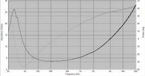
I also ran a free air impedance plot of one of my Dayton Drivers (attached). I think it looks good, unless you all think it looks too noisy.
Big thanks to everyone who helped me with this. Once I get an actual soldered jig in place, I'll actually get to start designing speakers
Success! The prototype jig is up and running. Right now it is just twisted leads and screw down terminals, but I plan on soldering something together tomorrow.
To make it work, I used my amplifier, which puts out 16V at minimum gain and max output volume. I made a 1/16 voltage divider sized such that the divider's impedance was 10x that of the sound card input. It ended up being 6k for R1 and 400 for R2. It wasn't ideal, but I could do it with resistors I had. I used 1/4 watt, 1% metal film resistors for this and the two dividers measured spot on.
Then it was just wiring everything up.
Set the levels a bit lower, 15k sine wave. Did channel difference and set card impedance, then calibrated the jig. Spot on calculation of the reference resistor, and for a few resistors to test.
I also ran a free air impedance plot of one of my Dayton Drivers (attached). I think it looks good, unless you all think it looks too noisy.
Big thanks to everyone who helped me with this. Once I get an actual soldered jig in place, I'll actually get to start designing speakers
Attachments
Big thanks for all the help.
I mistyped up there about the divider impedance, it is 1/10th the soundcard input impedance.
I have a new enclosure box and hope to build it this weekend. It's a lot simpler and now that I've played around with calibrating a lot, I like the idea of flipping a switch to go between modes.
I mistyped up there about the divider impedance, it is 1/10th the soundcard input impedance.
I have a new enclosure box and hope to build it this weekend. It's a lot simpler and now that I've played around with calibrating a lot, I like the idea of flipping a switch to go between modes.
Attachments
- Status
- This old topic is closed. If you want to reopen this topic, contact a moderator using the "Report Post" button.
- Home
- Loudspeakers
- Multi-Way
- Speaker Workshop Distortion Question