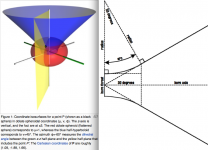
Orthogonal Coordinate System of an OS horn
Wikipedia does a fine job presenting this:
Oblate spheroidal coordinates - Wikipedia, the free encyclopedia
The oblate spheroid surfaces represent the isophase wave front and the hyperbolic cylinder represents the horn boundary that encloses them. For finite horns this all breaks down when the mouth is reached and reflectance takes place, particularly at the lower frequency bound of the horn's pass band.
WHG
That's a nice synopsis.
Nothing actually breaks down from reflections because it is possible to calculate the reflections and how the reflected waves propagate back down the waveguide. And this can be done at any frequency.
This calculation will tend to run away from you if the ends are very reflective because more and more of the waves will be transferred into the higher order modes. The higher order modes get more and more difficult to calculate and sooner or later this calculation becomes intractable.
But if the mouth is flared and the reflections are lower then the calculation are not so difficult. I have done these calculations before. there is not much to learn from them however. What is most important is knowing what the wavefront is at the mouth and this calculation is fairly straightforward as my book shows.
I find the calculation on the right more straightforward than the calculation on the leftBut if the mouth is flared and the reflections are lower then the calculation are not so difficult. I have done these calculations before. there is not much to learn from them however. What is most important is knowing what the wavefront is at the mouth and this calculation is fairly straightforward as my book shows.
") .
.Attachments
But the one on the left is exact and the one on the right in error. And since my molds are done numerically whats the difference? Why not just do it right?
The one on the right was done strictly because the one on the left is harder to draw in the drafting packages of old (a modern one can do the one on the left just as easy as the one on the right).
The one on the right was done strictly because the one on the left is harder to draw in the drafting packages of old (a modern one can do the one on the left just as easy as the one on the right).
Pick
On the left you have Frehaffer (Salmon) [1]/Geddes on the right you have Hughes/Peavey approximation [1]. Take your pick; one is
essentially within the manufacturing tolerances of the other.
WHG
[1] http://dspace.mit.edu/bitstream/handle/1721.1/45994/35167649.pdf?sequence=1 (EG this may interest you)
[2] http://aaassets.peaveyelectronics.net/pdf/qwp1.pdf
I find the calculation on the right more straightforward than the calculation on the left
On the left you have Frehaffer (Salmon) [1]/Geddes on the right you have Hughes/Peavey approximation [1]. Take your pick; one is
essentially within the manufacturing tolerances of the other.
WHG
[1] http://dspace.mit.edu/bitstream/handle/1721.1/45994/35167649.pdf?sequence=1 (EG this may interest you)
[2] http://aaassets.peaveyelectronics.net/pdf/qwp1.pdf
A Contrary View
WHG
[1] http://levien.com/phd/euler_hist.pdf
Thanks! Comments follow:That's a nice synopsis.
While we can calculate it, the wave is propagating in the wrong direction. That is contra to a loudspeaker horn's mission. Our choice to mitigate this problem is to make the mouth perimeter [p] much larger than otherwise required (bigger horn where [p] >> [c]/[fl]) or depart from the very coordinate system that is yielding the precision we desire and use something foreign to form horn lips of an arbitrary non-OS geometry.Nothing actually breaks down from reflections because it is possible to calculate the reflections and how the reflected waves propagate back down the waveguide. And this can be done at any frequency.
This finding supports the conjecture that horns of infinite extent, that require mouth truncation to make them real, are a bad idea for loudspeaker applications. Alternatively, curves such as a segment from Euler’s spiral [1] might be a superior choice. Here boundary curvature gently increases with curve length to form a smooth transition to free space from the confines of throat aperture of a compression driver. One could argue that this approximation comes closer to meeting the mission of a loudspeaker horn where unlike that for a musical instrument, reflectance is to be avoided. We do not want to trap acoustical energy within the horn; we want all of it to leave!This calculation will tend to run away from you if the ends are very reflective because more and more of the waves will be transferred into the higher order modes. The higher order modes get more and more difficult to calculate and sooner or later this calculation becomes intractable.
Again the added mouth flare constitutes an arbitrary departure from the geometry of the horn body and will be ‘seen’ by the outbound wave as an acoustical discontinuity. For any horn, mouth reflectance can be calculated once the boundary conditions have been established, irrespective of whether OS conforming or not.But if the mouth is flared and the reflections are lower than the calculation is not so difficult. I have done these calculations before. there is not much to learn from them however. What is most important is knowing what the wavefront is at the mouth and this calculation is fairly straightforward as my book shows.
WHG
[1] http://levien.com/phd/euler_hist.pdf
On the left you have Frehaffer (Salmon) [1]/Geddes on the right you have Hughes/Peavey approximation [1]. Take your pick; one is
essentially within the manufacturing tolerances of the other.
WHG
[1] http://dspace.mit.edu/bitstream/handle/1721.1/45994/35167649.pdf?sequence=1 (EG this may interest you)
[2] http://aaassets.peaveyelectronics.net/pdf/qwp1.pdf
WHG
That is indeed a fascinating paper and I was not aware of its presence.
I am not sure that I agree with you "manufacturing tolerances" however. I hold mine much closer than the differences in the two contours. And studies that I have done indicate that the throat accuracy is the most important part.
Is this difference significant? I have no idea, I have never done the Peavy design, I never saw any point to. I did object to their claiming some new "invention" however. It was not new it was just a way to avoid a patent infringement. I worked with them at or near that time.
We do not want to trap acoustical energy within the horn; we want all of it to leave!
There is an entire section in my book on why we don't want mouth reflections and how best to mitigate them with a flare. Nothing that you are saying here is new (to me at least). We don't want any mouth reflections - period.
The best mouth flare differs in the "free" case from the "baffled" case. I only use the baffled case so the Euler curve is not appealing. One can hypothesize on the idea flare into a baffle, but in the end they all look an awful lot like just a radius.
In my waveguides, the complete lack of any extraneous impedance bumps on the drivers electrical input impedance is a pretty good indication that the mouth flare works well.
There is one frequency at which the reflections at the mouth edges creates a standing wave across the mouth - but not back down the horn - and this results in the axial hole seen in a round waveguide.
How the mouth is handled is critical to any design and the place where I see most horns fail.
MOAS etc.
The baffle is finite as well, so yet another diffraction edge is to be encountered.
Why not integrate the two?
In the case of in-wall installation, where the baffle is materially infinite, spiral segment transform may still be used. Have a look at how they are used in roadway design for some ideas [1].
[1] http://www.oregon.gov/ODOT/HWY/GEOMETRONICS/docs/highwayspirals.pdf
Ear plugs still remain standard issue when working there. See [2] below for a fellow who forgot his.
WHG
I know that most of my prose here are a "choir preach" for you or maybe the source of an eye-roll as well; but here, the audience is much more diverse, so I try to keep it understandable to all.There is an entire section in my book on why we don't want mouth reflections and how best to mitigate them with a flare. Nothing that you are saying here is new (to me at least). We don't want any mouth reflections - period.
That is Hughes’ approach to the horn neck as well. I thought other methods were preferred.The best mouth flare differs in the "free" case from the "baffled" case. I only use the baffled case so the Euler curve is not appealing. One can hypothesize on the idea flare into a baffle, but in the end they all look an awful lot like just a radius.
The baffle is finite as well, so yet another diffraction edge is to be encountered.
Why not integrate the two?
In the case of in-wall installation, where the baffle is materially infinite, spiral segment transform may still be used. Have a look at how they are used in roadway design for some ideas [1].
[1] http://www.oregon.gov/ODOT/HWY/GEOMETRONICS/docs/highwayspirals.pdf
I am not surprised and suspect the design has a lot of lab-work sweat all over it.In my waveguides, the complete lack of any extraneous impedance bumps on the driver’s electrical input impedance is a pretty good indication that the mouth flare works well.
Ear plugs still remain standard issue when working there. See [2] below for a fellow who forgot his.
Regards,There is one frequency at which the reflections at the mouth edges creates a standing wave across the mouth - but not back down the horn - and this results in the axial hole seen in a round waveguide.
How the mouth is handled is critical to any design and the place where I see most horns fail.
WHG
Attachments
It seems that when we look at various design approaches, it's best to evaluate from many expects in terms of measureable result. For example, directivity, distortion, amplitude & phase, CSD, etc.
Up to now, I think wave guides definitely have god potential, but the profile really depends on driver characteristics.
Up to now, I think wave guides definitely have god potential, but the profile really depends on driver characteristics.
Is there a difference between a "spiral" and an involute.
Involute - Wikipedia, the free encyclopedia
Involute - Wikipedia, the free encyclopedia
Yes,
but it can be a sprial as well.
Logarithmic Spiral Involute -- from Wolfram MathWorld
Is there a difference between a "spiral" and an involute.
Involute - Wikipedia, the free encyclopedia
but it can be a sprial as well.
Logarithmic Spiral Involute -- from Wolfram MathWorld
Last edited:
So considering a 6.5" cone midrange, what size WG would typically offer an ideal directivity match to say 3-3.5khz?
You would have to post the polar response of the midrange, otherwise its just a guess. I don't like to guess.
The only waveguide parameter that you have at your disposal is the coverage angle (the throat radius is fixed by the compression driver). This is set to match the angle of coverage of the driver just below the waveguides operating band.
The other option, which is what I do, is make a waveguide, measure it and the woofer and set the crossover point at where the two match.
But the question specified the crossover point, at that frequency the "midrange" polar pattern will be fixed, so the only option is to modify the waveguide design to match the midrange at the specified crossover. That's not the way that I would do it.
- Home
- Loudspeakers
- Multi-Way
- Geddes on Waveguides