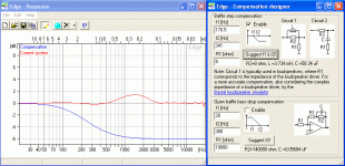
I created my baffle in The Edge and it gave me the data. Now I just need to know what to do with this information. I guess I need an 8ohm resistor, 3.7mH inductor, and 58uF cap? Then wire it as shown in circuit 1. Also, what value should I use for R1, and how does this effect the circuit and the sound?
Attachments
From the output from the CD/DVD player, and plug into the input of the active filter from the design derived from Edge software that will do the trick.
From the output of the Edge active filter you plug into the input of the CX2310, that will take care of the BS.
The above is a general approach, some tweakings of components may be necessary depending on other factors which I am not aware of. Sorry I cannot design for you.
From the output of the Edge active filter you plug into the input of the CX2310, that will take care of the BS.
The above is a general approach, some tweakings of components may be necessary depending on other factors which I am not aware of. Sorry I cannot design for you.
Hi,
Normally you include BS in the bass mid crossover, it is not
compensated independently, try following this methodology :
http://www.rjbaudio.com/Audiofiles/FRDtools.html
 /sreten.
Normally you include BS in the bass mid crossover, it is not
compensated independently, try following this methodology :
http://www.rjbaudio.com/Audiofiles/FRDtools.html
Hello GuyPanico,
You do not need both the inductor and capacitor, the program is showing you two different possibilities. Circuit 1 is typically used in a passive filter, while circuit 2 would be used in an active filter.
To use circuit 1, you enter the Re of the driver in R1. This will be somewhere around 5.5 - 6 ohms for an 8 ohm nominal driver. You will also need a zobel.
To use circuit 2, you enter the input impedance of the amplifier in R1. This will be somewhere around 10,000 - 100,000 ohms.
As sreten has mentioned, normally you do not use a separate BSC circuit. Instead, you integrate it into the midrange filter, and use an LPAD for the tweeter. The only time I've seen seperate BSC filters was for fullrange speakers with no lowpass filters.
If you have never built a speaker before, I highly recommend you copy a project posted somewhere on the internet. I'm into my third design, and my projects still don't measure like they model. It's getting better, but I'm still off by 3db on a regular basis.
Dan
owdi said:
To use circuit 2, you enter the input impedance of the amplifier in R1. This will be somewhere around 10,000 - 100,000 ohms.
Is that really true? I thought that it was mainly down to personal preference and convenience. I know that the choice of this resistor would have an impact on noise but that's as far as my knowledge goes.
Can anyone explain briefly what determines R1? The input impedance of the opamp would already be extremely high and the resistance of the feedback loop is at least 2 x R1. Help!!
Kind regards,
Martin.
Thanks for all the help so far.
I'm still trying to understand how to impliment the circuit. The speakers i'm working with are going to be 2 way, active and biamped. For circuit 2, I would place the 8ohm resistor and 58uF cap on the signal wire going to the active crossover?
1) How do you measure the proper impedance?
2) I'm not very good with diagrams yet, how exactly is the circuit wired?
Thanks everyone for your patience!
- Status
- This old topic is closed. If you want to reopen this topic, contact a moderator using the "Report Post" button.
