The new thread about trying to simulate a bass-reflex boss using LTspiceIV is here :
http://www.diyaudio.com/forums/mult...d-box-loudspeaker-spice-model-aes-1991-a.html
http://www.diyaudio.com/forums/mult...d-box-loudspeaker-spice-model-aes-1991-a.html
I've been amusing myself with manual calculations to try to find a suitable bass driver for a bass reflex system, with a f-3 of 30 Hz. I've found a few that gives satisfying Vb and vent tuning values, but when I come to calculations of the vent diameter and length, my luck is out. I've been trying with dual 10" and 12" drivers.
I get results in the 5-6" for the diameter, and at least around 30" for length. Can it be due to that I use double the Vd value, as I do for Vas when calculating Vb value for the box?
I've used the following formulas, given in Basta! + Dickason's formulas for a SBB4 in LDC. (For vents, I've tried those in LDC and some others, result the same):
1. Öhman
Vb = Vas/1.1 x (Qts/0,40)^3/1+0,4xViso
fp = fs x (0,42/Qts)
2. Keele
Vb = Vas x 15 x Qts^2,87 / 1 + 0,4 x Viso
fp = fs x 0,42 x Qts^-0.9
3. Margolis/Small
Vb = Vas x 20 x Qts^3,3 / 1 + 0,4 x Viso
fp = fs x 0,42 x Qts^-0,96
I've used a Viso value of 20% (Viso = amount of lining material in comparison with total volume)
Suggestions for f-3 calculations for the formulas above?
Suggestions for vent calculations?
Suggestions for two 10" or 12" that might give a f-3 around 30 Hz in a box with a Vb of at the most around 100 liter?
I've been amusing myself with manual calculations to try to find a suitable bass driver for a bass reflex system, with a f-3 of 30 Hz. I've found a few that gives satisfying Vb and vent tuning values, but when I come to calculations of the vent diameter and length, my luck is out. I've been trying with dual 10" and 12" drivers.
Suggestions for two 10" or 12" that might give a f-3 around 30 Hz in a box with a Vb of at the most around 100 liter?
Why only bass reflex? Sealed boxes roll of much slower and hence with a F3 or say 45Hz might offer lower in room (with room gain).
Suggestions would the SEAS L22RNX/P (bass reflex), W26FX01 (sealed), or Peerless XXLS subwoofers (sealed) see links below.
THE ART OF SOUND PERFECTION BY SEAS - H1252-08 L22RNX/P
THE ART OF SOUND PERFECTION BY SEAS - E0026-08S W26FX001
Comparing some bass-reflex arrangements.
Monacor SPH-210 is ruled out because of 50 Hz -3dB point.
Monacor SPH-225C is ruled out because of 51 Hz -3dB point.
Seas W26FX001 E0026 is ruled out because of Box volume 60.7 litre.
Monacor SPH-200KE gives a 29 Hz -3dB point in a 25.8 litre box.
Amazing for such a small box.
Problem may be the port lenght, 182mm long with 50mm diameter.
Seas L22RNX-P H1252 gives a 31 Hz -3dB in a 36.5 litre box.
Port is compact : 119mm long with 50mm diameter.
Monacor SPH-212 gives a 28 Hz -3dB in a 48.6 litre box.
Port is very compact : 98mm long with 50mm diameter.
Attachments
Last edited:
Ooops ! I agree there is a problem in my post #103 & #105. I'll redo the calculations checking with WinISD beta. In the meantime please ignore post #103 & #105. Please apology.
Also remember that a sealed box with an F3 of say 45Hz might have as much in room response as a bass reflex box with an F3 of 30Hz. The SEAS W26FX001 suggested would give you a F3 of about 45-50Hz in a 35-37 liter SEALED box. The SEAS L26RFX/P also offers similar sealed box perfomance and is half the cost of the W26.
You should maybe look at F3 and F10 numbers to determine which woofer system works best in your room.
We get some Wavecor woofers in India. I dont know if you get them where you are but they perform well in small boxes with passive radators. Yo can check out their 10" and 12" woofers here.
http://www.wavecor.com/
Last edited:
Big cone doesn't mean deep bass.
No, not necessarily, but it does help moving air when going deeper.
Why only bass reflex? Sealed boxes roll of much slower and hence with a F3 or say 45Hz might offer lower in room (with room gain).
I would prefer a sealed solution, but I have not been able to find one as yet that I thought would be usable. But if f-3 dB at 40 Hz is what makes it, I know a few, plus the ones suggested already in this thread. I've heard of room gain, but I was not aware that a sealed box with a higher f-3 dB than a vented box with a lower f-3 dB would equal, or better the vented box.
You should maybe look at F3 and F10 numbers to determine which woofer system works best in your room.
We get some Wavecor woofers in India. I dont know if you get them where you are but they perform well in small boxes with passive radators. Yo can check out their 10" and 12" woofers here.
Wavecor speaker innovations
Now that you mention it, I've seen it a few times before, but not that often, that checking the F10 numbers as well is a very good suggestion, due to the fact that F3 do not tell you that much, was the explanation, if I recall correctly.
We do have Wavecor in my area, and I've checked them up earlier, but I will do it again, and I'm not used to radiator solutions at all, never looked at that solution at all. If someone could just outline the major difference between reflex and radiator, I would be much obliged.
Small box is not that important, if by small you mean something less than around 100 liter in total for the woofer section. Smaller would be nice (WAF), but I think I can handle up to 100 lit.
I would prefer a sealed solution, but I have not been able to find one as yet that I thought would be usable. But if f-3 dB at 40 Hz is what makes it, I know a few, plus the ones suggested already in this thread. I've heard of room gain, but I was not aware that a sealed box with a higher f-3 dB than a vented box with a lower f-3 dB would equal, or better the vented box.
We do have Wavecor in my area..If someone could just outline the major difference between reflex and radiator, I would be much obliged.
It usually depends on the room and the location of the speakers within that room. In many rooms the speakers get pushed against the rear wall. In such cases if the speaker does go very deep there will be a lot of nodes excited and also a lot of room gain (much of it uneven) and this can lead to lumpy bass which in my opinion is worse than too little bass.
There is no "RIGHT" solution. The room-speaker interaction is what determines the response of a loudpspeaker. Becuase bass has longer wavelenghts it's interaction with the room is more prominent. Dont aim for flat response (+/-3 db as advertised by many manufactuers in their catalogs). The room can add +/- 10db with ease so all those flat response curves are really not worth the paper they are written on. Which is why I discussed F10 numbers earlier.
I have lived on 3 continents (4 countries) and a variety of dwellings from a studio apartment in NYC (with flimsy sheet rock walls) to a large (wooden) house in the boonies with vaulted ceilings to a brick and concrete apartment and once even had a square room (exactly 16ft square). Each dwelling offered it's own challenges. As DIYers I believe it is our abilities to adjust for these "challenges" (as well as adjusting the sound to our ears) that makes DIY such a pleasurable and fulfilling pastime/hobby.
Passive radiators have their uses. If port lengths are too long a PR is often a viable option. Another option is that one can avail of Milo Nestorovic's concept of using cones of 2 different sizes (say a 10" woofer mated to a 12" PR). Adjusting the mass of the PR is also easier than adjusting a port length so in that way a PR is easier to tune to a room that a bass reflex speaker. However a PR has a fixed (static mass) while th mass of air inside a bass reflex port is not nesscarily so and this can pose it's own problems (transient response is not as good as a (SBB4 or even QB3) ported box). Wavecor's website has sample boxes and their transient response curves for your reference. see link below for more.
Audio Innovation - by Dan Marx www.danmarx.org
Before starting out I would advise you to try out a few of your friends' speaker systems in your room and at least determine which systems sound best. From the late 70s to today I must have "gone through" over a dozen speaker systems (from Philips, KEF, Volt/Rogers, JBL, JBL/UREI, Gold Sound, Vifa, Focal, Dynaudio, Morel/Focal, Peerless/Dynaudio, Focal/Morel/JBL, ScanSpeak, Audio Concepts, etc...) and each worked within it's own limiations and enviroment. I have also lived with friends' speakers from Klipsch, Polk, Fried, Vanderstee, Theil, Snell, AR, Infinity, etc.. and each time realised that DIY is a much better option even if you dont save any money by going DIY.
Good photographers have a clear idea of the picture they are going to take before even raising the camera to their eye. Similarly you need to determine what you want your system to sound like before shortlisting the drivers.
Hope this helps.
Last edited:
Which is why you often see the use of double woofers, making a WMTMW And then it gets really tall
Dual woofers is my intention. Difference between WMTMW & WWMTM?
any reason the SEAS CA26RE4X has not been short listed. It's EBP ratio would suggest bass reflex.
It's due to a couple of parameters that in my limited view makes it less attractive: low powerhandling, VC only 39mm, Xmax only 4mm one-way, too high VC inductance (3.08 mH). All together, I feared that it woun't be able to play loud enough.
The SEAS W26FX001 suggested would give you a F3 of about 45-50Hz in a 35-37 liter SEALED box.
We get some Wavecor woofers in India. I dont know if you get them where you are but they perform well in small boxes with passive radators.
-My rough calculations indicate F3 at 40 Hz with Vb = 108 lit.
-the Wavecors have a very limited frequency range with the upper level recommended at 300. I will need some headroom as well above that.
Before starting out I would advise you to try out a few of your friends' speaker systems in your room and at least determine which systems sound best.
Good photographers have a clear idea of the picture they are going to take before even raising the camera to their eye. Similarly you need to determine what you want your system to sound like before shortlisting the drivers.
I don't have that many friends, and non has speakers coming even a tiny bit of the way of what I'm aiming for, that is, they don't care as long as something close to music comes out of the speaker.
In that case, I'm the equivalent to a fotographer. I ""know"" exactly what I'm aiming for (but please don't ask me what it is, or how I'm thinking of getting there.
After having re-read this thread today, I would like to apologize for having been so sloppy with regards to the details of all your kind posts. I have and will even more later, pay attention to the details and now have more insight than before, and after going through the details even more at home later, will gain even more.
I also have to digest all the "pivotal" papers of Thiele and Small + a few more before I'll feel comfortable starting the simulation efforts, and if all goes according to plan, before the new year, I will end this thread to start my long (by me) awaited project thread instead.
At this stage you would be better using SpectraLab 4.32, put a medium driver into a standard 10 litre closed box, measuring the phase and amplitude on-axis and off-axis, horizontal and vertical. Then you'll understand that every medium driver needs a tailor-made approach for mating it with a tweeter. I guess that you want the highest quality so even before attempting equalizing a medium driver, you first need to concentrate on the off-axis radiation pattern, and basing on this, set the crossover frequency.
For instance, if you are using a 130mm aluminium medium driver, you may be horrified by the agressive resonance peak at 8 kHz, but on the other hand you should be happy seeing that the lobing only starts at 8 kHz. Which means that after equalizing the driver (removing the amplitude peak), a 4 kHz crossover frequency can be applied. If you use a 1st order lowpass filter, the directional lobes will show at -6dB, which is decent. And you'll get a phase accurate system if you manage to filter the tweeter in such a way that it delivers a 1st order highpass acoustic transfer function. Or you may reach a -20 dB muting of the directional lobes using a 4th-order Linkwitz-Riley crossover, but the disadvantage is that you'll lose the phase accuracy.
For instance, if you are using a 130mm Kevlar medium driver, you may be delighted seeing that the frequency response looks linear untill 8 kHz or so, without any resonance peak. But beware the directional lobes, with such drivers they can appear as soon as 4 kHz. Which means that you would be better lowpass filtering at 2 kHz. Or you can tweak the driver, adding a phase plug. With some patience you can shift the lobing to a higher frequency like 6 kHz or so.
Amazing results can be attained for a cheap price using Monacor CRB-100CP car speakers. Those are 100mm carbon midbass drivers fitted with a cheap tweeter inside. Pull the tweeter out, replace it by an optimized phase plug. Then, measure how far in frequency the lobing is occurring, and realize how easy they can be filtered in order to get an essentially flat output with a smooth roll-off above 8 kHz.
When you are happy with such single driver, do the same using a d'Appolito MTM configuration, with minimal distance between the two medium drivers.
Dual woofers is my intention. Difference between WMTMW & WWMTM?
-My rough calculations indicate F3 at 40 Hz with Vb = 108 lit.
given this link
Speaker Box Enclosure Designer / Calculator
I get 50 liters for 40Hz (Qtc of 0.7) but if you bump Qtc to 0.85 then you can get 42Hz from 33 liters.
I have never been a big fan of MTM . I find that the sweet spot though tighter is narrower and since I often listen with my wife my requirement is always for a sweet spot that allows both of us to listen at the same time. MTMs I have built....
a. Peerless TP165R/KO10DT
b. Focal 8N515/Morel MDT33 mated to a JBL 2245H in a 10 cu. ft. (B460) ported box my wife called a 'coffin' (per channel)
c. Dynaudio 15W75/D28af (Gemini) mated to a subwoofer using 2 Peerless 831727 (10") in a 3 chambered bandpass (per channel)
d. ScanSpeak 18W8546/2905-9900 (revelator) mated to a 5 cu. ft. box housing 2 Audio Concpets DV12s (per channel)
Last edited:
At this stage you would be better using SpectraLab 4.32, put a medium driver into a standard 10 litre closed box, measuring the phase and amplitude on-axis and off-axis, horizontal and vertical.
- Why not both of them at the same time in their coming MTM configuration, are one not interested in the combined response as well? I'll be using two Monacor MSH-116/4 (124mm) 4" mids. (Answered below, I've just noticed)
For instance, if you are using a 130mm aluminium medium driver, you may be horrified by the agressive resonance peak at 8 kHz, but on the other hand you should be happy seeing that the lobing only starts at 8 kHz. Which means that after equalizing the driver (removing the amplitude peak), a 4 kHz crossover frequency can be applied. If you use a 1st order lowpass filter, the directional lobes will show at -6dB, which is decent. And you'll get a phase accurate system if you manage to filter the tweeter in such a way that it delivers a 1st order highpass acoustic transfer function. Or you may reach a -20 dB muting of the directional lobes using a 4th-order Linkwitz-Riley crossover, but the disadvantage is that you'll lose the phase accuracy.
- I've tried to check lobing with Xdir (tolvan.com) to get a rough idea of what to expect, but I'm not even shure of how to think regarding the woofer and tweeter settings (in dB) that you can do, so I'm very doubtful about my conclusions, to be polite to myself. Do you mean that I am to check the lobing issue in some software after measuring phase and amplitude in the 10 lit. box?
- You suggest SpectraLab, but I'm not that very keen on buying additional software at this time, too many other items that's needed for the project at this time, so I will check what my intened measurement software can do. and SL's home page does not display the price, you have to e-mail.
When you are happy with such single driver, do the same using a d'Appolito MTM configuration, with minimal distance between the two medium drivers.
- Will do. I'm gonna make me a box with detachable baffles, I think, so that I don't have to redo the box as well. The C-C for the mids is 180mm when using my Morel MDT40 tweeters, or 198mm if I do the baffle to be able to fit a 72mm Morel, or other tweeter as well as suggested earlier.
I get 50 liters for 40Hz (Qtc of 0.7) but if you bump Qtc to 0.85 then you can get 42Hz from 33 liters.
- Well, quite a difference. I'll check out some drivers more thoroughly when I start usning Basta! in a near future.
I have never been a big fan of MTM . I find that the sweet spot though tighter is narrower and since I often listen with my wife my requirement is always for a sweet spot that allows both of us to listen at the same time.
- I am aware that not all is that satisfied with the MTM config. However, now that I have 4 mids, I am going to give it a first try. And the sweet spot problem or yours is mote in my house. My wife tends to prefer to be gone from the house when I play my music (not that much musical taste in common)
When are you supposed to use the IEC-baffle instead of measuring in free air when testing raw drivers? My impression is that DIY seems to do free air, but when reading many "scientific papers", oftentimes they seem to use the IEC-baffle, but I might be mistaken?
My next hurdle is the measuring mic., that I fear it is gonna take a while before I can buy it, so I guess I'll have ample time to simulate what can be simulated, and also to build some test boxes in advance.
I also have to fill some gaps regarding lobing, phase and the effects of various filter slopes etc, etc, etc, etc.
I would usually use free air for the Thiele Small parameters but the baffle for measuring frequency response. It doesn't make much sense to measure that in free air as the front to back cancellations would be intrusive and pointless.
I don't make an IEC baffle for testing and don't plan to. I'm more likely to do such measurements on a real baffle, noting the frequency that is usually referred to as the baffle step frequency (but not trying to be too exact), so I can note this is not caused by the driver.
With regards to the mike, I used to use a Radio Shack level meter. I don't know whether they still make these. It had an RCA socket on the side so I could plug it straight into a computer. It acted like a simple mike and preamp package and was relatively cheap and easy to find.
With regard to the slopes, theory and practice are often quite different when you consider the way a filter responds to a complex impedance and an already jagged frequency response. If you can take good measurements of response, phase, impedance and its phase (4 plots per driver), you can simulate a good starting point.
You won't see nor understand anything if :
- you don't invest a few minutes downloading SpectraLab 4.32.
- you don't invest a few minutes reading SpectraLab 4.32 user manual to understand why it is so important to use a twin-channel measurement system able to measure the amplitude and phase in realtime using a pseudo-random continuous signal like a pink noise as reference
- modality : Left "divided by" Right
- setting : FFT 8192 , averaging 8 FFTs
- Left Line out = pink noise out (to power amp input AND also to Right Line In)
- Left Line IN = amplified mike signal
- Right Line IN = pink noise out (connect to Left Line OUT)
- Generator : activated in pink noise modality
A decent measuring mike can be done using :
- a 2-terminal electret capsule
- loaded by 3k3
- with a supply of 3x 1.5 AA batteries (4.5V) or 3x 1.2V AA NiMH cells (3.6V)
- with a mike preamp made of a BC459C common emitter layout with 680K automatic polarization, 3K3 load on the collector and 330R on the emitter.
- plus decoupling and audio coupling capacitors
Such mike preamp gives 18dB voltage gain and is compatible with any decent Line IN.
You need to put your driver in a box.
This way, instead of measuring IEC performance and lobing (that you don't care) or free air performance and lobing (that you don't care), you will measure the actual performance and lobing using the final box. Make various boxes with various proportions like wide or tall, or "gold number" proportions, then put the driver in the middle, or specifically NOT on the middle, and you'll know everything you need to know about a medium driver sitting into an enclosure.
Cut the dust cover, and add a phase plug if you dare ...
Repeat the measurements ...
When you feel happy, keep the same box and equip it with two drivers in a MTM d'Appolitio configuration. Measure the effect.
Get a tweeter in the middle. Highpass it using a capacitor, and lowpass the drivers using a coil. See the crossover issue. Need to recess the tweeter to compensate for the transmission delay. Or put the medium drivers forward. Normally you should get a decent blend, with a linear phase.
Then decide if you want to keep such complicated faceplate, or want to get a flat faceplate.
If you want to get a flat faceplate, you need to add electronic delay to the tweeter.
While doing the experiment, try to correlate what you hear (the pink noise) with what seems to be a good setup. This way, after a while, your ear will tell you faster than the computer screen, when you reach an optimum.
The optimum is a pink noise perceived as smooth, somewhat warm, not grainy, not agressive, without any tonal dominance.
If you can keep such perception between - 30 degree lateral and + 30 degree lateral, then you won. There isn't any sweet spot in the lateral plane.
Then, check what's happening in the vertical plane. Be happy if you reach a -15 degree + 15 degree homogeinity in the vertical plane.
You won't see nor understand anything if :
- you don't invest a few minutes downloading SpectraLab 4.32.
- you don't invest a few minutes reading SpectraLab 4.32 user manual to understand why it is so important to use a twin-channel measurement system able to measure the amplitude and phase in realtime using a pseudo-random continuous signal like a pink noise as reference
You need to put your driver in a box.
This way, instead of measuring IEC performance and lobing (that you don't care) or free air performance and lobing (that you don't care), you will measure the actual performance and lobing using the final box.
You really know how to keep me busy with trying to learn new concepts and techniques just when I thought I was about to dig down in what was previously discussed. However, I'm a "knownledge addict" so I don't complain.
However, for SpectraLab, their home page sucks, and hints on the web suggests that they might not be operating any more. I sent an e-mail so I will soon know if they are still around or not. I found SpectraPlus instead, but both these programs are not very cheap. So is:
"important to use a twin-channel measurement system able to measure the amplitude and phase in realtime using a pseudo-random continuous signal like a pink noise as reference"
the most important feature not to miss out on? I'll try to find something else doing the same thing, if available. SMAART is even more expensive than SpectraPlus, SpectraLab pricing is still unknown to me.
I understand the idea of putting the driver in a box, but do you mean that measuring the T/S parameters and other driver related parameters, that people often do, is unnessesary?
What about different box forms? I thought that the dimentions in themselves were not that important, only the width and shape of the baffle for baffle step and diffraction issues, or was that what you meant?
hi buggsson,
regarding SpectraLab 4.32 there used to be an official evaluation version to be downloaded freely, all features available for 30 days ... then need to reformat your hard disk for getting another 30 days and so on. I consider this a decent solution nowadays using a modern netbook as WinXP installs in less than 30 minutes ... and considering the very high quality of this software.
If the company editing SpectraLab 4.32 is not anymore trading, try some archives like :
spectralab 4.32 Service Manual free download,schematics,datasheets,eeprom bins,pcb,repair info for test equipment and electronics
The file is there, ready to be downloaded. However, this looks like a cracked file, getting rid of the 30 days limit, so use it at your own risk.
Regarding the box, of course you need free air tests for extracting the T/S parameters. In this, SpectraLab can display the two impedance curve using the additional mass method. But in this particular case, dealing with medium drivers and seeking for a driver and an mounting method ensuring a smooth roll-off in frequency (without resonances nor cone breakups) and minimal lobing, you absolutely need to experiment with your "actual" box, and refine the geometry untill you get something nice.
Steph
hi buggsson,
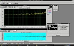
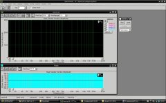
attached you will find two configuration files for SpectraLab 4.32 to be copied into the CONFIG directory of the program. Then you need to run the program and load one of the two presets using the F8 short key. Attached also is a screen hardcopy of SpectraLab 4.32. Press the RUN button in the main menu and you are done : you get the realtime high resolution plot. As explained before you get a high precision amplitude and phase graph because the measured signal is internally compared (divided) by the test signal in the FFT domain. This measurement modality is "Real Transfer Function Right divided by Left" as displayed on top of each curve window. Thus, your pink noise output signal is Line OUT and it must go back to Left Line IN. Make your own cabling. The signal coming out of the mike must enter Right Line IN. Make sure the routing and the levels are correct in the Windows Sound panel. Quite often, selecting a 100% amplitude at the Line OUT in the Windows panel overloads the Line IN inputs. Use a 30% level out for LINE OUT and adjust the LINE IN sensitivity in such a way that the bargraph stays yellow in SpectraLab 4.32.
If you are using a Laptop without LINE IN and LINE OUT jacks, use an external multichannel USB sound card like SWEEX SC016 (7.1 channel) or TRUST SC5500 (5.1 audio) or TERRATEC Aureon 5.1.
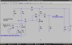
Attached you have the mike preamp schematic with a 9V battery as power supply. And the LTspiceIV simulation file.
Steph
attached you will find two configuration files for SpectraLab 4.32 to be copied into the CONFIG directory of the program. Then you need to run the program and load one of the two presets using the F8 short key. Attached also is a screen hardcopy of SpectraLab 4.32. Press the RUN button in the main menu and you are done : you get the realtime high resolution plot. As explained before you get a high precision amplitude and phase graph because the measured signal is internally compared (divided) by the test signal in the FFT domain. This measurement modality is "Real Transfer Function Right divided by Left" as displayed on top of each curve window. Thus, your pink noise output signal is Line OUT and it must go back to Left Line IN. Make your own cabling. The signal coming out of the mike must enter Right Line IN. Make sure the routing and the levels are correct in the Windows Sound panel. Quite often, selecting a 100% amplitude at the Line OUT in the Windows panel overloads the Line IN inputs. Use a 30% level out for LINE OUT and adjust the LINE IN sensitivity in such a way that the bargraph stays yellow in SpectraLab 4.32.
If you are using a Laptop without LINE IN and LINE OUT jacks, use an external multichannel USB sound card like SWEEX SC016 (7.1 channel) or TRUST SC5500 (5.1 audio) or TERRATEC Aureon 5.1.
Attached you have the mike preamp schematic with a 9V battery as power supply. And the LTspiceIV simulation file.
Steph
Attachments
Last edited:
hi Buggsson,
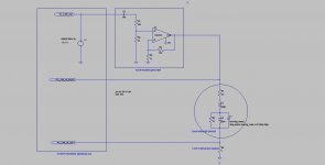
here is the SpectraLab4.32 setup for measuring the T/S parameters using the additional mass method. Note the vertical scaling, linear 0 to 3000% which means 30 ohm if you are using a 1 ohm reference resistor. Main menu ... options ... scaling ... linear. The displayed curve is always 1 ohm more than the actual Z magnitude of the speaker. You may take it out manually in the calculations, or use a more complicated circuit using a difference amplifier (sensing the voltage difference on the speaker driver terminals) feeding the PC_LINE_IN_RIGHT input.
here is the SpectraLab4.32 setup for measuring the T/S parameters using the additional mass method. Note the vertical scaling, linear 0 to 3000% which means 30 ohm if you are using a 1 ohm reference resistor. Main menu ... options ... scaling ... linear. The displayed curve is always 1 ohm more than the actual Z magnitude of the speaker. You may take it out manually in the calculations, or use a more complicated circuit using a difference amplifier (sensing the voltage difference on the speaker driver terminals) feeding the PC_LINE_IN_RIGHT input.
Attachments
Last edited:
- Status
- This old topic is closed. If you want to reopen this topic, contact a moderator using the "Report Post" button.
- Home
- Loudspeakers
- Multi-Way
- Before I start out, I need some direction