Re: split resistors?
Hi,
The 2 ohm resistor on the left changes the source impedance seen
by the CL filter and thus its Q. Q is also affected by the right side
loading of driver and resistor.
Change Q and you change phase asnd response shape.
It also makes the filter relatively uncritical of amplifier damping
factor, i.e. valve amplifier friendly.
") /sreten.
/sreten.
PeteMcK said:
On that site, Lou says for the xover 'On the tweeter side,
the split resistors are used to help with phase alignment'
Interesting, can anyone tell me how that works?
cheers,
Pete McK
Hi,
The 2 ohm resistor on the left changes the source impedance seen
by the CL filter and thus its Q. Q is also affected by the right side
loading of driver and resistor.
Change Q and you change phase asnd response shape.
It also makes the filter relatively uncritical of amplifier damping
factor, i.e. valve amplifier friendly.
/sreten.Hi Dan,
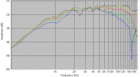
don't know if you are still reading this.... but I also got a similar 2.5KHz dip with my 27TBFC/G. Red is my measurement, cyan is yours (overlaid). Did you manage to resolve yours?
My setup
ECM8000 - uncalibrated but using a generic calibration file (which brings the top end of the 27TBFC/G in line with others' measurements)
Event EMP-1 mic preamp
Hardwired jig
El cheapo soundcard
PII/450 running Windows 98SE
Measurement conditions
Measured with SW
Gated on-axis with tweeter at 1m. - approx 3.9msec gate (128 data point resolution). Microphone / tweeter axis 1.7m from floor
Room 7.5m x 5.5m with cathedral ceilings
Tweeter flush mounted in 14.5L enclosure, centered on baffle (don't have exact dimensions handy).
Dave.
Attachments

Hello Dave,
I have resolved the 350hz dip in the XG18's response, but not the 27TBFC/G 2.5khz dip. We are both using ECM8000 microphones with generic calibration files... I wonder if the dip is caused by a miscalibrated microphone? That would explain why it showed up in both the tweeter and woofer measurements.
Did you also measure a dip in your woofers response?
Dan
I simplified my crossover, adjusted my lpad, and took some more measurements today. Results below:
On axis
15 deg off axis
30 deg off axis
The 2.5khz dip is gone 15 degrees off axis. I still have to make some minor crossover tweaks, but this project is coming close to completion.
Dan
On axis
An externally hosted image should be here but it was not working when we last tested it.
15 deg off axis
An externally hosted image should be here but it was not working when we last tested it.
30 deg off axis
An externally hosted image should be here but it was not working when we last tested it.
The 2.5khz dip is gone 15 degrees off axis. I still have to make some minor crossover tweaks, but this project is coming close to completion.
Dan
TurboFC3S said:So what was your finding for the cause of the 350hz dip?
I suspected it was the back wave of the XG18 reflecting from inside the enclosure, and radiating through the diaphram. Since my window was so short, I couldn't be shure if the dip was really at 350hz, or lower. There was a dip-peak-dip at 350hz, 750hz and 1412hz, so this made sense.
To get rid of it, I added a 7" x 5.5" x .75" piece of MDF, at an angle, between the woofer and tweeter. I figured this would increase the effective length of the enclosure, creating a semi-transmission line. I then stuffed the back half of the enclosure, and added lots of acoustic damping to the woofer chamber. Here's what it looks like.
An externally hosted image should be here but it was not working when we last tested it.
An externally hosted image should be here but it was not working when we last tested it.
The gated 1m measurements from my previous post show the dip is mostly gone. Below is a non-gated semi-nearfield measurement of only the woofer, taken from about 20cm. I figured that was far enough that the enclosure and baffle effects would not be swamped out by room reflections.
An externally hosted image should be here but it was not working when we last tested it.
The XG18 rolls off very slowly because it only has one inductor in series with it, with no impedance compensation.
Dan
Jay_WJ said:Dan,
When you obtained your original measurement without the dividing MDF piece, did you use enough acoustic damping and stuffing inside the box? Just curious.
This time around I used a little more sonic barrier... probably 20% more than before. The 1" thick piece of foam attached the MDF is new. Same amount of stuffing.
The original FRD file indicated the following:
Peaks at 219hz, 758hz, 1057hz, 1728hz
Dips at 365hz, 873hz, 1397hz
Of these, the dip-peak-dip pattern at 365hz, 758hz and 1397hz looked most suspicious. This is what I would expect to see if the back wave of the XG18 was reflecting off something 18-19 inches away, then coming back and radiating through the XG18 itself.
I thought 18-19 inches was long for an enclosure that is only 12.5" x 10.75" x 7" internally, until I realized the stuffing is doing it's job and extending the acoustic length of the box.
With the MDF piece partitioning the front half of the enclosure in two, I expect the acoustic length to be longer. I need to find a friend with a warehouse, so I can take 10ms+ gated measurements, and confirm some of what I think is going on.
Dan
- Status
- This old topic is closed. If you want to reopen this topic, contact a moderator using the "Report Post" button.
- Home
- Loudspeakers
- Multi-Way
- Need advice on crossover design for Vifa XG18 + Seas 27TBFC/G (measurements included)