Calling John *Zaph*... 5.25" midwoofer designed/built from scratch
Well hopefully John sees this because I would like to send him one for his feedback when they finally appear at my door step...
I could use some feedback here as well.
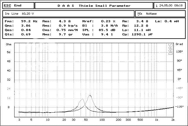
This FR is just the same cone/surround on a different lower Le, less open motor (no pole venting) in order to get a feel for the FR:
It has a stamped frame that allows slightly closer c2c spacing however that makes a home-made jig necessary for routing work instead of the handy jasper jig.
I'm looking at ~60-80W RMS in theory (which still needs bench tested) and 5.5mm of xmax.
The sensitivity and BL are a bit on the low side, however it should do nicely IB or in car. They still do quite well in small sealed if a slight 1-2 dB peak is acceptable and they do rather impressively in a number of ported alignments especially with a bit of EQ. I think I will be working with .3 cuft sealed or .4 cuft @ 50hz with 2dB of cut at 100hz, Q of 1. The extra power handling with the high temp coil makes up for this lack of sensitivity.
I'm working on finding an appropriate cast frame with venting under the spider landing for a future higher end high value unit with nice thick short paths, a phase plug and hopefully a spectra fiber (or any HSHMPE High Strength High Modulus Polyethylene Fiber) cone if I can find a manufacturer that is capable of producing them. If I can't make a cone out of pure fiber in a reasonable time frame at a fair price I will work on a wood pulp mix with this fiber in it. All units are made with 1006 steel as my standard unless a super alloy or pure (99.95%+Iron) is used.
I guess you could call this project extreme DIY. I would like to work some more with other people on future projects but between finals and the current projects I have on my plate I am completely swamped. I'm pressed for time and money to keep doing such insane projects
Well hopefully John sees this because I would like to send him one for his feedback when they finally appear at my door step...
I could use some feedback here as well.
This FR is just the same cone/surround on a different lower Le, less open motor (no pole venting) in order to get a feel for the FR:
It has a stamped frame that allows slightly closer c2c spacing however that makes a home-made jig necessary for routing work instead of the handy jasper jig.
I'm looking at ~60-80W RMS in theory (which still needs bench tested) and 5.5mm of xmax.
The sensitivity and BL are a bit on the low side, however it should do nicely IB or in car. They still do quite well in small sealed if a slight 1-2 dB peak is acceptable and they do rather impressively in a number of ported alignments especially with a bit of EQ. I think I will be working with .3 cuft sealed or .4 cuft @ 50hz with 2dB of cut at 100hz, Q of 1. The extra power handling with the high temp coil makes up for this lack of sensitivity.
I'm working on finding an appropriate cast frame with venting under the spider landing for a future higher end high value unit with nice thick short paths, a phase plug and hopefully a spectra fiber (or any HSHMPE High Strength High Modulus Polyethylene Fiber) cone if I can find a manufacturer that is capable of producing them. If I can't make a cone out of pure fiber in a reasonable time frame at a fair price I will work on a wood pulp mix with this fiber in it. All units are made with 1006 steel as my standard unless a super alloy or pure (99.95%+Iron) is used.
I guess you could call this project extreme DIY. I would like to work some more with other people on future projects but between finals and the current projects I have on my plate I am completely swamped. I'm pressed for time and money to keep doing such insane projects
Yes, I'd say that qualifies as extreme DIY. Congratulations -- it looks great!
More info please -- why did you undertake this project? What experience or background do you have? How did you choose the diaphragm material, design the dust cover, etc...? Who built the driver for you? How much did it cost? You mentioned the reduced c2c spacing -- do you envision this driver in a line array or MTM?
I have been waiting for a manufacturer to introduce a 5.5" - 6" driver optimized for open baffle use. I was even considering sending my ideas to the established manufacturers to see if they would be interested. So I would love to know how you got this driver manufactured to your specs.
Javachip said:
More info please -- why did you undertake this project? What experience or background do you have? How did you choose the diaphragm material, design the dust cover, etc...? Who built the driver for you? How much did it cost? You mentioned the reduced c2c spacing -- do you envision this driver in a line array or MTM?
I have been waiting for a manufacturer to introduce a 5.5" - 6" driver optimized for open baffle use. I was even considering sending my ideas to the established manufacturers to see if they would be interested. So I would love to know how you got this driver manufactured to your specs.
This project is only a small part of the work I've been doing for the past 2-3 years. The point of this particular 5.25" was to have a simple project that could judge the accuracy of the simulations I have been doing and to gauge the quality of the Chinese ceramic magnets and/or the quality of their magnetizing setup. For example, the BL for this unit was about 20-25% lower than calculated (which as you see turned out pretty nicely anyways). In the future, I will be getting some samples made with the following changes:
A. A larger magnet
B. The same magnet but pre-magnetized at the magnet factory.
This will help to determine how accurate the simulations are, as well as make sure that the assembled motors are able to be fully magnetized, which I have a feeling is the weak link in terms of Quality Control.
I have a deep interest in speaker design and I have some ideas on how to push forward the industry in new ways. I also have a reliable friend in China that is connected to the industry over there and can help me overcome the language barrier which is the key to getting anything done. I do have to spend some long hours working on this series of projects way into the early hours of the morning quite frequently, but the reward of seeing your project come to life is more than enough payoff.
FEMM is a powerful free tool to help design motors and I would love to involve the community in the design process. After I'm out of college for the summer, I'll have some more time to dedicate to my projects and try to put together some tutorials for using FEMM to design motors. I have to work on a few patents which will keep me a bit busy, but that's another topic.
I would like to involve the community in the design stages for upcoming projects, since the community will be better served getting drivers that more suit our needs. It should also help keep prices at an absolute minimum, since this is a group DIY project. I started out trying to commission a 6.5" OEM driver with a partner, but that didn't go very smoothly, so I'm working on it all myself. You need truly interested and motivated people working on a project; hopefully there are a few here. If you need any more motivation, I've learned more by jumping into this project head first than I have learned in my 3 years of college so far...
I don't even want to think about how much I've invested in the more esoteric projects that still have a few hiccups to conquer. As for this 5.25", I have about $2800 currently invested in direct costs for 500 units I've designed and I'm estimating about $3500-4300 before it's actually in my hands since this is a LCL cargo load.
As for my background, I first got into DIY audio as a freshman in high school and learned by browsing the forums and reading white papers as well as tinkering.
I went through the FEH (Fundamentals of Engineering for Honors) program at The Ohio State University which helped a bit and have since been learning about the business climate at the OSU Fisher College of Business and when it comes to engineering I am picking up what I can on my own as it is needed.
As for who is making it, even with my buddy in China helping me out, it has taken me over a year to find decent parts suppliers, and still there is room for improvement, so I'll hold onto that bit of info.
Since I don't have any powerful FEA tools that allow me to model the cone breakup modes, I basically have to use common sense, look for high elastic modulus cone materials with lower densities, look at the speed of sound through the material, as well as look at the specific rigidity since as a panel gets thicker, it gets more rigid. Young'sModulus/Density^2 for a factor is a good rule of thumb, but it's a bit more complicated than that since you also have to factor in geometrical stiffness of the cone profile and skin/core interactions in composites. Basically, my line of thought about this cone was to mix in some textiles into a paper pulp and make a very sturdy paper similar to paper money. I was expecting it to have a little better self damping with the textiles but we will see how the linear distortion data looks asap.
There is a relevant white paper that shows some general trends in how the breakup modes behave for different cone profiles that I would have to dig up again...
Basically the short story on how to do this for yourself is to make some good friends in China to help you out, learn to design the motor, make drawings, browse various prior toolings to see if there is anything you can use, tool anything you need to, go over everything about 10x with a fine tooth comb, keep on top of what they are doing in China, and don't forget to sample even the most minor change, because it won't be right the first, second, and likely not even the 3rd time.
I have two different projects in mind for this unit: one consists of a MTMWW with the seas27tbfc/g ;and the peerless XLS 8" discontinued unit with the 8" units acting as powered subwoofers.
I'll make a small ultra budget MTM for my apartment with one of the Dayton neo tweeters.
The other project I have in mind is a MTMMMMM... (or some variant on the theme if someone has input) floor standing unit if I can manage to get that to behave
")
I would love to make a line array and that was in mind when this was designed but I'm not quite up to that task at the moment.
I also have some 8" speakers laying around that I picked up on ebay awhile ago that were worded as B stock Genesis 501 drivers that might be fun to use that have a fairly high Q as well.
This business model is very closely related to open source movement, the important difference being that the key innovations are to be protected by patents held by the individual. This is to reward the efforts of my future employees or individual contributors to the project to give an incentive and encourage an overall fast pace of innovation in the industry.
Matt is that you or is it Dylan?
Nice work BTW, must have been a huge commitment to get those drivers made and shipped. I wish I could be an active part in what your proposing but I suspect I couldn't give it the attention it really deserves.
I'll keep a very close eye on this thread.
Nice work BTW, must have been a huge commitment to get those drivers made and shipped. I wish I could be an active part in what your proposing but I suspect I couldn't give it the attention it really deserves.
I'll keep a very close eye on this thread.
This is Dylan, Matt is busy and not devoting his all to the project sadly...
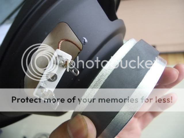
There are no short paths in this version since that would have just complicated things even further. I could have placed a copper cap on the pole but that would have necessitated me making the pole less extended to help facilitate assembly. Also I’m not a huge fan of caps when used all by themselves. This would benefit the most from a pole sleeve and/or a short path inside the ID of the top plate and/or inside the magnet. A short path disc between the magnet and top plate would also be nice if we had some magnetic energy to spare… You can plate or clad copper a part for thin shorts at a fairly high price per unit, or you can get an extrusion mould made for a high startup and a low cost per unit. I tend to opt for the later option but again the point of this unit is to release a fairly nice budget unit that can hold its own IB and hopefully has markedly low distortion in the midbass.
When a higher end 5.25” with shorts is made it will likely be using a different motor topology or just a bit of an increase on the pole diameter to 1.5” – possibly 2” or so.
I want to get a hold of John *Zaph* for the distortion measurements as well as a more accurate FR, if he is interested. The DAAS system in question is older and can’t run the harmonic distortion sweep like the newer ones can.
Edit:
Oh and any help on any projects are appreciated, they do indeed sap all of my spare time and energy. I'm sure my girlfriend wants to beat me/my computer sometimes
You can take on a pet project and work on it on and off for 2 years getting feedback I'm sure something good will come of it... The worst that could happen is that it inspires someone or a few new ideas. Or help work on the wiki segment of the webpage which is where I’d like to stick the information embedded in the threads.
There are no short paths in this version since that would have just complicated things even further. I could have placed a copper cap on the pole but that would have necessitated me making the pole less extended to help facilitate assembly. Also I’m not a huge fan of caps when used all by themselves. This would benefit the most from a pole sleeve and/or a short path inside the ID of the top plate and/or inside the magnet. A short path disc between the magnet and top plate would also be nice if we had some magnetic energy to spare… You can plate or clad copper a part for thin shorts at a fairly high price per unit, or you can get an extrusion mould made for a high startup and a low cost per unit. I tend to opt for the later option but again the point of this unit is to release a fairly nice budget unit that can hold its own IB and hopefully has markedly low distortion in the midbass.
When a higher end 5.25” with shorts is made it will likely be using a different motor topology
or just a bit of an increase on the pole diameter to 1.5” – possibly 2” or so.I want to get a hold of John *Zaph* for the distortion measurements as well as a more accurate FR, if he is interested. The DAAS system in question is older and can’t run the harmonic distortion sweep like the newer ones can.
Edit:
Oh and any help on any projects are appreciated, they do indeed sap all of my spare time and energy. I'm sure my girlfriend wants to beat me/my computer sometimes
You can take on a pet project and work on it on and off for 2 years getting feedback I'm sure something good will come of it... The worst that could happen is that it inspires someone or a few new ideas. Or help work on the wiki segment of the webpage which is where I’d like to stick the information embedded in the threads.
Nice work!
Designing a new driver like that brings to mind the KEF B-110 and the LS3-5a. It would be nice to have a new replacement driver, and/or one for clones. I realize that this is not your intent.
A clone of the 6.5" Audax driver in the Spica TC-50 would also be a good one.
The Dynaudio 8" 21W54 was an interesting driver in that it had very large mechanical Xmax, about 14 mm as I recall and a 3mm linear Xmax.
The Ascendant Audio poly 6.5 is another that I'd like to see a second source for.
Just throwing these ideas out as food for thought.
Pete B.
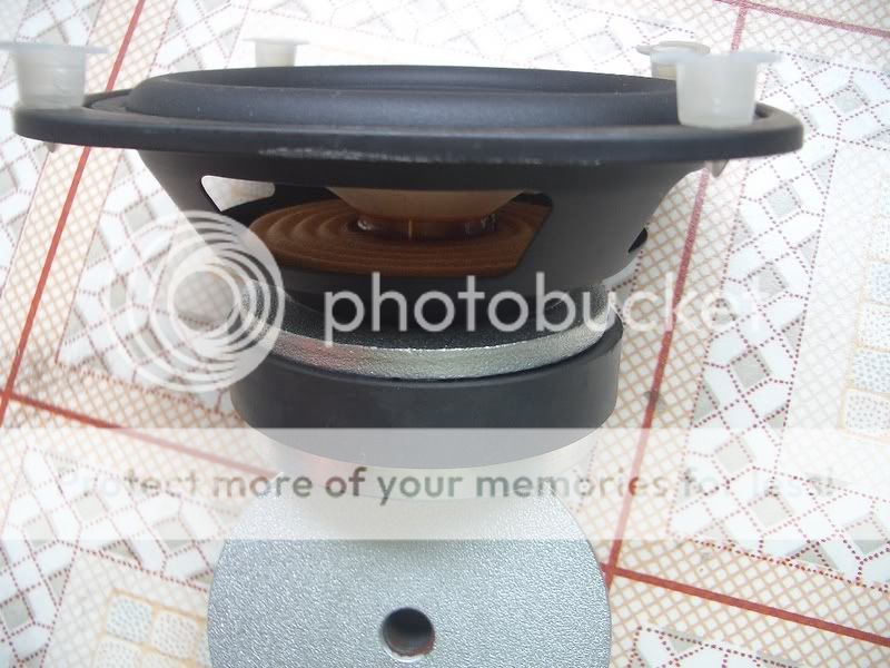
Well I have an assembled unit in front of me with a standard sorry excuse for a motor slapped on it. I was just interested in the cone quality with this sample and the midrange quality is quite impressive if I must say so myself
I would guess that it would do best crossed over under 2-2.2khz but I’m sure it can do higher than that without much in the way of compromising. I have a feeling that there could be some DIY tweaks to make this behave a little better at 2.5khz since there appears to be a bit of a larger peak there. This frame is just ever so slightly larger than the Seas MP14/RcY cast frame that I was hoping it would be a drop in replacement for.
My .02 on sound:
The midrange is more transparent than normal, and I'm hoping that my motor will have below normal distortion since that was one of my main goals. The extended pole and increased xmax should do something right? I sure hope people like it so I don't have a pile of 500 midranges cluttering up my garage.
A line array does sound nice if I can manage the time...
I would guess that it would do best crossed over under 2-2.2khz but I’m sure it can do higher than that without much in the way of compromising. I have a feeling that there could be some DIY tweaks to make this behave a little better at 2.5khz since there appears to be a bit of a larger peak there. This frame is just ever so slightly larger than the Seas MP14/RcY cast frame that I was hoping it would be a drop in replacement for
. My .02 on sound:
The midrange is more transparent than normal, and I'm hoping that my motor will have below normal distortion since that was one of my main goals. The extended pole and increased xmax should do something right? I sure hope people like it so I don't have a pile of 500 midranges cluttering up my garage.
A line array does sound nice if I can manage the time...
I should clarify a little more on that parameter I guess.
I would say that the spider comes to a hard stop at about 8-9mm and that the xsus is about 6mm. I need this verified naturally since this could be off, and its always possible that the xmag isn't perfectly centered but we can jump those hurdles if they come up in the future. I'm most interested in getting distortion data on these puppies, but I defiantly want to see what these things have on the klippel before making any more orders. Adding a mm or subtracting a mm from the voice coil former length is no big deal. If it is off by a small amount we will also get to see the exact impact on the distortion data in terms of before/after any corrections are made so no real harm done there.
Xmag when the BL was simulated vs x is 5.5mm
If you use the standard [(voice coil height)-(top plate thickness)]/2 measurement system the one way xmax is 5mm. Given that this is an extended pole. An extended pole does however change the characteristics of the BL vs. X graph in a way similar to that of a _T_ shaped Tyoke.
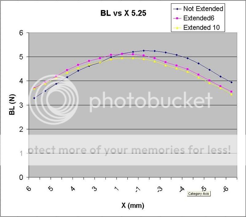
Notice how the BL is a bit lower than expected but in the end it turned out OK. I suspect that whatever caused this difference in value of the BL is also responsible for some of the 2-3dB lower sensitive we sometimes see from independent measurements vs published specs. Needless to say this investigation into Parts Quality, QC, or R/D whatever the cause may be is one of my top priorities.
A T shaped pole was out of the question for a 1" diameter voice coil due to saturation. If you ask me the greatest potential benefit to a _T_ shaped tyoke I've never seen used, and the benefit you gain is from having a very very thick short path under the T. This is easily managed as an extrusion if the T yoke is in 2 segments. One standard tyoke and one "T" piece that slides into the tyoke, or anything similar that accomplishes the same goal. Naturally you just have to keep an eye on that pole to make sure it isn't saturating on you.
One technique I would like to use in my T shaped pole projects is to have the short path be finned much like a heat sink and to have enough radial drilled holes that the cross sectional area is similar to that of a normal pole vent. Naturally all of this air will be blowing directly on this short path and directly onto the internal winds on the voice coil/voice coil former and be vented through the bottom plate or otherwise through more radial drilled holes through the top plate to further maximize airflow against the coil.
I’ll make some pretty drawings when I’m not at the library…
P.S. I have something really awesome up my sleeve but I really should to get further into patenting it first before talking about it or publishing any kind of whitepapers. Patents are a crap shot anyways so it’s best that I don’t mess that up. I hope that I can write about it by the end of summer (you never know though) but I'll just wait for the go-ahead... It is so hard to hold back :-/
I would say that the spider comes to a hard stop at about 8-9mm and that the xsus is about 6mm. I need this verified naturally since this could be off, and its always possible that the xmag isn't perfectly centered but we can jump those hurdles if they come up in the future. I'm most interested in getting distortion data on these puppies, but I defiantly want to see what these things have on the klippel before making any more orders. Adding a mm or subtracting a mm from the voice coil former length is no big deal. If it is off by a small amount we will also get to see the exact impact on the distortion data in terms of before/after any corrections are made
so no real harm done there.Xmag when the BL was simulated vs x is 5.5mm
If you use the standard [(voice coil height)-(top plate thickness)]/2 measurement system the one way xmax is 5mm. Given that this is an extended pole. An extended pole does however change the characteristics of the BL vs. X graph in a way similar to that of a _T_ shaped Tyoke.
Notice how the BL is a bit lower than expected but in the end it turned out OK. I suspect that whatever caused this difference in value of the BL is also responsible for some of the 2-3dB lower sensitive we sometimes see from independent measurements vs published specs. Needless to say this investigation into Parts Quality, QC, or R/D whatever the cause may be is one of my top priorities.
A T shaped pole was out of the question for a 1" diameter voice coil due to saturation. If you ask me the greatest potential benefit to a _T_ shaped tyoke I've never seen used, and the benefit you gain is from having a very very thick short path under the T. This is easily managed as an extrusion if the T yoke is in 2 segments. One standard tyoke and one "T" piece that slides into the tyoke, or anything similar that accomplishes the same goal. Naturally you just have to keep an eye on that pole to make sure it isn't saturating on you.
One technique I would like to use in my T shaped pole projects is to have the short path be finned much like a heat sink and to have enough radial drilled holes that the cross sectional area is similar to that of a normal pole vent. Naturally all of this air will be blowing directly on this short path and directly onto the internal winds on the voice coil/voice coil former and be vented through the bottom plate or otherwise through more radial drilled holes through the top plate to further maximize airflow against the coil.
I’ll make some pretty drawings when I’m not at the library…
P.S. I have something really awesome up my sleeve but I really should to get further into patenting it first before talking about it or publishing any kind of whitepapers. Patents are a crap shot anyways so it’s best that I don’t mess that up. I hope that I can write about it by the end of summer (you never know though) but I'll just wait for the go-ahead... It is so hard to hold back :-/
Interesting data, thanks.
Certainly the performance within the "linear" Xmax range is important, but I also find that how the driver performs beyond the linear region is as important for any driver that might be driven hard. There is sometimes rectification causing the zero crossing position to move, and the voice coil often snaps when hitting the back plate.
It is amazing to see a driver with 3mm Xmax easily do 6 even closer to 12 mm peak when driven hard. This was true of the 25F-EW in the A-25, the Advent woofer, and the Dynaudio 21W-54.
What sort of driver are you expecting to compete with?
Something like a Seas or Vifa at a lower price?
There is this driver which I believe is being upgraded with and XBL motor:
http://www.gr-research.com/drivers/m130.shtm
And the Ascendant Audio poly 6.5 has a split voice coil, kind of like XBL but with the feature in the voice coil instead of the magnetic circuit.
Very nice work, thanks for sharing your data and thoughts.
Pete B.
The Xmech for this 5.25” in its most absolute sense is 10mm at which point the former slams into back plate. The magnet height is 15mm. I'm sure I can find a larger magnet that is 18 or 20mm thick (and likely it will have to be a larger diameter) in the future if you think this is an issue worth an extra $2 or so. The surround starts to dimple up nicely in the -8mm range and if the kms induced distortion wasn't enough to make you realize its near its limit and turn it down the buckling surround surely will.
For this unit I'm hoping that people wanting to do moderately priced line arrays, I’m particularly interested in seeing this mid used in some dipoles. That would be the best way to get all of the midranges out of storage very quickly and stop the nagging I’m sure to receive as a result of about 5CBM of 5.25” midranges sitting around.
I'm hoping that this unit will be comparable with Seas Prestige Line in terms of quality but we will have to see. It reminds me a lot of the CA15RLY, the key differences being that my mms is a bit higher, I'm using a solid copper coil, I'm using a stamped frame, my 5.25" is happy IB, mine is 1/3-1/4th the cost (based off madisound pricing as of today). While my paper cone is rather unique, I have a hunch theirs is better behaved on the top end (mine is un-treated, non sticky). I am using an extended pole and I'm not sure what they are using. I know that some of their excel units do use a T shaped pole but there is no mention about the prestige line...
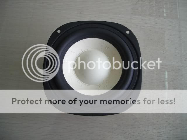
That GR research looks nice, it seems like it should be on zaph's page too... Curvilinear cones sure are curious in terms of what they do to flatten out the FR and those cute little "phase plug like" dust caps also contribute nicely to the top end rolloff characteristics.
My true conical cone with a wider, taller dust cap makes the rolloff characteristic a little nastier since the break is more obvious. There is a good side to it though; I am hoping that the CSD plot will be a little cleaner overall due to the added geometrical stiffness.
I am expecting the areas in red to be the most prone to resonance. I will play with putting a bit of goo there or possibly some reinforcing strips to see what happens to the FR as a result of the modification. The tip of the dustcap is likely responsible for that higher frequency mode, and the rim of the dust cap is likely responsible for that slight ripple at 2.5khz.
I can't find any cast frame 5.25" units with windows under the spider landing at the moment or I would have used it since that would have been a more noticeable improvement... I'll look more later though. I'm thinking that a reasonable quality stamped frame is of very comparable quality to your average cast frame. As far as I can tell, the biggest difference is simply the % of open space for the rear wave... There are other obvious benefits to a cast frame but they do cost a few times as much and this project’s objective is set to maximize value.
This sure is fun!
I’m sure at the least it will make for an interesting line on a resume, although I feel confidant that I can take this somewhere. It would be great to be doing what I enjoy the most on a continuous basis.
For this unit I'm hoping that people wanting to do moderately priced line arrays, I’m particularly interested in seeing this mid used in some dipoles. That would be the best way to get all of the midranges out of storage very quickly and stop the nagging I’m sure to receive as a result of about 5CBM of 5.25” midranges sitting around.
I'm hoping that this unit will be comparable with Seas Prestige Line in terms of quality but we will have to see. It reminds me a lot of the CA15RLY, the key differences being that my mms is a bit higher, I'm using a solid copper coil, I'm using a stamped frame, my 5.25" is happy IB, mine is 1/3-1/4th the cost (based off madisound pricing as of today). While my paper cone is rather unique, I have a hunch theirs is better behaved on the top end (mine is un-treated, non sticky). I am using an extended pole and I'm not sure what they are using. I know that some of their excel units do use a T shaped pole but there is no mention about the prestige line...
That GR research looks nice, it seems like it should be on zaph's page too... Curvilinear cones sure are curious in terms of what they do to flatten out the FR and those cute little "phase plug like" dust caps also contribute nicely to the top end rolloff characteristics.
My true conical cone with a wider, taller dust cap makes the rolloff characteristic a little nastier since the break is more obvious. There is a good side to it though; I am hoping that the CSD plot will be a little cleaner overall due to the added geometrical stiffness.
I am expecting the areas in red to be the most prone to resonance. I will play with putting a bit of goo there or possibly some reinforcing strips to see what happens to the FR as a result of the modification. The tip of the dustcap is likely responsible for that higher frequency mode, and the rim of the dust cap is likely responsible for that slight ripple at 2.5khz.
I can't find any cast frame 5.25" units with windows under the spider landing at the moment or I would have used it since that would have been a more noticeable improvement... I'll look more later though. I'm thinking that a reasonable quality stamped frame is of very comparable quality to your average cast frame. As far as I can tell, the biggest difference is simply the % of open space for the rear wave... There are other obvious benefits to a cast frame but they do cost a few times as much and this project’s objective is set to maximize value.
This sure is fun!
I’m sure at the least it will make for an interesting line on a resume, although I feel confidant that I can take this somewhere. It would be great to be doing what I enjoy the most on a continuous basis.
Greets from Berea
Dylan,
Your speculation about the resonant areas of the dustcap may be on the mark. There is another thread here about the use of Enabl patterns to release the stored energy and decrease resonance spikes.
http://www.diyaudio.com/forums/showthread.php?s=&threadid=100399
I wish you all the benefits of your efforts. I look forward to just how "open" you can get a frame. They'll be fun to work with.
Re: Greets from Berea
What a thread... I'll have to read all the associated literature more carefully and send him a PM.
Thanks for the kind words and a go ahead for an impending group buy.
There is no phase plug planned on this budget unit since I have a feeling it would necessitate some more major changes on the cone itself.
I do have a higher end offering (6.5") coming down the pipe (although slowly). I actually started that project a long time prior to this 5.25" unit but it is exceedingly more complicated and pitted with headache after headache.
The voice coil for that high end 6.5" will be 2" in diameter which forces me to give up more sd than I would like on a tiny 5.25". I've also never seen a phase plug that large on a relatively small cone so there is no prescient for how it would behave, if anyone has some info on phase plug design I would like it. I am playing with some other ideas but I have to look them over carefully. I guess this is material for a different thread though.
Ed LaFontaine said:Dylan,
Your speculation about the resonant areas of the dustcap may be on the mark. There is another thread here about the use of Enabl patterns to release the stored energy and decrease resonance spikes.
http://www.diyaudio.com/forums/showthread.php?s=&threadid=100399
I wish you all the benefits of your efforts. I look forward to just how "open" you can get a frame. They'll be fun to work with.
What a thread... I'll have to read all the associated literature more carefully and send him a PM.
BWRX said:Hi Dylan. Very nice work. Hopefully the drivers sound as good as they look. Have you thought about removing the dust cap and experimenting with phase plugs?
If/when you do decide that you want to sell these please start a new thread about them in the group buys forum.
Thanks for the kind words and a go ahead for an impending group buy.
There is no phase plug planned on this budget unit since I have a feeling it would necessitate some more major changes on the cone itself.
I do have a higher end offering (6.5") coming down the pipe (although slowly). I actually started that project a long time prior to this 5.25" unit but it is exceedingly more complicated and pitted with headache after headache.
The voice coil for that high end 6.5" will be 2" in diameter which forces me to give up more sd than I would like on a tiny 5.25". I've also never seen a phase plug that large on a relatively small cone so there is no prescient for how it would behave, if anyone has some info on phase plug design I would like it. I am playing with some other ideas but I have to look them over carefully. I guess this is material for a different thread though.
PB2 said:Interesting data, thanks.
Certainly the performance within the "linear" Xmax range is important, but I also find that how the driver performs beyond the linear region is as important for any driver that might be driven hard. There is sometimes rectification causing the zero crossing position to move, and the voice coil often snaps when hitting the back plate.
It is amazing to see a driver with 3mm Xmax easily do 6 even closer to 12 mm peak when driven hard. This was true of the 25F-EW in the A-25, the Advent woofer, and the Dynaudio 21W-54.
What sort of driver are you expecting to compete with?
Something like a Seas or Vifa at a lower price?
There is this driver which I believe is being upgraded with and XBL motor:
http://www.gr-research.com/drivers/m130.shtm
And the Ascendant Audio poly 6.5 has a split voice coil, kind of like XBL but with the feature in the voice coil instead of the magnetic circuit.
Very nice work, thanks for sharing your data and thoughts.
Pete B.
I was thinking of this driver not the 5.25 inch with regard to the XBL motor, don't want to start any rumors:
http://www.gr-research.com/drivers/m165x.shtm
Pete B.
- Status
- This old topic is closed. If you want to reopen this topic, contact a moderator using the "Report Post" button.
- Home
- Loudspeakers
- Multi-Way
- Calling John *Zaph*... 5.25" midwoofer designed/built from scratch