I'm running out of time to complete a birthday present, so my research time is limited...
I'm after an active eq design that contains two notch filters. One is for a broad peak, and the other a narrow peak for use with the FR125S drivers.
Eq filters will be in same enclosure as power amp:
Source with vol. control -> [active eq -> power amp] -> FR125S fullrange drivers
I know next to nothing about active ciruits, but so far I figure a buffer stage followed by two notches. The notch filter calcs on LR's site have me scratching my head
V
Don't worry V, it's a doddle...
Look at the first of the three circuits shown on LR's page: the 5.11K resistor forms a potential divider with the R-C-L. The problem is that the 2.5H inductor shown is going to be a well-wound monster! The second two circuits on LR's page show the same circuit but the L is replaced with an op-amp based active inductor (the R appears to vary but additional series-R is present in the gyrator which brings it back to 1.5Kohms).
So, start by determining the centre frequency of the notch, shown as fo in the diagram, by inspecting the peak in your frequency response plot.
Next, determine the required Q of the notch, again by looking at your peak:
Q = (notch centre frequency, fo) / (width of notch 3dB down from the peak, shown as delta f).
Referring to the pseudo-schematic in the top left corner of SL’s main pic, select a value for R1. Convert your frequency peak from dB into real numbers (ie 6dB = 0.5, 12dB=0.25, etc) and calculate the depth of the notch from R3/(R3+R1) to correspond.
You can now calculate L and C as shown in the bottom right hand corner of SL’s main pic.
To replace L with an active inductor, click on INDUCTR1.GIF or INDUCTR2.GIF and use the formula shown for calculating L (I've used the first circuit with good success). The pics also allow you to calculate Rs, the effective series resistance, which you subtract from the R in the R-L-C.
The notch filter should really be followed by a buffer to guarantee that the load (R2) does not affect the circuit operation.
I'm tired and drunk so errors and omissions can only be expected!
I hope this helps,
David.
Rane PE 17? Maybe not good enough in the sound department, but as I can pick up one for me for about $200Aus (which is probably less than a 2.5H inductor) it's going to do for my subwoofer PEQ. And, you'd need 2 of them...
You may need something a bit better (or should I say, less) sounding for the FR125...
You may need something a bit better (or should I say, less) sounding for the FR125...
Enormously. Thanks.daatkins said:I hope this helps,
David.
I've attached a spreadsheet following your comments. It's for a 6.5kHz peak with Q of 6.5 that needs 6db notch. Does it look roughly correct?
Rename file to .xls
Edit:
Also, am I correct in thinking that a single package quad opamp is all that's needed for the two buffers and two notch/gyrator circuits per driver?
V
Attachments
Ohhh, my head...
My drunken ramblings must have confused you slightly as an error has crept into your calculations: the active inductor you've calculated is for 81.3mH whereas it should be 813mH. Other than that, I agree with:
R1 = 5110R
R3 = 5100R
C = 737pF
L = 0.813H
... and using standard values for the active inductor, I get:
C = 1uF
R1 = 1K
R2 = 810R
so R3 reduces to 3.3K
I'll do a simulation of the circuit when I get home just to triple check.
Another useful check is to verify the circuit (when it's built) using Speaker Workshop. Connect the soundcard output to the filter input and the filter output to the soundcard input and set the levels low. Simply click Resource/New/Driver then Measure/Frequency Resp/Nearfield and the frequency response of the filter is shown on the screen. Marvellous!
A quad op-amp would be fine a something like this - the only problem might be cramming all the components around the package. For this reason, I tend to prefer two duals instead one quad.
Nice one,
David.
My drunken ramblings must have confused you slightly as an error has crept into your calculations: the active inductor you've calculated is for 81.3mH whereas it should be 813mH. Other than that, I agree with:
R1 = 5110R
R3 = 5100R
C = 737pF
L = 0.813H
... and using standard values for the active inductor, I get:
C = 1uF
R1 = 1K
R2 = 810R
so R3 reduces to 3.3K
I'll do a simulation of the circuit when I get home just to triple check.
Another useful check is to verify the circuit (when it's built) using Speaker Workshop. Connect the soundcard output to the filter input and the filter output to the soundcard input and set the levels low. Simply click Resource/New/Driver then Measure/Frequency Resp/Nearfield and the frequency response of the filter is shown on the screen. Marvellous!
a single package quad opamp is all that's needed
A quad op-amp would be fine a something like this - the only problem might be cramming all the components around the package. For this reason, I tend to prefer two duals instead one quad.
Nice one,
David.
Thanks David.
My mis-calculation of L was a result of not paying attention to the zeros after the decimal point. Your explanation was perfect!
Can I adjust R1, R2 and C in the active inductor to any ratio I like (based on what's available in my parts bin), or is there some method to this? I would think that keeping C low so that I can use a poly cap would be good, but that's about it.
How should R1 in the notch be calculated?
Finally, can you recommend any free and simple to use software for trying out these circuits.
I've used ARTA in the past to verify an active circuit (the ASP for the Orions). It's even better than SW")
Hope the hangover has subsided
V
My mis-calculation of L was a result of not paying attention to the zeros after the decimal point. Your explanation was perfect!
Can I adjust R1, R2 and C in the active inductor to any ratio I like (based on what's available in my parts bin), or is there some method to this? I would think that keeping C low so that I can use a poly cap would be good, but that's about it.
How should R1 in the notch be calculated?
Finally, can you recommend any free and simple to use software for trying out these circuits.
I've used ARTA in the past to verify an active circuit (the ASP for the Orions). It's even better than SW
Hope the hangover has subsided
V
Vikash said:I'm running out of time to complete a birthday present, so my research time is limited...
I'm after an active eq design that contains two notch filters. One is for a broad peak, and the other a narrow peak for use with the FR125S drivers.
Eq filters will be in same enclosure as power amp:
Source with vol. control -> [active eq -> power amp] -> FR125S fullrange drivers
I know next to nothing about active ciruits, but so far I figure a buffer stage followed by two notches. The notch filter calcs on LR's site have me scratching my head
V
Sorry to barge in, like this. But maybe I have some helpful information, for you, if you run some form of Windows:
I have used the free FilterPro software, downloadable from http://www.ti.com , and think it might be pretty good for more-or-less automatically designing an opamp-based filter for what you are wanting to do. It supports quite a few filter topologies that you can select from, and draws a schematic of each circuit it designs per your specs, and also plots the amplitude and phase response of the resulting filter circuit.
And the free LTSpice software, downloadable from http://ltspice.linear.com/software/swcadiii.exe , is an excellent and extremely easy-to-use circuit simulator, and could be very useful if more details of the filter circuit's operation, or the results of tweaks, or of using different components' models, are desired.
If you need more Spice models, take a look at: http://homepages.which.net/~paul.hills/Circuits/Spice/ModelIndex.html
While I'm at it: There is also a truly-great support/discussion group, specifically for LTSPice, at http://tech.groups.yahoo.com/group/LTspice
Good luck.
- Tom Gootee
http://www.fullnet.com/~tomg/index.html
-
Hi Vikash,
Yes, although (R1 + R2) must be less than, or equal to, R3 so that can limit the range of values that are suitable.
When the frequency is at f=1/((2*pi*L*C)^0.5), the reactance of the inductor and the reactance of the capacitor are equal in magnitude but opposite in phase so the two impedances cancel each other out, leaving just R1 and R3 (in the passive circuit or R1 and Rs when the active inductor is used). To put it another way, it's the ratio of R1 and R3 that sets the depth of the notch.
I pick a value R1 and use that as a basis to calculate the rest of the components. You have a lot of freedom when selecting R1 and R3 but I'd stay away from anything too high (greater than 100K, say).
Like Tom said! I've used LTSpice with great success.
I've also simulated the circuit but it's not 100% correct: the center frequency is spot on at 6.5KHz, the notch depth is exactly 6dB but the Q seems to be a little lower than it should (delta f is 1.4KHz), and I'm at a loss to explain why... The result is exactly the same whether I use the active inductor or passive. I used Multisim so please report back with the results of your simulation and we can compare notes!
So when do we get to see to photos of this new creation?
Nice one,
David.
Can I adjust R1, R2 and C in the active inductor to any ratio I like
Yes, although (R1 + R2) must be less than, or equal to, R3 so that can limit the range of values that are suitable.
How should R1 in the notch be calculated?
When the frequency is at f=1/((2*pi*L*C)^0.5), the reactance of the inductor and the reactance of the capacitor are equal in magnitude but opposite in phase so the two impedances cancel each other out, leaving just R1 and R3 (in the passive circuit or R1 and Rs when the active inductor is used). To put it another way, it's the ratio of R1 and R3 that sets the depth of the notch.
I pick a value R1 and use that as a basis to calculate the rest of the components. You have a lot of freedom when selecting R1 and R3 but I'd stay away from anything too high (greater than 100K, say).
can you recommend any free and simple to use software
Like Tom said! I've used LTSpice with great success.
I've also simulated the circuit but it's not 100% correct: the center frequency is spot on at 6.5KHz, the notch depth is exactly 6dB but the Q seems to be a little lower than it should (delta f is 1.4KHz), and I'm at a loss to explain why... The result is exactly the same whether I use the active inductor or passive. I used Multisim so please report back with the results of your simulation and we can compare notes!
So when do we get to see to photos of this new creation?
Nice one,
David.
Bizaare. I've just designed my first active eq filter without using any active components
The notch calculation seems to have worked a treat. Let me know if the result matches yours.
Any ideas on how to export the data to .frd format or similar so that I can apply it to measured FR using Speaker Workshop for example?
Thanks
V
The notch calculation seems to have worked a treat. Let me know if the result matches yours.
Any ideas on how to export the data to .frd format or similar so that I can apply it to measured FR using Speaker Workshop for example?
Thanks
V
Attachments
Vikash,
You're part of the way there. However, note the value of the inductor. It's very large.
Substituting the L with an active inductor is the fun part.
I prefer LspCAD for simulating notch filter circuits. You tell it what notch depth, frequency, and Q you need and it'll generate a circuit and also give you the option to save the response in an ascii (frd) format.
Cheers,
Davey.
This is the complete filter design. Any feedback appreciated.
I'm quite impressed with LTSpice. LspCAD seems just the ticket although it kept crashing when I demoed it in the past, and looking at the current costs, I think I'm better off with the longer but free methods!
Now how do I go about converting this into a PCB design? I don't see any point in doing just a half job!
V
Attachments
Vikash,
a related way of doing this is with a graphic equaliser type of circuit see this thread and scroll down to posts 10 and 11:
http://www.diyaudio.com/forums/showthread.php?threadid=88123
a related way of doing this is with a graphic equaliser type of circuit see this thread and scroll down to posts 10 and 11:
http://www.diyaudio.com/forums/showthread.php?threadid=88123
Vikash said:
I'm after an active eq design that contains two notch filters. One is for a broad peak, and the other a narrow peak for use with the FR125S drivers.
Eq filters will be in same enclosure as power amp:
Source with vol. control -> [active eq -> power amp] -> FR125S fullrange drivers
V
Hi,
FWIW if you are also building the power amplifier it should be
possible to use the power amplifier as the active element, i.e.
manipulate its input network and feedback network.
If the two frequencies are separate enough not to interact
too much they can both implemented in the same circuit.
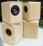
/sreten.Some nice looking boxes there, V.
The results of your first simulation appear to match mine perfectly i.e. your Q is too low as well! Your original post said the width of the notch at 3dB is required to be 1Khz (for a Q of 6.5) but it looks larger in the simulation; approching 2KHz, I'd guess.
Can anyone here explain the discrepency?
Just a couple of points...
I'm not sure if you intend to have R9 in the circuit or not. It's not really doing any harm but is adding constant attenuation across all frequencies.
When designing the PCB, you may want to add a spare parallel capacitor to positions C1, C2, C4 and, erm, "700pF" to allow you to do somw fine tuning of the values.
Well, do you have any PCB software? Having typed that, something this simple could probably by hand drawn on the copper board fairly easily.
Nice one,
David.
The results of your first simulation appear to match mine perfectly i.e. your Q is too low as well! Your original post said the width of the notch at 3dB is required to be 1Khz (for a Q of 6.5) but it looks larger in the simulation; approching 2KHz, I'd guess.
Can anyone here explain the discrepency?
This is the complete filter design. Any feedback appreciated.
Just a couple of points...
I'm not sure if you intend to have R9 in the circuit or not. It's not really doing any harm but is adding constant attenuation across all frequencies.
When designing the PCB, you may want to add a spare parallel capacitor to positions C1, C2, C4 and, erm, "700pF" to allow you to do somw fine tuning of the values.
Now how do I go about converting this into a PCB design?
Well, do you have any PCB software? Having typed that, something this simple could probably by hand drawn on the copper board fairly easily.
Nice one,
David.
Again, I'm a newbie with PCB design so no software or experience to speak of. I'm downloading Eagle now. Not sure what the process is exactly, but I'll probably go the laser printer and home etch route.
consort_ee_um, I was looking for that schematic earlier. Thanks. I want to keep it simple to begin with, but might add an eq circuit to fill in the trough depending on the FR measurements I've yet to take.
V
consort_ee_um, I was looking for that schematic earlier. Thanks. I want to keep it simple to begin with, but might add an eq circuit to fill in the trough depending on the FR measurements I've yet to take.
V
In preperation for designing the eq filter PCB, I've attempted to first do a simple regulated PSU to power it. Again, any feedback (of my first ever PCB design!) is appreciated.
Eagle has a less intuitive UI- than Speaker Workshop even! Getting there slowly though...
V
Eagle has a less intuitive UI- than Speaker Workshop even!
Getting there slowly though... V
Attachments
If you are going to the trouble of making PCBs for all of this, would it not be a good idea to include a shelving network for bafflestep compensation? And possibly also add in a highpass to cut out the frequencies the driver isnt producing, thus increasing power handling, and also giving flexibility with using a sub.
Just a thought.
Matt
Edit - the PCB looks fine, as a tip though, its useful to make the pads as large as they can be whilst being functional, this makes soldering and drilling easier. Also make the tracks as wide as they can be, especially the ones handling power.
Just a thought.
Matt
Edit - the PCB looks fine, as a tip though, its useful to make the pads as large as they can be whilst being functional, this makes soldering and drilling easier. Also make the tracks as wide as they can be, especially the ones handling power.
Hi there Vikash,
Your PCB looks great for a first effort! My only suggestion would be to thicken-up all the tracks - not to increase current capacity, which isn't really needed for this circuit, but in case some of the track etches away. I've made plenty of PCBs using the blue Press 'n Peel sheets and I don't go below 0.030" for track thickness for this reason.
I know you said you wanted to use parts from the good ole' spares box, but I believe it's worth ordering a few surface mount parts (100nF decouplers, 1K, 10K resistors etc) for any future PCBs you might make, simply because it reduces the amount of drilling required. Decent drills in the 0.6mm to 1mm range cost a couple of quid each so you only need to snap one to make the investment worthwhile.
Nice one,
David.
- Status
- This old topic is closed. If you want to reopen this topic, contact a moderator using the "Report Post" button.
- Home
- Loudspeakers
- Multi-Way
- Active Notch Filter design needed