rcavictim,
Someday you will have to share with us just what caused your choice of moniker.
I am afraid I have to perform open mind set surgery on you.
I am not advocating any sort of damping process.
Nothing I do in the EnABL realm has anything to do with damping of any sort.
I realize it is painful to let go of the devil you know, but to understand what I am up to you really must leap into the vast empty spaces without the Wings of Damping attached to your mind.
When you damp an active surface you store and either never release the energy and transform it to another form, or you re-release it over time. No other choices are allowed on this dirt ball.
Unless you have a perfect containment as a damping scheme, you will suffer corruptions to the energy left, after damping. Plus there is this critical Q of just how much is just enough?
Rather than fight this battle of mass and space and taste I just fling the energy off the precipice edge, into the air, without damping of any kind, but, I fling all of it off the edge at the same time and at the same angle of incidence and into the same longitudinal pressure wave.
The EnABL pattern is a trap for unsuspecting energy. Note, you can stack energy and stacked energy does present only the option of further stacking to any additional energy attempting to occupy the same location. As the energy passes through the pattern it stacks within the "passes" and since it is in a three vector wave guide, that extra stacking will cause quite a lot of the energy stacked therein to just express into the attached longitudinal pressure wave being built anyway.
The distance to the "edge" from the pattern is so short that energy that gets scared and refuses to jump willingly is collected by the wave of energy flowing into the longitudinal wave and also jumps off the surface into that third vector. Since the energy density is so great in this trap area it acts like a super fluid with a high surface tension and very little energy remains in the boundary layer, past the EnABL pattern.
This remanent energy does re-radiate back through the pattern in the boundary layer, to travel back across that boundary layer, only to find yet another trap. The two laser interferometry looks I have had at this activity indicate that this energy that does remain is on the order of 80 dB down from the original signal, for non systemic resonances.
I do not know if the EnABL pattern can be used to further a damping scheme. I find that I am uninterested actually, mostly because I am still gasping for mental breath from having unearthed all of this thought process, from the mental dust bin I consigned it to 5 years ago or so.
It is good that you are stretching your mind to encompass an entirely new approach to energy management in our neat interest realm.
If you want to pursue mass damping instead so be it, but really, when done properly, this scheme works so well that there is nothing left worth damping.
Bud
Hi again Bob,
I find that, indeed, I am not uninterested in mass damping schemes.
The thought decanted into my awareness is primarily for an Open Baffle speaker. Imagine a rectangular frame with openings to allow pouring of sand into this rectangle once it is skinned. Skin with constrained layers of mahogany single ply with viscous glue as the layer constraint and each laer growing in size and changing from a rectangle into a musical instrument style of French Curve terminus edges.
Your spaces with lead balls are distributed through out the ply layers to ensnare energy pulses that excurt beyond a single ply skin and the final ply has the EnABL pattern applied for final surface control.
The back side would also be constrained layer skins but would devolve in size to provide a shaped back bezel with a longer path length than the front side, to encourage a back angled phase skirt for the null zone.
All drivers would be mounted to MDF rings, held in place with thin dowels and supported by the sand and outer ply skins.
In my brain, the various layers reduce the systemic resonances layer by layer and the curlicued final shape provides a non symmetrical path length, further limiting the creation of standing waves.
Ed,
I meant to say that I take a finished cabinet, apply the pattern with flat clear acrylic paint and then cover only the pattern with the conformal coating. That the conformal coating material, not the pattern paint, was the mad to bubble material mentioned, with out excuse nor seeming remorse for it's criminal behavior.
Bud
That trip to the Patent Office was worth it (search for # 5304746).
Having read through it the first time I've found most of my questions answered. It is heady stuff in that what is being offered is outside of the box I've been in.
I had to put down the urge to ask "How could that happen?" several times in order to push through it. I'm gonna step outside and read it again before posing more questions.
Regarding my misallocation of credit due Bud, sometimes Mongo just kicks poetry right off the porch.
Hi All,
Go and take a quick look at the frequency plots at the tail end of the white paper on EnABL Specifically the initial curve trace of untreated Vs treated cone tweeter.
http://www.positive-feedback.com/Issue21/standingwaves.htm
That sort of "smoothing" up in the harsh top end of cone drivers is very typical of treated cones. So you may be able to have less than perfect cone activity here and not suffer from it. I suspect that a Mamboni process also applied to the cone driver bottom back cone skirt will help smooth things out, as these frequencies, at the top of a drivers range are where the worst sounding of the offending standing waves are created.
Bud
Hi Ed,
I know exactly what you mean. In the usual best pea patch manner, I am quite self absorbed when on one of these rampages. There are more we haven't discussed yet. It is only when I can catch my breath and stand back, that the fear sets in.
Questions like "How could this be" are usually for later. "What have I done" and "are they are gonna commit me over this one" are early candidates. Trust me, the EnABL thing is not the most unbelievable activity I have going on here. It is the only one I was ever foolish enough to patent. The rest of the non mainstream plants from this here pea patch just twist your head around and the only sound that will come out of your mouth is vooooodooooooo.
I am just getting around to enjoying the thoughts Bob offered a little earlier. The one about using pre-splatted cow barn padding to make pointy ended, yellow colored flower petal, Open Baffle, speaker boards from, does appeal, once you get over the mental pictures and olfactory expectations. That, Empirical Whip and Black and Blacker are very resonant here in the Pea Patch of the mad, out on the upper left crust of the united snakes....
Thomas tells me privately that he is working the problem of application. Spending money like grandpaw at christmas and having great fun.
Bud
Hi all,
Not to belabor the point ...oh no not at all.... and here we go again...
The EnABLE cones, from my experience, all have dispersion angles that are controlled by the cone angle of incidence. If the driver has a dome, and the dome is treated, you can be certain of getting significantly smoothed high frequencies and they will be controlled in dispersion by the cone walls.
Not kidding here, but, I have almost no experience with open center drivers. Although the highs will be just as smooth, I am not dead certain that the dispersion will be just as it is when the dome is present.
A center horn can also be integrated much more smoothly with a treated cone, but , you will have to ditch the screen, and you want to, trust me.
Bud
Chris, Did the PM go through, I am never sure I have the procedures quite straight.
As for the color of the cone, I do not know. Just the shiny surface and semi transparent nature of the cone, you can see the Mamboni triangles through the whizzer cone, are familiar.
Phase plugs and other post emitter surfaces all seem to benefit. I have no experience with phase plugs per se but I can see what I would do for many of the ones I have looked at.
The main thing to keep in mind is that this is a three vector pattern and seems to need to be placed just before any major deviation in surface is encountered. So, if the phase plug is an oblate shape, just before its surface becomes tangential to the emitting longitudinal compression wave front, is the most useful place to put the pattern. At the start and actual finish, if there is a distinct one at all, are also places to treat. These will be very small in benefit compared to the one at the tangential circumference.
Once you get involved with this pattern you do tend to treat all surfaces, just to learn the benefits, and one of the benefits is a reeducation of your correlator. Well, "benefits" I suppose, as you will become a bit short on tolerance for drivers that are not as well behaved as the EnABL'ed units are. Something of a pain some times.
Dave,
How should I go about this collection process? Just find and note all of the post numbers in the various threads, copy them to an email along with the initial text you mentioned? Or do I need to copy and reformat the actual posts themselves and send that plus the beginning one?
Bud
Hi R Jamm,
I will finish building up the 2nd test speaker tomorrow. On this 2nd speaker I have reduced the height by 4 inch's from 28 inch to 24 inch. The reason for this is that with the 28 inch speaker I notice a "richer" sound when I stand up and my ear is above the baffle and speaker frame - so I am trying to get that same richness when I am sitting. I thought of reducing the height even more but was afraid I would lose to much bass response. I'll know tomorrow when I finish building unit number 2.
I must say that the Pioneer 10 inch mid-woofer doesn't seem to take much to break in - about a day seems to it! My Fostex 167's took a solid week - heck they were so tight when they were new that I had to kick up the amp to around 90db's just to get 'em moving and then back it off to mid level and just let 'em cook. The Pioneer fired up right away and seemed pretty good from the get-go!
I am still amazed by the openness of the sound these units produce! Taking the speaker box pretty much out of the usual scheme of being a "box" that "aims" the direction of the traditional speaker is nixed and these things - they sound similar to OB designs - very open sound and very smooth.
I'm looking around for a different tweeter than my Heils - just to see what is out there in today's world. My current thinking is to use a tweeter that is good from say 3 khz up to above 18 Khz and mount it in a similar configuration as the Pioneer (reduced in scale of course) and flip it upside down so the magnet of the tweeter would be back to back with the magnet of the Pioneer. I'll work up a sketch and put in a later post to show what I'm thinking of.
I'm also thinking that the baffle the Pioneer sits atop of is a bit to wide because of the 14 inch SonoTube I'm using. So I'm considering putting a dome shaped baffle on one of the test units and doing some EnABL patterns to see how that helps smooth things out.
One thing that I'm still very sure of - for the cost and ease of construction this is one heck of a speaker!
I FINALLY got my Micro Gloss delivered at the local hobby shop so now I can start doing some of BudP's EnABL patterns!!
The stencil experiments just did not work out well at all - although I still want to try a couple of things. Right now it looks like the way I'll go with applying EnABL is to use Speedball Calligraphy Pens - sizes A0 thru A5 (square, flat tip on the A series) and the Polly S acrylic paint. I'll print out a pattern on regular paper and trim it down to a size that I can tape to the speaker near the area to be treated and use it as a guide. Then it's a careful touch with the correct sized Speedball tip and whack-o - my speaker cones have been EnABLed!
BTW - the problem with the silkscreen stencil was that the Polly S paint is so thin that it would creep underneath the edge of the screen and blot out around the edge of the pattern. It could make for a rather interesting "ink blot" test (perhaps something I should be considering ) but not a very good application of BudP's EnABL pattern.
I noticed on another thread that there is some discussion of BudP getting his own EnABL thread going here sometime soon. Congratulations Bud!
My suggestion is to put an EnABL pattern all the way around the edges of it in order to keep things smooth and dump off all distortions and distractions. But then I guess that most of the stuff I'd post would wind up in the bit bucket! :bs:
Attached is a photo of test tube #2! I will report on the findings!
I will finish building up the 2nd test speaker tomorrow. On this 2nd speaker I have reduced the height by 4 inch's from 28 inch to 24 inch. The reason for this is that with the 28 inch speaker I notice a "richer" sound when I stand up and my ear is above the baffle and speaker frame - so I am trying to get that same richness when I am sitting. I thought of reducing the height even more but was afraid I would lose to much bass response. I'll know tomorrow when I finish building unit number 2.
I must say that the Pioneer 10 inch mid-woofer doesn't seem to take much to break in - about a day seems to it! My Fostex 167's took a solid week - heck they were so tight when they were new that I had to kick up the amp to around 90db's just to get 'em moving and then back it off to mid level and just let 'em cook. The Pioneer fired up right away and seemed pretty good from the get-go!
I am still amazed by the openness of the sound these units produce! Taking the speaker box pretty much out of the usual scheme of being a "box" that "aims" the direction of the traditional speaker is nixed and these things - they sound similar to OB designs - very open sound and very smooth.
I'm looking around for a different tweeter than my Heils - just to see what is out there in today's world. My current thinking is to use a tweeter that is good from say 3 khz up to above 18 Khz and mount it in a similar configuration as the Pioneer (reduced in scale of course) and flip it upside down so the magnet of the tweeter would be back to back with the magnet of the Pioneer. I'll work up a sketch and put in a later post to show what I'm thinking of.
I'm also thinking that the baffle the Pioneer sits atop of is a bit to wide because of the 14 inch SonoTube I'm using. So I'm considering putting a dome shaped baffle on one of the test units and doing some EnABL patterns to see how that helps smooth things out.
One thing that I'm still very sure of - for the cost and ease of construction this is one heck of a speaker!
I FINALLY got my Micro Gloss delivered at the local hobby shop so now I can start doing some of BudP's EnABL patterns!!
The stencil experiments just did not work out well at all - although I still want to try a couple of things. Right now it looks like the way I'll go with applying EnABL is to use Speedball Calligraphy Pens - sizes A0 thru A5 (square, flat tip on the A series) and the Polly S acrylic paint. I'll print out a pattern on regular paper and trim it down to a size that I can tape to the speaker near the area to be treated and use it as a guide. Then it's a careful touch with the correct sized Speedball tip and whack-o - my speaker cones have been EnABLed!
BTW - the problem with the silkscreen stencil was that the Polly S paint is so thin that it would creep underneath the edge of the screen and blot out around the edge of the pattern. It could make for a rather interesting "ink blot" test (perhaps something I should be considering
) but not a very good application of BudP's EnABL pattern.I noticed on another thread that there is some discussion of BudP getting his own EnABL thread going here sometime soon. Congratulations Bud!
My suggestion is to put an EnABL pattern all the way around the edges of it in order to keep things smooth and dump off all distortions and distractions.
But then I guess that most of the stuff I'd post would wind up in the bit bucket! :bs: Attached is a photo of test tube #2! I will report on the findings!

Hi
I've just glanced over this thread. Very interesting. It would be nice if somebody could post a step-by-step (by pictures) dummie guide of Enabl and Mamboni mods. I have in mind something like Dust-cap-ectomy shown here:
http://homepage.mac.com/tlinespeakers/FAL/1354-surgery/1354-surgery.html
Then it should be much easier to understand and more people would be encoraged to try it.
Regards,
Vix
I have a poorly thought out idea. If you had a photo negative of the EnABL pattern you could project it onto the cone and use the projected image as a guide for applying the paint with the calligraphy pen. The same negative could be used for the inner part of the cone or dustcap by shrinking the projection (being scalar).
Photo enlargers are pretty cheap these days with everything going to digital. There may even be some photosensitive films that would transfer a decal of the exposure to the cone?
Scott
Photo enlargers are pretty cheap these days with everything going to digital. There may even be some photosensitive films that would transfer a decal of the exposure to the cone?
Scott
Hi Scott,
Not a bad idea. Some difficulties with contrast and hand and pen shadows but likely not any harder to overcome than the use of rings, with the pattern printed on them, that you use to show you where to draw. These are flat rings and sit just below where the pattern actually goes so misalignments and block size inaccuracies are endemic to this plan. The pattern is pretty forgiving in this and that is a good thing.
Certainly worth a look, especially with the difficult domes. Hard to get a pattern into those cramped spaces, without it getting totally in the way.
Bud
Bud,
I'm ready to give EnABLE a go on some 15's I have. Since it's a direct scaling, painting a pair of rectangular blocks at 10deg intervals around the cone and around the dustcap seems pretty straightforward, a bit tedious but easy enough. Acrylic paint and caligraphy pens is all I need.
What about putting EnABLE on a baffle, it's surely not just acrylic paint there, is it, or are they rectangular blocks of some material? What material?
Hi John,
If you can give me a few days I will be putting up pictures of the pen types needed, the paints needed and showing how a pair of Lowthers can be tamed.
If not, then go looking for Speed Ball A series pen tips and a handle to put them in. Also go to the local good hobby store and look for Poly S Flat Clear acrylic paint and Micro Scale Micro Gloss acrylic clear paint. Then toddle over to your good office products store, or, horrors, call around to find Polar Coordinate Graph paper.
Then dig up your ancient mechanical drawing set and get out the dividers. Do you have a set of extenders? You will need them.
Measure the distance from surround joint with cone, across the cone to it's opposite point and transfer that to a small section of the polar paper. Count back a couple of circles and that will be the outside edge of your upper, outer ring. Count back three more rings and that will be the lower edge of your lower ring of blocks.
Take that flat ring projection from one of the threads, this one even, and expand it until the outer edge of the biggest ring is one ring smaller than the inner diameter of your polar paper lower ring measurement. You may only get a section from letter sized paper and you will certainly have to stiffen it by gluing it to some thin cardboard. This becomes your template for application of the flat clear paint with the calligraphy pen. You can just as easily fill in the appropriate blocks on the Polar paper with pencil and use it directly, I do.
You use the pens upside down and pretty square to the cone surface you are working on The application pattern is two sets of lower blocks, and I would use the ones printed close to the cone for this, and then by eye put a set of upper blocks in between these two lower blocks, on the upper ring. Make sure you are leaving a small gap to the surround. For the 15 inch you will be using the widest pen available, This will be wide enough, even though it is not as wide as the printed paper blocks. Since you are eyeballing the placement just bring the upper blocks down a bit so that the space between rings is about the same as the widtht of the pen. A little more or less will be unimportant. If you find that the pattern row has wandered from perfectly concentric do not fret, wont alter a thing.
The flat clear paint will basically disappear for a while so you really cannot do one whole ring and then another very successfully.
Regardless of cone paper type use a pen dip per block and only drag one edge of the tip on the bottle lip, to remove big globs. If this is a soft short fiber cone material you probably will not see the pattern until you apply the gloss coat conformal coating material. If this is a calendered hard surface paper cone you will see the pattern pretty quickly, as it dries. If this is a poly cone don't use it just yet. Poly cones work quite well but you have to tooth the poly first, using a 3 to 4 k grit paper and a gloss pre-coat and overcoat process.
Be sure you pass the pen tip through an open flame till the protective coating burns off in a few seconds, otherwise the paint will not adhere to the brass and you will have no control over the flow event.
I would really suggest a cheap 8 inch paper cone PA driver as your first learning surface. You will improve the performance enormously with just two sets of rings and a dot in the middle of the dust cover, surrounded by just six of the pattern blocks to turn off the energy that would otherwise create a beam from this location.
The cone / dust cover joint will need to be treated and you use three rings here, one right at the joint, one up the cone wall and one out on the dome. same relative spacing, same number of pattern blocks. Round dots here are ok, rectangles get difficult to control at this small a size, on the 8 inch at least. The 15 inch woofer will need the same treatment, even though it will be a tedious bear to do it.
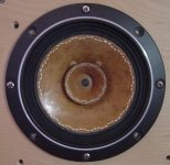
I am reposting a picture of a Fostex cone done by ultrakaz. This level of precision is really as good as you need to get to, so you do not need to be tense about errors or perfect looking blocks, which you will not get anyway. ultrakaz put 38 block sets down and it didn't hurt a thing. He tells me privately that he treated a pair of cheap Yamaha two way ($70 per pair) speaker systems and his girlfriend claims they are much clearer than his big system speakers. He is a bit undone by this from the sound of it.
I have never had to do more than apply the acrylic paint blocks to a baffle surface to completely control both reflected energy and diffraction from a sharp chine edge. Try this first and if it doesn't work for you, you can always make the pattern from other thicker materials.
Bud
If you can give me a few days I will be putting up pictures of the pen types needed, the paints needed and showing how a pair of Lowthers can be tamed.
If not, then go looking for Speed Ball A series pen tips and a handle to put them in. Also go to the local good hobby store and look for Poly S Flat Clear acrylic paint and Micro Scale Micro Gloss acrylic clear paint. Then toddle over to your good office products store, or, horrors, call around to find Polar Coordinate Graph paper.
Then dig up your ancient mechanical drawing set and get out the dividers. Do you have a set of extenders? You will need them.
Measure the distance from surround joint with cone, across the cone to it's opposite point and transfer that to a small section of the polar paper. Count back a couple of circles and that will be the outside edge of your upper, outer ring. Count back three more rings and that will be the lower edge of your lower ring of blocks.
Take that flat ring projection from one of the threads, this one even, and expand it until the outer edge of the biggest ring is one ring smaller than the inner diameter of your polar paper lower ring measurement. You may only get a section from letter sized paper and you will certainly have to stiffen it by gluing it to some thin cardboard. This becomes your template for application of the flat clear paint with the calligraphy pen. You can just as easily fill in the appropriate blocks on the Polar paper with pencil and use it directly, I do.
You use the pens upside down and pretty square to the cone surface you are working on The application pattern is two sets of lower blocks, and I would use the ones printed close to the cone for this, and then by eye put a set of upper blocks in between these two lower blocks, on the upper ring. Make sure you are leaving a small gap to the surround. For the 15 inch you will be using the widest pen available, This will be wide enough, even though it is not as wide as the printed paper blocks. Since you are eyeballing the placement just bring the upper blocks down a bit so that the space between rings is about the same as the widtht of the pen. A little more or less will be unimportant. If you find that the pattern row has wandered from perfectly concentric do not fret, wont alter a thing.
The flat clear paint will basically disappear for a while so you really cannot do one whole ring and then another very successfully.
Regardless of cone paper type use a pen dip per block and only drag one edge of the tip on the bottle lip, to remove big globs. If this is a soft short fiber cone material you probably will not see the pattern until you apply the gloss coat conformal coating material. If this is a calendered hard surface paper cone you will see the pattern pretty quickly, as it dries. If this is a poly cone don't use it just yet. Poly cones work quite well but you have to tooth the poly first, using a 3 to 4 k grit paper and a gloss pre-coat and overcoat process.
Be sure you pass the pen tip through an open flame till the protective coating burns off in a few seconds, otherwise the paint will not adhere to the brass and you will have no control over the flow event.
I would really suggest a cheap 8 inch paper cone PA driver as your first learning surface. You will improve the performance enormously with just two sets of rings and a dot in the middle of the dust cover, surrounded by just six of the pattern blocks to turn off the energy that would otherwise create a beam from this location.
The cone / dust cover joint will need to be treated and you use three rings here, one right at the joint, one up the cone wall and one out on the dome. same relative spacing, same number of pattern blocks. Round dots here are ok, rectangles get difficult to control at this small a size, on the 8 inch at least. The 15 inch woofer will need the same treatment, even though it will be a tedious bear to do it.
I am reposting a picture of a Fostex cone done by ultrakaz. This level of precision is really as good as you need to get to, so you do not need to be tense about errors or perfect looking blocks, which you will not get anyway. ultrakaz put 38 block sets down and it didn't hurt a thing. He tells me privately that he treated a pair of cheap Yamaha two way ($70 per pair) speaker systems and his girlfriend claims they are much clearer than his big system speakers. He is a bit undone by this from the sound of it.
I have never had to do more than apply the acrylic paint blocks to a baffle surface to completely control both reflected energy and diffraction from a sharp chine edge. Try this first and if it doesn't work for you, you can always make the pattern from other thicker materials.
Bud
Attachments
Bud,
I planned to use some cheap paper coned 15's that I have, and I'm pretty sure I can do at least as precise as pictured using some light markings first using a compass and protractor, although I may not try too get too accurate if I can match the cone color pretty well.
Thanks for the tips and I'll practice some as a refresher for using calligraphy pens.
I'm unclear about which things I do with the Poly S verses the Micro Gloss. It appears that one is a coating of the entire cone. Which is first, the blocks or the coating?
Lastly, what results were reported for the Fostex drivers? I have 2 pairs of FE206's that I can't bear to listen to, so I may treat them first.
John,
The Poly S is for the pattern, goes on first and is allowed to dry for a day. Then listen to one of the drivers.
Then coat the front side with one coat of the Micro Coat Gloss. Use a sable brush that just fits in to the bottle opening, move slowly as this stuff foams instantly and the bubbles take hours to break. Do not ever shake or stir just sort of gently rock the bottle, very slowly, to mix contents if they separate out.
First coat should go on using a circular painting fashion with as even and painterly a stroke as you can manage. This will not be a particularly even coat. Then wait a day and listen again, free air is fine, full range is fine. Likely two more coats of Gloss will do all that is needed. Apply them in alternate directions, with the second coat as vertical strips and the third as circular again. You can do these two back to back or wait for a few hours in between. Don't wait for a day though as these two need to interact a bit to give you a really smooth shiny surface.
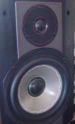
Here is the Fostex thread and I have posted his latest treated drivers, the Yamahas, below.
http://www.diyaudio.com/forums/showthread.php?s=&threadid=100391
Bud
The Poly S is for the pattern, goes on first and is allowed to dry for a day. Then listen to one of the drivers.
Then coat the front side with one coat of the Micro Coat Gloss. Use a sable brush that just fits in to the bottle opening, move slowly as this stuff foams instantly and the bubbles take hours to break. Do not ever shake or stir just sort of gently rock the bottle, very slowly, to mix contents if they separate out.
First coat should go on using a circular painting fashion with as even and painterly a stroke as you can manage. This will not be a particularly even coat. Then wait a day and listen again, free air is fine, full range is fine. Likely two more coats of Gloss will do all that is needed. Apply them in alternate directions, with the second coat as vertical strips and the third as circular again. You can do these two back to back or wait for a few hours in between. Don't wait for a day though as these two need to interact a bit to give you a really smooth shiny surface.
Here is the Fostex thread and I have posted his latest treated drivers, the Yamahas, below.
http://www.diyaudio.com/forums/showthread.php?s=&threadid=100391
Bud
Attachments
Thanks Bud,
I'm quite anxious to hear a with and without treatment with the blocks. If the micro gloss works well for cone doping, that's another tool for the arsenal, and based on one of your earlier posts it has advantages over other things used for doping.
I have 6 of the 15's, so I may get ambitious and EnABLE one, Mamboni another, and do both on a 3rd one. Tedious as it may be, it seems almost like fun compared to learning to measure. I downloaded ARTA yesterday, and the 100 page manual is daunting. Plus I have months of stuff I want to measure.
One last question, does the acrylic for the blocks soak into a paper cone very well. If not, would a PVA glue that soaks in be a good candidate, possibly negating the need for backside blocks?
Hi John,
The ability of the paint to soak into the paper depends upon many things. Calendering, rag content, fiber orientation and that is only on the front side. My experience is that in a direct A/B comparison of drivers from the same run of manufactured components, which I had access to at Nestorovlc Labs, approximately 70 % of the benefit of a both sides treated driver was available for a single side treatment.
That this is a totally qualitative assessment is obvious. The single side treatment is not "lacking" in some obvious manner. Just that with both sides controlled your threat assessment system, that is always on the lookout for some aberration in on going sonic pattens, is stimulated about that much less often by treating both sides.
This two sided treatment with the EnABL process is a pain due to baskets and other interferences with sight lines and pen manipulation.
In addition the EnABL process on both sides makes a cone more transparent to back wave events, that are then much more able to come right out and visit, with superb clarity.
For these reasons I am delighted with Dr. Mamboni's slick adaptation of felt to a known wave dissipation shape. The back side is controlled, and I am suspecting without a shred of proof, without either of the above mentioned problems. I am sure there will be some obstacles to overcome and C2C Thomas has noted one already, in recent Walsh Ohm posts. I do not think this is a worry for anything other than ambient signals in an OB system.
Using PVA on the backside is also an option to explore. It is not as good as the EnABL process on the front, but that is not where you are thinking about using it. It may be more transparent than the Mamboni process to back waves, but again, in an OB application this should not be a problem.
Bud
- Status
- Not open for further replies.
- Home
- Loudspeakers
- Multi-Way
- EnABL Processes