What is happening on with the green curve at circa 20kHz? It looks like hectic ringing or breakup.
Deon
Might be the brickwall filter of the soundcard; many of the 96/24 cards retain a hardware, non-defeatable 20 kHz lowpass filter on the ADC side of things. The only way to be really sure that a 20 kHz brickwall filter isn't there are factory specs that quote noise and distortion out to 40 kHz or higher.
If the specs are only quoted out to 20 kHz, there are good odds the soundcard has a 20 kHz brickwall filter that cannot be removed - unless you are comfortable circuit-tracing and removing SMD components.
Soongsc, I'm curious to see the Before and After pictures on the 3" driver, as well as an efficiency spec (I'm guessing 82~85 dB/meter/watt).
Last edited:
Thanks, Lynn, that could be it. It is scary to think what sometimes happens to the signal in the digital part of some systems. Me, I like digital, but I prefer good old analogue. There is something just so right and relaxing about the watching that black disc spin. It's just more hands on. But maybe I'm just giving my age away here. ")
Deon
Deon
Just a question about CSD how do you interpret the results, at what point is something considered an audible effect?
I could imagine it would be very easy making a mountain out of mole hill with these sought of measurements (still trying to decide whether the pun is intended)?
I could imagine it would be very easy making a mountain out of mole hill with these sought of measurements (still trying to decide whether the pun is intended)?
John, while letting the acoustic target match the ideal can improve CSD performance, the ideal target is not ideal. I think this would be more evident if you used a full range driver to do testing. I would
The point was and remains that if the drive is minimum phase, the target is minimum phase and the EQ is minimum phase, then the EQed driver response will have the same CSD as the target. It doesn't matter what the shape of thew target transfer function is or the frequency range of the driver.
Here are a couple of additional links to web pages I put up back in April when discussing this with Joachim:
Page 1 Midrange (before and after)
Page 2 Tweeter (Neo 3) (before and after)
Both CSD and burst response are shown, as well as HD (at a frequency where there was a significant resonance) since there was some (incorrect) speculation about the effect of the EQ on distortion.
Anyway, I'm not sure how this relates to current thread on Lynn's speaker. These were done using the UE.
Last edited:
Green curve is the phase which corresponds with the cone breakup mode. When you have cap and cone not reaching breakup mode at the same time, that is a point difficult to compensate for no matter what.What is happening on with the green curve at circa 20kHz? It looks like hectic ringing or breakup.
Deon
I think we got into the discussion when Lynn mentioned stored energy.The point was and remains that if the drive is minimum phase, the target is minimum phase and the EQ is minimum phase, then the EQed driver response will have the same CSD as the target. It doesn't matter what the shape of thew target transfer function is or the frequency range of the driver.
Here are a couple of additional links to web pages I put up back in April when discussing this with Joachim:
Page 1 Midrange (before and after)
Page 2 Tweeter (Neo 3) (before and after)
Both CSD and burst response are shown, as well as HD (at a frequency where there was a significant resonance) since there was some (incorrect) speculation about the effect of the EQ on distortion.
Anyway, I'm not sure how this relates to current thread on Lynn's speaker. These were done using the UE.
I wish SoundEasy had the potion to display CSD in periods, it will more easily show damping relationship with frequency since it is audibly desireable to not only have sound decay fast, but have the same damping characteristic.
I will study the links some more.
I wish SoundEasy had the potion to display CSD in periods, it will more easily show damping relationship with frequency since it is audibly desireable to not only have sound decay fast, but have the same damping characteristic.
I suggested that to Bohdan probable 5 or 6 years ago. It would not be hard. All that would need to be done is to rescale the time values by multiplying by f. The problem is with the way Bohdan stores his data. Anyway, I'm out of the the SE/UE loop.
Some times I measure with 48KHz sample rate setting sometimes I use 96KHz, since UE runs at 48KHz under this case measurement at 96KHz can produce some funny graphs. However, I don't see it effecting what I am trying to present.Might be the brickwall filter of the soundcard; many of the 96/24 cards retain a hardware, non-defeatable 20 kHz lowpass filter on the ADC side of things. The only way to be really sure that a 20 kHz brickwall filter isn't there are factory specs that quote noise and distortion out to 40 kHz or higher.
If the specs are only quoted out to 20 kHz, there are good odds the soundcard has a 20 kHz brickwall filter that cannot be removed - unless you are comfortable circuit-tracing and removing SMD components.
Soongsc, I'm curious to see the Before and After pictures on the 3" driver, as well as an efficiency spec (I'm guessing 82~85 dB/meter/watt).
UE Eqed
An externally hosted image should be here but it was not working when we last tested it.
Before
An externally hosted image should be here but it was not working when we last tested it.
The driver sensitivity is speced at 87db/M/W, after treatment, it reduced about 1db. But what difference to you think it will make?
My experience is this:Just a question about CSD how do you interpret the results, at what point is something considered an audible effect?
I could imagine it would be very easy making a mountain out of mole hill with these sought of measurements (still trying to decide whether the pun is intended)?
Technically, the high level after time zero is like the driver itself mixing noise into oncoming playback music.
What it sounds like is a more difficult thing to explain unless you listen to before and after. But if you compare two that have pretty much similar frequency response, you can relate the sonic signature with specific CSD long decays. Generally, I find some 12db difference in CSD more obvious.
You mentioned earlier that you will use auto-transformers for the horn attenuation. I have to ask - Why? What is the benefit over a 2 resistor network?...Paul Klipsch was using autoformers for horn attenuation as early as 1959.
Gary Pimm and I had a discussion about this very topic some time ago. Transformers are nice, but their disadvantage here is that they magnify the driver's impedance curve more and more the more you attenuate. So you end up having to put a damping resistor across it to keep a sane impedance for the crossover. Now instead of just a transformer, you have a transformer and a resistor. What is the advantage over 2 resistors?
I like transformer coupled circuits, but in this case I don't understand the advantage.
You mentioned earlier that you will use auto-transformers for the horn attenuation. I have to ask - Why? What is the benefit over a 2 resistor network?
Gary Pimm and I had a discussion about this very topic some time ago. Transformers are nice, but their disadvantage here is that they magnify the driver's impedance curve more and more the more you attenuate. So you end up having to put a damping resistor across it to keep a sane impedance for the crossover. Now instead of just a transformer, you have a transformer and a resistor. What is the advantage over 2 resistors?
I like transformer coupled circuits, but in this case I don't understand the advantage.
I recall that when the LS3/5a crossover was redesigned for the newer B110 the autotransformer for tweeter attenuation was eliminated in favor of a resistive network. I can not imagine how an autotransformer would be better due to hysteresis and other potential problems.
...just a guess: permits smaller values for x-over capacitors and inductors as the impedance of horn driver (for a specific crossover point) increased as it's seen through autoformer? Having an equivalent bigger speaker impedance as a result, more suited for low power amps of those days?
Last edited:
Some times I measure with 48KHz sample rate setting sometimes I use 96KHz, since UE runs at 48KHz under this case measurement at 96KHz can produce some funny graphs. However, I don't see it effecting what I am trying to present.
UE Eqed
An externally hosted image should be here but it was not working when we last tested it.
Before
An externally hosted image should be here but it was not working when we last tested it.
The driver sensitivity is speced at 87db/M/W, after treatment, it reduced about 1db. But what difference to you think it will make?
Can you discuss the results further. I am not sure what you have done to the driver.
It seems the first plot shows lower initial noise/distortion but slow decay, but the second has higher initial noise/distortion but faster decay. I am not sure what would be considered better
Last edited:
I think the point we left off at was whether someone can to better without using DSP.Can you discuss the results further. I am not sure what you have done to the driver.
It seems the first plot shows lower initial noise/distortion but slow decay, but the second has higher initial noise/distortion but faster decay. I am not sure what would be considered better
You mentioned earlier that you will use auto-transformers for the horn attenuation. I have to ask - Why? What is the benefit over a 2 resistor network?
Gary Pimm and I had a discussion about this very topic some time ago. Transformers are nice, but their disadvantage here is that they magnify the driver's impedance curve more and more the more you attenuate. So you end up having to put a damping resistor across it to keep a sane impedance for the crossover. Now instead of just a transformer, you have a transformer and a resistor. What is the advantage over 2 resistors?
I like transformer coupled circuits, but in this case I don't understand the advantage.
There are several reasons:
1) Subjective. Gary Pimm and I did some auditioning of the "sound" of series resistors, and discovered that something as modest as a 0.5 ohm series R created a noticeable dynamic flattening of Gary's ribbon tweeter. I also tried the same comparison with the prototype LTO loudspeaker to attenuate the compression driver, and heard the same result - pretty obvious dynamic flattening. For some reason, shunt resistors are much less audible. I have no idea why, but that's what I hear.
2) Let's put aside the subjective stuff and go to real things that are measurable (audibility of series resistors is one of those woo-woo things I'm not going to defend).
Using a 12 dB autoformer (like the Klipsch), the impedance of the HF driver is multiplied 16 times (impedance is the square of the turns ratio). For a large-format compression driver, the impedance at the terminals of the driver varies from 12 to 40 ohms; the autoformer multiplies this to 192 to 640 ohms.
There is a 16 ohm shunt resistor in front of the autoformer (between the highpass filter and the autoformer). Since the resistances of the shunt resistor and the autoformer are in parallel, the load resistance seen by the highpass filter varies between 14.77 and 15.61 ohms, a much smaller variation than the 12 to 40 ohms of the driver itself.
There is also a secondary benefit that regardless of the source resistance of the highpass filter, it is shunted by the 16-ohm resistor, which the autoformer divides down to 1 ohm. So if I choose to use a 3rd-order highpass filter, with high impedances at low frequencies (thanks to the last series C), it doesn't matter, since that impedance is in parallel with the 16-ohm shunt resistor, and the autoformer divides that by 16.
The autoformer presents the compression driver with a source impedance between zero and one ohm, regardless of crossover topology. The highpass filter sees a load that only varies over a 6% range, a much smaller variation than an L-pad would present. Since impedance variations for compression drivers + horns can vary sharply over narrow frequency ranges, this degree of isolation is useful when designing the highpass filter. Otherwise, for a precise control of frequency and phase response, it might be necessary to use multiple notch filters to exactly compensate for driver impedance variations.
3) Nobody likes big clunky transformers. Fortunately, the autoformer or transformer can be very small and use a high-quality 80% nickel core (similar to a studio-grade line transformer), since the troublesome bass is efficiently filtered by the highpass filter of the crossover. Nearly all of the core size of a transformer is due to the requirement to pass frequencies lower than 100 Hz; it that isn't there, it can be much smaller, which also reduces stray capacitance, which extends the HF bandwidth (small is beautiful for HF response). Distortion in a well-designed transformer is very low from 500 Hz to 10 kHz, which by happy coincidence is right where this transformer operates.
4) I like the sound better. L-pads sound duller and more congested to me. Even the cheap little Klipsch autoformer has a more sparkly and "alive" sound, while also measuring better as well.
Last edited:
Thanks Lynn, that's the sort of info I was looking for. I can certainly understand the lower impedance at the the output of the transformer. I have no idea if that sounds good or not, but it's there. The flatter impedance seen by the crossover may have some benefit, too.
It would be nice to measure a few implementations to see what the differences are.
BTW, got a source for good crossover autoformers?
It would be nice to measure a few implementations to see what the differences are.
BTW, got a source for good crossover autoformers?
Compound woofer systems do tend to reduce event order HD. Isobaric systems , not so much.
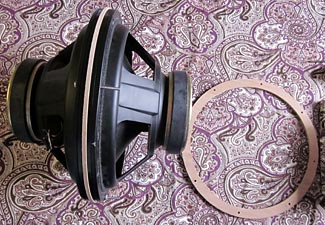
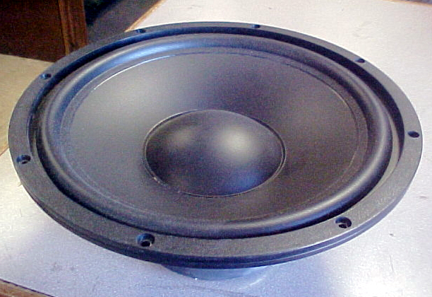
Your analysis assumes a 4L volume. With a 1L volume, you see a significant reduction in even order. I threw around some numbers, and came up with something that may surprise- many 12"s have a litre or less of volume inside the cone. If mounted face to face and spacing minimized, you could have <2L of enclosed volume, and thus achieve a more meaningful reduction than when using the 4L your model supposed. With a JBL 2213, 123A, 123A-3, 2213H, one could get enclosed volumes of < 1L, as they are very shallow cones, with accordion surrounds.
Consider that many other subwoofers have very large dustcaps, and the volumes shrink rapidly with decreasing driver diameter, and the enclosed volume can be quite modest.
Take a look at the attached- you can approximate some numbers if you wish.
An externally hosted image should be here but it was not working when we last tested it.
And then there is the question of "how audible is an autoformer compared to a true isolation transformer?" I cannot abide the low level garble I hear in every autoformer, including mine, that I have auditioned.
Do consider, the autoformer is still a phase flipping transformer, but some portion of the windings have opposite phase signal flowing through them, just slightly out of perfect alignment at 500 Hz but progressively less aligned as the inevitable capacitance has it's way with the output signal.
PM me Pano, I am building some 2:1,4:1,8:1 units on the core set for the Berringer device.
Bud
I'd be on board for a true transformer instead of an autoformer - nickel core please, with taps at -12, -13, -14, and -15 dB. No need for a large core, with a brickwall highpass filter in the 500~700 Hz region, and the compression driver never seeing more than 20 watts under any circumstances.
I imagine a true transformer would be a bit easier to wind, with no need to connect primary and secondary together, and more freedom to select the right gauge wire for the job.
Listening to "Caliban's Dream" on the UK release of "Isles of Wonder" - what fun! Thanks to Amazon.co.uk for offering the double-disc set. Great recording quality.
Last edited:
- Home
- Loudspeakers
- Multi-Way
- Beyond the Ariel