I have a feeling I'm turning the page again, but everyone will doubtless read back for Lynn's fabulous educational musings!
@GregOH1: Love that horn setup, my friend! Thanks for sharing.")
You would think after near 100 years of HiFi that we are near some sort of total understanding. Your remarks about speaker drivers having a natural bandwidth and Laurie Fincham's thoughts on inductance and resistance make a lot of sense. The more musical drivers do have low inductance and a resistive load, and are easier to design filters for. My own observation is that anything above (say) 0.3mH at 3kHz gets awkward for second order filters on 6 ohms. 0.2mH for third order.
I was thinking about your near second order Linkwitz-Riley filters on the Ariel II:
The Ariel, Part II
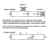
You mention you prefer the filters in phase for matching reasons, but as we know that will (tend to) give you a notch in the frequency response. But just look at your red impedance matching circuit: isn't that crying out for the 10 ohm resistor to be replaced by a filler midrange driver, a la Bang & Olufsen? That corrects the impedance and fills the notch.
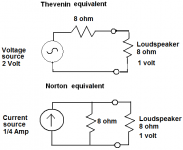
My own "epiphany" on amplifiers came with looking at the Thevenin and Norton equivalents, which suggest that it's really all about the topology and not the devices, and that the old-fashioned idea of matching source and load is really correct. Another came more recently, when that striking 3rd order Butterworth observation suggested a very deep relationship between source and load. After all, wouldn't it be all a lot easier if the amplifier actually knew what sort of load it faces before it tries to drive it? Or looking at it another way, the filter incorporates a model of the driver.
@GregOH1: Love that horn setup, my friend! Thanks for sharing.
You would think after near 100 years of HiFi that we are near some sort of total understanding. Your remarks about speaker drivers having a natural bandwidth and Laurie Fincham's thoughts on inductance and resistance make a lot of sense. The more musical drivers do have low inductance and a resistive load, and are easier to design filters for. My own observation is that anything above (say) 0.3mH at 3kHz gets awkward for second order filters on 6 ohms. 0.2mH for third order.
I was thinking about your near second order Linkwitz-Riley filters on the Ariel II:
An externally hosted image should be here but it was not working when we last tested it.
The Ariel, Part II
You mention you prefer the filters in phase for matching reasons, but as we know that will (tend to) give you a notch in the frequency response. But just look at your red impedance matching circuit: isn't that crying out for the 10 ohm resistor to be replaced by a filler midrange driver, a la Bang & Olufsen? That corrects the impedance and fills the notch.
My own "epiphany" on amplifiers came with looking at the Thevenin and Norton equivalents, which suggest that it's really all about the topology and not the devices, and that the old-fashioned idea of matching source and load is really correct. Another came more recently, when that striking 3rd order Butterworth observation suggested a very deep relationship between source and load. After all, wouldn't it be all a lot easier if the amplifier actually knew what sort of load it faces before it tries to drive it? Or looking at it another way, the filter incorporates a model of the driver.
Attachments
The Ariel is acoustically a 4th-order system, close to a LR4. Electrically it is a low-Q 2nd-order, but the drivers add their own characteristics, increasing it to 4th-order. In the normal-phase connection, the mids and tweeter are within 5 degrees degrees of each other, which is a key design feature.
The huge downside of B&O filler-driver technique is the drivers are in phase quadrature from each other - that is, there is a 90-degree phase angle between the woofer and filler, another 90-degree phase angle between the filler and tweeter, and the woofer and tweeter are 180 degrees apart. That creates a very strange polar pattern, with audible nulls as you move up and down. True, some folks might want to try a WFTFW layout, but I suspect it would have a symmetric but also very complex polar pattern. There would be a lot of widely-spaced drivers that would be completely out of phase with each other, and I can't see how that would sound good.
I worked for several years designing and patenting the Shadow Vector Quadraphonic decoder before starting in on loudspeakers. I became very sensitive to phase angles between pairs of widely spaced loudspeakers, and can also hear the same thing for closely spaced drivers as well. So I try and keep the inter-driver phase angle as small as possible, using the null technique to measure the accuracy of phase-tracking.
I find the inter-driver phase angle far more audible than overall system phase shift, which may or may not be audible, depending on recording technique. Inter-driver phase angle, though, is audible on all program material, at all times, and when excessive, is quite noticeably disjointed-sounding. When phase angles are below 10 degrees and response is smooth, the system sounds like a single-driver system, not a multiway.
The amplifier's task, as I see it, is to ignore the load. Loudspeakers have many, many resonances, not just the obvious lumps in the impedance curve. You want a surprise, do a waterfall/CSD on the current flow of a loudspeaker (measure across a 0.1 ohm resistor in series with the loudspeaker system). You'll see all kinds of ugly-looking high-Q resonances in the time domain. This debris appears on the plates of the power tubes, or the emitters of the power transistors. If the amplifier has feedback, it gets echoed back to the input devices, and possibly cross-modulated with the amplifier's own distortion signature. There are no distortionless amplifiers, and there are no loudspeakers free of resonances. Marketers would like us to think otherwise, but it ain't so.
To that end, it is desirable the instantaneous output impedance of the amplifier is free of switching artifacts (Class AB, I'm looking at you). The ideal amplifier simulates a small but constant resistance across the whole duty cycle, and is not affected by the back-EMF products from the loudspeaker, which are highly resonant and distorted. Global feedback can decrease and linearize the output impedance, but it does not completely remove the Class AB switching transition.
To make the momentary shift in output impedance go away completely, it would take an infinite amount of feedback, a carefully zero-balanced feedforward technique, or accept the greatly reduced power output and stay in Class A over the entire duty cycle. Since infinite feedback is not available, and feedforward techniques that are stable under dynamic and overload conditions not trivial to design, I prefer Class A operation as the best interface between resonant, distorted loudspeakers and an amplifier with a nonzero output impedance.
Last edited:
I wondering when trying to measure current CSD, whether we are seeing measurement equipment characteristics or the actual response. Probably you are still measuring the voltage in practice but take reference points such that they correspond with current?...
The amplifier's task, as I see it, is to ignore the load. Loudspeakers have many, many resonances, not just the obvious lumps in the impedance curve. You want a surprise, do a waterfall/CSD on the current flow of a loudspeaker (measure across a 0.1 ohm resistor in series with the loudspeaker system). You'll see all kinds of ugly-looking high-Q resonances in the time domain. This debris appears on the plates of the power tubes, or the emitters of the power transistors. If the amplifier has feedback, it gets echoed back to the input devices, and possibly cross-modulated with the amplifier's own distortion signature. There are no distortionless amplifiers, and there are no loudspeakers free of resonances. Marketers would like us to think otherwise, but it ain't so.
...
Actually and MFTFM format can yield a smoother vertical polar response than an LR2 system. I designed and build such a system back in 2001.
TP3-project14
The electrical crossover was quite complex, as can be inferred by the number of elements in each section.
The simulated vertical response of the MFTFM system is compared to an LR2 MTM at the bottom of this page:
TP3-project13
(If the web pages don't come up imediately, click the blue "Impatient?" at the lower right of the way back page.
I still have that speaer system sitting in a corner of my room.
I would think Lynn is talking about measuring the impulse response of the conductance (the inverse of the impedance) which both of course contain the same information.I wondering when trying to measure current CSD, whether we are seeing measurement equipment characteristics or the actual response. Probably you are still measuring the voltage in practice but take reference points such that they correspond with current?
In practice you can do that with fixing the voltage (voltage drive) or fixing the current (current drive) or anything else (arbitrary drive impedance), as long as you measure both pulses simultaneously (that of driver current and terminal voltage) you can obtain the impedance (or admittance) pulse by division. In theory with a linear system it would always be the same result no matter how you varied voltage and/or current and exitation signal, but real world drivers show differences induced by the way how and to what extent the driver's motion was exited and how electrical damping was at work.
With modern log-sweep plus convolution methods you can also isolate distortion components.
Any external exitation other than from the VC's own inital motion can be found by inspecting the impulse. When you display it in CSD or spectrogram view with time as Z-axis (not periods) you can, for example, clearly identify internal cabinent reflections/modes since the appear as delayed pulse trains (set of ridges) whereas resonances in the driver itself are not delayed (or only very short delays) and appear as narrow-band decays.
By trying to correlate impedance pulse data with spl pulse data take simultaneously you can gather a lot of knowledge what the driver is doing and what the cabinet is doing, what the effect of stuffing is, etc.
What you say is true. However, when we want to explore the effects of amplifier feedback on the CSD, the time is so closely overlapping with the main response, and additionally, the method of pickoff will effect that actual CSD result. The interaction is so interrelated that I could change the characteristic of the interconnect and the impulse will change.I would think Lynn is talking about measuring the impulse response of the conductance (the inverse of the impedance) which both of course contain the same information.
In practice you can do that with fixing the voltage (voltage drive) or fixing the current (current drive) or anything else (arbitrary drive impedance), as long as you measure both pulses simultaneously (that of driver current and terminal voltage) you can obtain the impedance (or admittance) pulse by division. In theory with a linear system it would always be the same result no matter how you varied voltage and/or current and exitation signal, but real world drivers show differences induced by the way how and to what extent the driver's motion was exited and how electrical damping was at work.
With modern log-sweep plus convolution methods you can also isolate distortion components.
Any external exitation other than from the VC's own inital motion can be found by inspecting the impulse. When you display it in CSD or spectrogram view with time as Z-axis (not periods) you can, for example, clearly identify internal cabinent reflections/modes since the appear as delayed pulse trains (set of ridges) whereas resonances in the driver itself are not delayed (or only very short delays) and appear as narrow-band decays.
By trying to correlate impedance pulse data with spl pulse data take simultaneously you can gather a lot of knowledge what the driver is doing and what the cabinet is doing, what the effect of stuffing is, etc.
There is no effect of "amplifier feedback" on any obtainable impulse response (within the audio freq. range, say up to 100kHz or so) other than that of its equvialent output impedance which can be assumed to linear (but complex, of course). If it is not linear (that is, signal dependent), it is not a serious amplifier to begin with.
A 0.1 Ohms measurement shunt has negleglible influence btw, also you can put that inside the feedback loop of the amp, and if you still feel uncomfortable use a clamp-on inductive current probe on one of the speaker wires.
And as I stated, except for nonlinearites in the speaker itself, any change of drive impedance does not, and cannot, change the impedance impulse of the speaker.
I'm not clear about what effect you actually want to measure.
My personal experience is that there are so many things that effect the sound of equipment, it really is a maze of things that need to be considered. I recall have measured distortion changes with different impedance compensation circuits which was measured while driving the speaker. The idealistic scenario of having a fixed resistor to evaluate amplifier performance is really a very basic test. I would have assumed more stringent standard tests would have evolved, but seems like none has been popularly adapted.
Nothing all that radical. 15" high efficiency bass driver in a resistive-vent cabinet with attention paid to diffraction reduction, the AH425 Azurahorn with a large-format compression driver, and a high-quality supertweeter.
Preliminary measurements are comparable to the Ariel in the time and frequency domains, with a 7~8 dB gain in efficiency and a headroom increase of 10~15 dB. Sounding good at this point, but much development remains. I hope to make the RMAF deadline, but can't say for sure at this point.
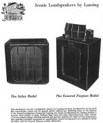
In a way, it is a modern development of the Jim Lansing Iconic that debuted in 1936. Very few music sources back then had content above 8 kHz; at high frequencies, shellac 78's were mostly noise, and the Bell Telephone intercity relays for the AM radio networks were sharp-cut at 8 kHz. A few people could pick up Major Armstrong's Yankee FM Network on the East Coast, but that was about it for wideband (and low distortion) audio. No-one outside of Germany had heard of magnetic tape, and AC biasing had not been invented yet. But the basic format of the Iconic lives on as large-format studio monitors.
Modern LP's, if played with a moving-coil cartridge, have content above 30 kHz, and high-resolution digital extends to 40 kHz and above. So the system uses a supertweeter to extend the bandwidth above the usual horn frequency range.
No, the styling does not echo the Iconic, and the drivers do not use field coils to energize the magnets.
Preliminary measurements are comparable to the Ariel in the time and frequency domains, with a 7~8 dB gain in efficiency and a headroom increase of 10~15 dB. Sounding good at this point, but much development remains. I hope to make the RMAF deadline, but can't say for sure at this point.
In a way, it is a modern development of the Jim Lansing Iconic that debuted in 1936. Very few music sources back then had content above 8 kHz; at high frequencies, shellac 78's were mostly noise, and the Bell Telephone intercity relays for the AM radio networks were sharp-cut at 8 kHz. A few people could pick up Major Armstrong's Yankee FM Network on the East Coast, but that was about it for wideband (and low distortion) audio. No-one outside of Germany had heard of magnetic tape, and AC biasing had not been invented yet. But the basic format of the Iconic lives on as large-format studio monitors.
Modern LP's, if played with a moving-coil cartridge, have content above 30 kHz, and high-resolution digital extends to 40 kHz and above. So the system uses a supertweeter to extend the bandwidth above the usual horn frequency range.
No, the styling does not echo the Iconic, and the drivers do not use field coils to energize the magnets.
Attachments
Last edited:
Ah, and I thought it was going to be a little speaker called the Lynette! I've been doing some experiments with cone breakup from the bass. You really notice it far less if it is in phase with the tweeter. In fact hardly at all. Alas there are limits to what you can do on a conventional flat baffle. But time aligned seems to allow you to do an almost perfect job. This should be good.With the freestanding, low-diffraction Azurahorn and supertweeter, the system is easily time-aligned. The decay-to-zero for the impulse response is around 0.5~0.7 mSec, similar to the Ariel. I'll admit this is the first time I've ever seen impulse response like this for a large-format compression driver, though - the 425 Hz LeCleac'h Azurahorn is really quite remarkable in the time domain. The matching of the exit angle of the compression driver and the entrance of the horn is probably helping as well.
The high-efficiency bass driver is also well-behaved above its working range, which greatly simplifies crossover design.
The high-efficiency bass driver is also well-behaved above its working range, which greatly simplifies crossover design.
Last edited:
In the meantime I took a route " back to Ariel" well not quite but close enough. Bought a used Living Voice Avatars which are to me very close in philosophy and drivers used to Ariel . Granted it's a vented design and not a transmision line but those paper vifas with scan speak tweeter in D'appolito config should sound quite similar , correct me if I'm wrong as I never heard Ariel . So how do they sound? Surprisingly open and dynamic in very , very small room and quite pleasant in a big one. What I like the most is tonal quality of the speaker . No, it's not Tannoy nor altec luscious midbass with midrange presence but those old vifas surely have some of the vintage drivers magic. Yes , the "boxines " of the sound is very present but unlike in many speakers it doesn't bother me much and they are quite universal performer in very reasonable package ( not exactly cheap ) I guess what I'm trying to convey here in my poor English is "keep your Ariels around" They might get handy in bad times or "in between" times. Rgrds, L

In the meantime I took a route "back to Ariel" well not quite but close enough. Bought a used Living Voice Avatars which are to me very close in philosophy and drivers used to Ariel. Granted it's a vented design and not a transmision line but those paper vifas with scan speak tweeter in D'appolito config should sound quite similar, correct me if I'm wrong as I never heard Ariel. So how do they sound? Surprisingly open and dynamic in a very, very small room and quite pleasant in a big one. What I like the most is tonal quality of the speaker. No, it's not Tannoy nor Altec luscious midbass with midrange presence but those old Vifas surely have some of the vintage driver's magic. Yes, the "boxiness" of the sound is very present but unlike in many speakers it doesn't bother me much and they are quite universal performer in very reasonable package (not exactly cheap) I guess what I'm trying to convey here in my poor English is "keep your Ariels around" They might get handy in bad times or "in between" times. Rgrds, L
Don't worry, the Ariels will be kept around, doing rear-channel duty if nothing else. The Ariels don't sound boxy at all; they were originally designed to mimic the sound of stacked Quad ESL57's, and they sound very much like electrostats - quick and light on their feet, due to the time response and low diffraction signature (no sharp box edges).
The new speakers sound like really big electrostats, with more dynamic and tonally vivid bass than panel speakers. The "horn" aspect of the presentation is the spatial presentation; the solo performers are in-the-room, not behind the plane of the speakers, as they would be with most electrostats. Pianos sound like they are in the room, not somewhere else, for example. This is most likely is a function of the large radiating area of the bass and horn drivers, along with low IM distortion.
There's also a 70mm Stereophonic Sound widescreen movie aspect to the presentation - it's a big sound, not surprising considering the enormous headroom of the large-format compression driver and the 15" bass driver. Many of you never heard what widescreen movie theaters sounded like in the 1950's and 1960's - completely different than modern THX screech and boom - but the new speakers bring back memories of seeing Ben-Hur, Spartacus, West Side Story, My Fair Lady, and Lawrence of Arabia. I lived in Kobe, Japan, and later Hong Kong, and our family saw these movies in their full 70mm widescreen splendor (and six-channel all-analog mag-track sound) at the Asian premieres.
You can keep your digital-cinema and THX sound; no comparison at all to 70mm Technicolor on a curved screen with three theater speakers (powered by all-analog vacuum-tube electronics) behind the screen. Stereophonic sound was still fairly new in those days, and hearing what sounded like a full symphony orchestra right behind the screen made the audiences gasp in surprise. Nowadays, it's all about very loud SFX explosions and extended battlescenes with obvious-looking CG rendering, not the same thing.
Last edited:
- Home
- Loudspeakers
- Multi-Way
- Beyond the Ariel