Gary,
I hope the opera was wonderful. It must be quite a rush, even though it's a lot of work' to conduct one of those.
Quite a rush indeed! It was a great experience. I do plan to write more about this, but not until after this weekend's performances.
Did you spring for the Apollo option for your TD drivers?
I did for the TD15M's, but not for the TD15H's. The latter were purchased secondhand. The price difference between Apollo new and non-Apollo used was substantial!
Gary Dahl
The usual conflict between me n wood. On the other hand, the DCX2496 is currently undergoing surgery with Jan's control board, the drivers are EnABL'd and Randy, of the wild nude Lowther stand, has shown interest in making fitting nude Lowther fixtures for the boxes. In fact, yet another dithering redesign of the woofer box is underway, just to provide some more dramatic substance for Randy's work to set upon.
So, just as slow as I expected.
So, just as slow as I expected.
How does this model...?
Hi Guy's,
Very glad this thread is active again and more interesting ideas to ponder...
When running in big pro bass drivers its common practice to place the left and right speakers face to face, reverse polarity on ONE speaker, turn up the 800 watt power amps , put on some killer bass tracks and leave home for the weekend... Anyone who has tried this knows that even OUTSIDE the building the audible effect of reversing polarity on one channel is huge.
In normal domestic systems try reversing polarity on one of your bass drivers and have a listen. The effect is very easy to hear and feel if you have a true full range system.
Now my suggestion / question...
In recent threads close attention is paid to the nature of sound waves generated by drivers mounted on open baffles, and specifically how the back wave and front wave integrate / effect each other.
All the sims assume that the drivers are true point sources i.e. instruments and voices etc radiating 360 degrees in all directions. But I suspect this is NOT the case, not even with a " naked " driver hanging from a thread.
As all sound waves in the audible ( ignoring sub bass which we feel through our bodies ) 20Hz to 20KHz are only detectable by changes in air preasure- compression and rarefaction- we have an elephant in the room. i.e. When our driver cone pumps forward and COMPRESSES ( INCREASE IN AIR PREASURE ) the air to send us the note / drum strike, transient etc this sound wave rushes out in all FRONT facing directions... meanwhile the same forward pump motion of the cone causes an inverse RAREFACTION ( DROP IN AIR PREASURE) and this sound wave front rushes out in all REAR facing directions.
So when the two opposing forces meet what happens....? How do they mix n match? Do the current sims and models reflect this opposing force reality? If not can they be easily tweaked to compare the results?
So if I am correct, the sims and models should be able to show this fundamental and real world effect clearly. If they can’t does it mean the real world is wrong and the world of “ Matrix simulations “ is correct? In climate modelling they don’t trust any computer simulations to “ forecast” the future weather until the same simulation can accurately reproduce the KNOWN weather of recent years i.e. a few years, up to a few hundred years, of well documented day to day global weather. This is known as PRE-CASTING climate modelling.
Can we as music lovers benefit from this technique? Are we measuring the right things...? As always more questions than answers, over to you guys!
All the best
Derek.
PS I have an interesting FE sim of an 18 inch bass driver in an open baffle, its too big to post, who can shrink it and post it for me? Thanks.
Hi Guy's,
Very glad this thread is active again and more interesting ideas to ponder...
When running in big pro bass drivers its common practice to place the left and right speakers face to face, reverse polarity on ONE speaker, turn up the 800 watt power amps , put on some killer bass tracks and leave home for the weekend... Anyone who has tried this knows that even OUTSIDE the building the audible effect of reversing polarity on one channel is huge.
In normal domestic systems try reversing polarity on one of your bass drivers and have a listen. The effect is very easy to hear and feel if you have a true full range system.
Derek.
This is basically a room effects, modal excitement phenomena for a widely space dipole.
Here are the measurements to confirm the above simus on the concept of consecutively min phase behavior:
Measurements have been done in door with a NEO3 tweeter in round OB of roughly 43cm diameter.
Hence the 0.7ms do not exactly correspond with the simu where a 1ms delay was shown.

Anyway – the measurements where done in relation to simus (0.7 / 1) – meaning at the nulls and peaks and also well below first OB peak to give a good visual grip on the subject ( just time scaling is different ).
First the IR – with a particularly clear displayed second part of the doublet:

and the well known OB FR – not any different for this particular one except the pronounced nulls and peaks due to the circular baffle (in need to keep issues seperated):

Now switching back into time domain and showing measurement sine burst – comparing simu and measurement (In the simu compare to the BROWN trace):
Second null :


second peak :


first null


first peak :


below first peak :


Though measurements are only „as good as it gets“ - the concept I guess is clearly shown to apply in audio reality – no?
We can see that correlation between simu and measurements is actually excellent (taking into account the band pass character of a real world speaker like the NEO 3)
Also clearly seen is that the two parts of consecutively min phase behaviour are separated pretty sharp one from the other – even better measurable than I've hoped for.
The last important point to be aware of is that this goes all the way down in frequency – there is no limit here where this concept applies.
So we now can possibly proceed to the „fun part“ of discussing how to EQ out (or not) any „consecutively min phase behaviour“...
")
Michael
Measurements have been done in door with a NEO3 tweeter in round OB of roughly 43cm diameter.
Hence the 0.7ms do not exactly correspond with the simu where a 1ms delay was shown.
Anyway – the measurements where done in relation to simus (0.7 / 1) – meaning at the nulls and peaks and also well below first OB peak to give a good visual grip on the subject ( just time scaling is different ).
First the IR – with a particularly clear displayed second part of the doublet:
and the well known OB FR – not any different for this particular one except the pronounced nulls and peaks due to the circular baffle (in need to keep issues seperated):
Now switching back into time domain and showing measurement sine burst – comparing simu and measurement (In the simu compare to the BROWN trace):
Second null :
second peak :
first null
first peak :
below first peak :
Though measurements are only „as good as it gets“ - the concept I guess is clearly shown to apply in audio reality – no?
We can see that correlation between simu and measurements is actually excellent (taking into account the band pass character of a real world speaker like the NEO 3)
Also clearly seen is that the two parts of consecutively min phase behaviour are separated pretty sharp one from the other – even better measurable than I've hoped for.
The last important point to be aware of is that this goes all the way down in frequency – there is no limit here where this concept applies.
So we now can possibly proceed to the „fun part“ of discussing how to EQ out (or not) any „consecutively min phase behaviour“...
Michael
Last edited:
A good „starter“ to the paramount implications of the concept of „conscecutilely min phase behaviour“ may present a question to ask for at first when we dive into EQing of that form of distortion.
The question arises :
“how actually do we check if any EQing was applied sufficiently?”
Lets take a look at the simu / measurements at the first null – at a frequency of 1360Hz where the marker is set :
The ususal answer would be :
Easy !
We take a measurement !
Exactly like shown in the frequency response above !
– no ?
BUT :
comparing the FR plot and the time domain plot for this particular 1380Hz (at the first null) - where destructive interference happens – we see that after the first min phase period there is considerable less signal than the roughly -10dB indicated by ARTA in-room measurement.
The measurement was gated at the usual 4ms to avoid any room reflections creeping in. This means that ARTA has actually calculated only data within that time period. This also means that this value of -10dB does neither reflect correctly for the the first period of min phase behaviour nor for the following.
So we come to the simple but pretty scary conclusion :
Our usual tools in measurement – eg FR plot - are flawed and totally useless when it comes to „consecutively min phase behaviour“ .
Perfectly EQing this FR first notch, with a standard equalizer like the DCX2496 for example, would be possible without any question (at least as it seems at a first glace) – but the measurement we would rely on to verify would only show us a fake !
So we have to be aware that such EQing must be ex amend more closely - and also in the time domain - to tell if we *really* got any perfect EQing or not.
Is there agreement so far?
Michael
Last edited:
The problem with your entire argument is that you are addressing a problem of what happens above the dipole peak, well above what would be considered the useful frequency range of a dipole. The response should be LP filtered and well attenuated by then. Above the dipole peak the response is just that of two uncorrelated sources interacting with each other.
The problem with your entire argument is that you are addressing a problem of what happens above the dipole peak, well above what would be considered the useful frequency range of a dipole. The response should be LP filtered and well attenuated by then. Above the dipole peak the response is just that of two uncorrelated sources interacting with each other.
Actually I don't get your point.
CMP behaviour is part and parcel to OB – be in the „true dipole range“ well below first peak or be it in the „correlated inverse monopole range“ elsewhere above.
I guess I have shown OB to be a CMP system all the way by theory (my „concept“), by simu and by measurement too - I mean - two point sources separated by some distance simply *must* be CMP - there is *no* frequency dependency in CMP behaviour at first hand.
Have a close look at the sine bursts well below the first peak - they show "exactly" whats predicted by CMP concept and simu : two different min phase areas sharply separated at the point of time delay.
This probably is a good point to renew that not only OB is a CMP system, but also many other speakers – as already outlined.
OB is only a pretty good example because many people think about its specialties (obviously me included
), whereas other forms of speakers – affected by CMP behaviour just as well - have dumbly been accepted „as is“.I also use OB for demonstration – simply because I love it and see „some possible room for improvement“
And I also use OB for demonstration as OB is way easier to build and measure than a back loaded horn for example
Though I will continue to demonstrate effects „well above dipole peak“ - at the point of full destructive and constructive interference especially - this is more due to the most clearly plots to obtain than really related to OB.
We could switch into a mere and theoretical discussion about CMP systems if you like – but I guess we would loose the interest of many in this discussion.
The area below first peak (true dipole behavior if you will) – also a department of destructive interference – I will of course also come back to.
But possibly I have not understood where you are pointing at?
Michael
Last edited:
After the first few simus and measurements it may have downed to us that equalizing a CMP system isn’t exactly a task for "caps and coils".
Neither it is for all that fancy equipment that emulates those EQing by DSP power.
But hey – compared to the poor colleague souls in the RF department, who have to deal with the multipath issue we are lucky ! - having control over the source – or at least having *some* control over the source.
Taking as a first example to explore EQing of CMP systems, it might make sense to look at a frequency first, where there was the most consense to be found.
Its been unisono stated by Earl John and me:
“that it is NOT possible to EQ a null” – eg at a point of 100% destructive interference (though any of us had other things in mind of course)
For the 1ms delay doublet 100% destructive interference is the case at 1000Hz.
We remember what's been shown above (BROWN trace in particular):
We see that for the first ms we have full signal, after that – silence..
As this CMP thing happens in the time domain rather than in the frequency domain we possibly best apply the EQ trick in the time domain – meaning – as obviously there is no more signal after the second part of the doublet arrives (due to 100% destructive interference) we simply push the signal after that time delay.
So having started out with a 1Vpp we have to apply a 2Vpp after 1ms in our case.
BUT
after 2ms – when the second part of the doublet arrives – we will be facing again 100% destructive interference
So – best we again push the signal by another 1Vpp to 3Vpp now.
Look here:

I guess you get the picture – no ?
So, back to the question if a “total null” can be EQed:
Well – if we push and push and push - Yes, we can ! - but at one time we will run out of steam.
The interesting part here is that we may run out of steam because the signal to EQ *lasts too long* – not because we have to crank it up too much ! Quite a differnece !!!
Are you havin' fun guys?
We've just begun...
Michael
Neither it is for all that fancy equipment that emulates those EQing by DSP power.
But hey – compared to the poor colleague souls in the RF department, who have to deal with the multipath issue we are lucky ! - having control over the source – or at least having *some* control over the source.
Taking as a first example to explore EQing of CMP systems, it might make sense to look at a frequency first, where there was the most consense to be found.
Its been unisono stated by Earl John and me:
“that it is NOT possible to EQ a null” – eg at a point of 100% destructive interference (though any of us had other things in mind of course)
For the 1ms delay doublet 100% destructive interference is the case at 1000Hz.
We remember what's been shown above (BROWN trace in particular):
We see that for the first ms we have full signal, after that – silence..
As this CMP thing happens in the time domain rather than in the frequency domain we possibly best apply the EQ trick in the time domain – meaning – as obviously there is no more signal after the second part of the doublet arrives (due to 100% destructive interference) we simply push the signal after that time delay.
So having started out with a 1Vpp we have to apply a 2Vpp after 1ms in our case.
BUT
after 2ms – when the second part of the doublet arrives – we will be facing again 100% destructive interference
So – best we again push the signal by another 1Vpp to 3Vpp now.
Look here:
I guess you get the picture – no ?
So, back to the question if a “total null” can be EQed:
Well – if we push and push and push - Yes, we can !
- but at one time we will run out of steam.The interesting part here is that we may run out of steam because the signal to EQ *lasts too long* – not because we have to crank it up too much ! Quite a differnece !!!
Are you havin' fun guys?
We've just begun...
Michael
Looking at EQing of 100% constructive interference ( in our case at 1500Hz for example).
We remember what's been shown above (BROWN trace in particular):
We see that for the first ms we have full signal, after that : +6dB
Now look here:

As obviously here is tooo much of signal - we best “take a break” - then give some signal - and take another break - and so on and so forth...
At least - EQing of 100% constructive interference seems to be less *exhausting* than before - a part time job - so to say.
Michael
We remember what's been shown above (BROWN trace in particular):
We see that for the first ms we have full signal, after that : +6dB
Now look here:
As obviously here is tooo much of signal - we best “take a break” - then give some signal - and take another break - and so on and so forth...
At least - EQing of 100% constructive interference seems to be less *exhausting* than before - a part time job - so to say.
Michael
Last edited:


As I suspected, it's a time-domain problem, and not just restricted to open-baffle speakers. Any loudspeaker with diffraction and reflections suffers from baffle or enclosure-induced time-domain artifacts, and frequency-based equalization only increases the time-domain error. As mentioned in the posts above, deep nulls are not correctable by any method, since full EQ would require kilowatts of power and would destroy the driver.
Frequency-based equalization is at it's best compensating for driver resonances, which are frequency-based problems, unlike the problems with baffles and enclosures, which are time-based. Different domains require different solutions.
Thank you, Michael, for doing this work. These are much deeper waters than I normally swim in, and I gladly leave it to others to do the swimming. I'm still curious about Gary Pimm-style resistive boxes, since a modest 6 dB of acoustic attenuation to the rear wave changes the whole picture, getting rid of the deep nulls and cancellations. I'm also happy that Gary Dahl is going ahead with his build, smoothing the way for my version.
Last edited:
As I suspected, it's a time-domain problem, and not just restricted to open-baffle speakers. Any loudspeaker with diffraction and reflections suffers from baffle or enclosure-induced time-domain artifacts, and frequency-based equalization only increases the time-domain error.
No offence intended Lynn, but that is typical of an old school view, and incorrect. If the response is minimum phase then minimum phase equalization corrects both frequency and time errors. The question is always whether or not the response is MP. The problem is that most multiway speakers are not MP because of the crossover thus MP amplitude eq can not correct the time domain errors created by the crossover. Certainly deep nulls can not be corrected. That is why I continue to say that a dipole response can not be used above the dipole peak. Above the dipole peak we must rely on driver directionality to LP filter the rear response so that deep nulls are not present.
However, you are correct in that the problems for a dipole or, more generally, an OB system, are no different than for a "box" speaker. In both cases the diffracted sound around or from the baffle edge is most closely related to the driver's 90 degree off axis response as it is the 90 degree off axis response that propagates over the baffle surface and is then diffracted at the edge. The difference between an OB system and a box system is the magnitude of the diffracted signal. For a box system it is a maximum of 1/2 the magnitude of the direct sound (which is why the baffle step is -6db) where as for an OB system the max is 1.0 which is why the OB response continues to roll off at 6dB/ocatve with decreasing frequency.
But the question of time domain error and amplitude eq comes down to whether or not the system is MP. And of course, whether or not the system is constant directivity. If the response is truly constant directivity and MP over a given listening window then MP Eq will correct both time and amplitude errors over the same window. This is another reason why constant directivity is becoming recognized as more and more important. Still, it is inherent with diffraction, particularly at higher frequencies, that it is going to be position dependent. Thus, there will always be some degradation in the time and frequency response that is uncorrectable. Or should I say that the window of "correctability" will narrow with increasing frequency.
Until we have true omni-directional, full range point source we are just going to have to live with that.
Until we have true omni-directional, full range point source we are just going to have to live with that.
Or elliminate/minimize the "uncorrectable" diffraction (all form of diffractrion are uncorrectable). Omni is not the way to go, you should know that -certainly dipoles are a step in the right direction. Just not quite a big enough step for me.
John, *if* you would have accepted meanwhile that CMP happens in "true dipole department" as well, I would have asked you to propose a "caps & coil" filter (one I possibly could build for verification by simu and measurement) to completely correct CMP in this department as well.
Michael
Michael
Last edited:
I'm still curious about Gary Pimm-style resistive boxes, since a modest 6 dB of acoustic attenuation to the rear wave changes the whole picture, getting rid of the deep nulls and cancellations.
Would an increase of the front radiation have the same effect?
Would an increase of the front radiation have the same effect?
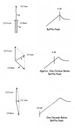
Yes. The problem is the magnitude of the front and rear phasors are equal, leading to deep nulls at zero frequency and at a number of comb frequencies above the dipole peak. I've made some crude sketches that show the vector relationships of an open baffle compared to a 6 dB resistive-mesh absorber.
The first (left) diagram shows the vector magnitudes as voltage relationships between the front and rear waves at a large distance (several meters) directly in front of the baffle. Notice the magnitudes are equal; the only thing that changes is the phase relationship. As the frequency moves downwards, the fixed transit delay from the center of the driver to the edge of the baffle becomes a smaller and smaller portion of the emitted wavelength. At very low frequencies, say, 1 decade below baffle peak, the front and rear waves are almost completely out of phase with each other, requiring substantial equalization if flat response is desired. In practice, diffraction attenuates the rear wave, but this is only significant at higher frequencies, primarily above baffle peak.
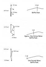
The second (center) diagram shows the vector magnitudes of a resistive mesh behind the driver, and for simplicity it is assumed that it has a frequency-independent loss of 6 dB. With practical acoustic absorbers, absorption is greatest at mid and high frequencies, and decreases at lower frequencies. Note that the deep nulls no longer occur, because the front and rear magnitudes are unequal, thus preventing total cancellation. The baffle peak is smaller as well, due to the decreased magnitude of the rear wave. In practice the baffle peak would be quite a bit smaller, possibly as small as 1 dB, because real-world absorbers have much better than 6 dB absorption from 500 Hz on up.
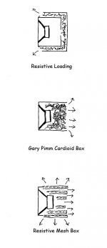
There is a continuum of possible ways to attenuate the rear wave, ranging from:
1) a totally absorbent infinite baffle (the classic mount-the-driver-in-a-door-to-another-room approach)
2) various types of resistive-vent boxes, such as the Dynaco A25 and the Planet10 Fonken
3) the Gary Pimm open-ended cardioid box
4) the proposed resistive mesh, a series of concentric mesh cylinders that are open at both ends and covered with thick felt
5) flat open baffles with no attenuation for the rear wave, ranging in size from large, door-sized panels to hanging the bare driver from strings
Sorry about the crudeness of the drawings and the math - I'm sure the figures are off, but the trends are there, and at the limit, this is how the systems behave with ideal drivers. Above the baffle peak the phasor for the rear wave spins around in the other direction, creating multiple 180-degree nulls and the comb filtering shown in Michael's simulations and measurements.
Attachments
Last edited:
- Home
- Loudspeakers
- Multi-Way
- Beyond the Ariel