Short story to the isobaric as it fits somehow.
When a friend got the new LINN Sara isobaric speaker at the time this product was new, we were invited to give that a listen.
The LINN Sara was a pretty compact two way speaker with two 10" and a dome IIRC.
Though the presentation was not that bad at all, especially with pretty amazing bass capability considering the relatively small footprint of that box, there always crept in a sonic pattern of low tuned beats.
Well I guess thats what Lynn described with the resonating part at low frequencies. There is energy interchange from the front to the back chassis and vice versa due to the separation by the air compliance that can be heard.
Besides that, one could also look at the sonic phenomena with isobaric principle from the viewpoint of "consecutively min phase behaviour" of course
Michael
Last edited:
Sheesh! I didn't think my casual remark about differential path lengths on an OB would re-ignite the minimum-phase war. I admit I use thought experiments on a lot of my thinking about speakers - I.E., if the baffle were 56 inches across, and an ideal (perfect) direct-radiator was in the exact center, an impulse from the rear of the cone would arrive 2 mSec later (at the listening position), and would of course be inverted. It would also be spectrally shifted (lowpassed) thanks to diffraction around the baffle edge.
Similar problems arise from reflections off the rear and side walls in box loudspeakers - but these have additional problems from standing waves as well. Sound absorption inside the box helps, but is far from complete absorption, so even an infinitely rigid box does store energy from repeated internal reflections.
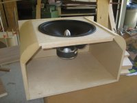
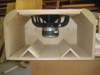
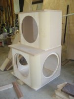
Changing gears, here's some photos from Gary Dahl. The slight inset on the front panel is room for the grille frame (something I won't be doing). The lower cabinet for the TD15H shows the left and right-side placement of the paired PR-700 passive radiators, along with the possible degree of offset for the TD15H required to keep an in-phase relationship on the 0.5 overlap portion of the crossover (the 200~300 Hz lowpass introduces a delay with respect to the TD15H wideband driver, and the exact amount of delay is not yet known).
Similar problems arise from reflections off the rear and side walls in box loudspeakers - but these have additional problems from standing waves as well. Sound absorption inside the box helps, but is far from complete absorption, so even an infinitely rigid box does store energy from repeated internal reflections.
Changing gears, here's some photos from Gary Dahl. The slight inset on the front panel is room for the grille frame (something I won't be doing). The lower cabinet for the TD15H shows the left and right-side placement of the paired PR-700 passive radiators, along with the possible degree of offset for the TD15H required to keep an in-phase relationship on the 0.5 overlap portion of the crossover (the 200~300 Hz lowpass introduces a delay with respect to the TD15H wideband driver, and the exact amount of delay is not yet known).
Attachments
Last edited:
Why not focus on why open baffles usually sound so damn good?
At least for bass?
No reason to feel bad - its not exactly the OB dipole principle that is under inspection / investigation here though it may sound like - its just that with OB dipole we have a very good "subject" for such a discussion .
*if* we finally could agree on the concept of "consecutively min phase behaviour" (to give that baby a name) quite any speaker design incorporating some dedicated delay is affected equally.
This includes horns (due to internal reflections or when back loaded) transmission lines, bass reflex, compound, and even a simple closed box speaker with theoretically perfect cavity absorption could bee in that group *if* a pronounced baffle step would be examined in that light.
Furthermore such point of view shades some additional light to DRC / digital room correction too - as this usually gets "only" damned for its 3-D dependency, though there is IMO a strong component of "consecutively min phase behaviour" issue in there as well.
So what looks as rather academic nitpicking discussion at a first glance may reach out pretty far...
Michael
Last edited:
No problem.
I was just curious.
And also wondering why everyone wants smaller baffles,
including using drivers in fee air without baffles at all.
To me the sound gets better with bigger/wider baffles.
Another thing, one of the things I really like about using open baffles for bass
is I can listen to music late at night without the neighbors hearing anything.
The technical bits of this thread sometimes goes over my head,
but I think it is very interesting none the less.
Hello Lynn and all, good to see this thread got back to life!
I was looking at the pictures posted and I see that there is a significant edge rising just before the rollovers. I guess the purpose is to have some kind of grills fixed on that edge.
Now, won't that edge effectively minimize the advantages of those nice, big roundovers? I mean, I almost can imagine diffraction occuring on that sharp termination
By the way, I like the project a lor, even if it's more conventional. I look forward to the outcome and to V2.
The way I see it's not an issue of "we". The concept as you want to describe it reduces to the description and math as John presented. As he's also pointed out in the past at least in other threads, it's easily verified empirically. At any point in space a raw measurement of a source with diffraction, be it closed box and baffle edge or dipole, will be minimum-phase. That of course is not by extension saying that the same result holds at all points, differing time delays and changing propagation dependent attenuation will alter it as well as driver directionality, as John pointed out. The fact is that at any of those other points, the combined response is still minimum phase. The question then changes to how does one take it all into consideration. Earl has his methods for his goals, others have theirs.*if* we finally could agree on the concept of "consecutively min phase behaviour" (to give that baby a name) quite any speaker design incorporating some dedicated delay is affected equally.
This includes horns (due to internal reflections or when back loaded) transmission lines, bass reflex, compound, and even a simple closed box speaker with theoretically perfect cavity absorption could bee in that group *if* a pronounced baffle step would be examined in that light.
Furthermore such point of view shades some additional light to DRC / digital room correction too - as this usually gets "only" damned for its 3-D dependency, though there is IMO a strong component of "consecutively min phase behaviour" issue in there as well.
So what looks as rather academic nitpicking discussion at a first glance may reach out pretty far...
Michael
All one need do is make a raw measurement at any point and create a sufficient and accurate model. The overlay of the HBT-generated phase and the measured phase demonstrates empirically that the response is minimum-phase. It should be clear that this cannot occur if the result is not minimum-phase.
One can conceptualize whatever one wants to try to present it, this changes nothing. There actually is no "doublet" or second impulse in reality, since diffraction of any baffle and more especially with any real non-point source driver is a distributed issue. The concept of "consecutively min phase behaviour" of which you speak might be a better way to describe it as it is the integrated response from the diffracting points. It looks neat and tidy in an impulse measurement, but that is of course just the way we tend to interpret or visualize it.
I can measure it at any point in space, model it to sufficient detail and create the HBT phase that nearly ideally overlays the measured phase when the excess-delay has been removed. That one must take the 4-pi issues mentioned previously as one factor of the designs doesn't change this aspect. It's just that, a design consideration.
Dave
Now, won't that edge effectively minimize the advantages of those nice, big roundovers? I mean, I almost can imagine diffraction occuring on that sharp termination
Hi SunRa,
Not sure exactly which edge you are referring to, so I will explain a bit more about the design.
The notches in the MDF corners are 3/4" deep. A front panel of 12 mm Baltic birch is set into these notches, leaving about 1/4" of remaining depth. The grill frames will be made from 1/4" fiberboard. When these are in place, their front surface will be flush with both the driver and the MDF corners. Neat, huh?
The panel has a 15.625" hole, about 1/16" larger than the woofer's frame. A second panel of 19 mm Baltic birch is glued behind the front panel, with a 14.125" hole. The woofer gets mounted to the inner panel.
You might have been referring to the corners of the top and bottom panels, which currently protrude beyond the rounded MDF corners. After they are all glued in place, I will trim them flush with the MDF corners with a router.
The side-mounted passive radiators won't have grill frames. They will be mounted to inner panels as well, set behind the 3/4" MDF side walls. This will leave the passive radiators approximately flush with the cabinet sides.
Next steps in construction will include installation of the remaining inner mounting panels for the drivers and more internal bracing. Then the tops will be glued on, and the corners of the tops and bottoms will be trimmed. After surface preparation is complete, the cabinets will be finished with black Duratex.
I'm busy this weekend conducting performances of Verdi's Luisa Miller for Puget Sound Opera, so I won't be in the shop again till Monday. Can't beat the sound of live music!
Gary Dahl
POST #1. "Boxes? We don't need no stink'n boxes.
POST #6500 "Boxes? We need boxes that don't stink."
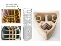
A 15" midrange with 70 grams Mms would seem to get optimal sound from a different cabinet than a more typical 6" midrange with 12 grams Mms. Some respected builders use a matrix of internal bracing, plus use dampening goop between two sheets of plywood for the cabinent sides construction. Some designers mimic B&W sphere + tapered tube in larger cabinets by putting a rapidly tapered transmission line behind the main cabinent volume.
Constructing and testing more than one midbass cabinet design might be worth the cost.
POST #6500 "Boxes? We need boxes that don't stink."
A 15" midrange with 70 grams Mms would seem to get optimal sound from a different cabinet than a more typical 6" midrange with 12 grams Mms. Some respected builders use a matrix of internal bracing, plus use dampening goop between two sheets of plywood for the cabinent sides construction. Some designers mimic B&W sphere + tapered tube in larger cabinets by putting a rapidly tapered transmission line behind the main cabinent volume.
Constructing and testing more than one midbass cabinet design might be worth the cost.
Attachments
It would be interesting to see what happens in reality.POST #1. "Boxes? We don't need no stink'n boxes.
POST #6500 "Boxes? We need boxes that don't stink."
...
Constructing and testing more than one midbass cabinet design might be worth the cost.
To simplify, there are 3 things that can potentially be issues with cabinets. Physical panel resonances, standing waves, and the direct reflection off the back of the cabinet back through the driver cone. The first thing is to properly brace the cabinet putting any physical resonance well above the intended range the cabinet will be used over. The closer the braces, the higher you push this resonance point in frequency. Secondly you want nonparallel surfaces and unequal distances to help avoid standing waves from developing. This can be as crazy as fully irregular walls to as simple as a brace at an angle behind the driver. The more irregular the better, however absorption inside the cabinet also helps to eliminate these issues. Finally you will want to redirect and or absorb any sound that may be coming from the back wave of the driver. Heavily packed insulation can do ok, but a soft polyurethane foam often works best for this.
John
John
I would like to know how the particular drivers were chosen.
Were they auditioned first or were the chosen based on TS parameters?
What about the Radian 745PB? Why not 850PB?
I am not criticising here, just want to know how you chose the drivers/horns.
Have you read through this thread?
I can tell you that the 745 vs. the 850 is down to horn size vs. low freq. extension. The larger the diameter of the compression driver, the larger the horn for the same low freq. extension. Simply put, the 745 enables the use of a smaller horn. The 745's exit diameter was also similar to another driver Lynn was interested in trying from Great Plains Audio. It's also similar to 18Sound's aluminum diaphragm driver. (..though the exit angle for each is different.)
The notches in the MDF corners are 3/4" deep. A front panel of 12 mm Baltic birch is set into these notches, leaving about 1/4" of remaining depth. The grill frames will be made from 1/4" fiberboard. When these are in place, their front surface will be flush with both the driver and the MDF corners. Neat, huh?
Gary Dahl
Huh! This is surprising! I was doing exactly this back in 1974 - for mid range drivers and tweeters, too - and I have been surprised that I have seen no manufacturer do the same.
This is the first reference I have seen to this little nicety in all these years.
Last edited:
To simplify, there are 3 things that can potentially be issues with cabinets.
Actually I have a thread on this..
http://www.diyaudio.com/forums/multi-way/80899-voodoo-vibration-loudspeakers.html
I'd also note that standing waves (or modes) in a cabinet requires that both the cabinet volume is relatively large AND that the driver is being used higher in freq. (..midrange). Though of course the 12M is being used in precisely this manner.
Have you read through this thread?
I can tell you that the 745 vs. the 850 is down to horn size vs. low freq. extension. The larger the diameter of the compression driver, the larger the horn for the same low freq. extension. Simply put, the 745 enables the use of a smaller horn. The 745's exit diameter was also similar to another driver Lynn was interested in trying from Great Plains Audio. It's also similar to 18Sound's aluminum diaphragm driver. (..though the exit angle for each is different.)
I have read about 100 pages so far, only another 560 to go.
Ok I have now discovered this has turned into a 3 way system.
What about 2 way or 2.5 way? Is this possible with the RAAL ribbons and the pro drivers mentioned so far?
Stuffing density distribution also makes a significant impact.To simplify, there are 3 things that can potentially be issues with cabinets. Physical panel resonances, standing waves, and the direct reflection off the back of the cabinet back through the driver cone. The first thing is to properly brace the cabinet putting any physical resonance well above the intended range the cabinet will be used over. The closer the braces, the higher you push this resonance point in frequency. Secondly you want nonparallel surfaces and unequal distances to help avoid standing waves from developing. This can be as crazy as fully irregular walls to as simple as a brace at an angle behind the driver. The more irregular the better, however absorption inside the cabinet also helps to eliminate these issues. Finally you will want to redirect and or absorb any sound that may be coming from the back wave of the driver. Heavily packed insulation can do ok, but a soft polyurethane foam often works best for this.
John
Stuffing density distribution also makes a significant impact.
I agree. I will be using Bonded Logic UltraTouch R-13. Some experimentation will most definitely be in order.
Gary Dahl
I agree. I will be using Bonded Logic UltraTouch R-13. Some experimentation will most definitely be in order.
Gary Dahl
One of the challenges is how far you can go with the top/bottom mode, which is the toughest to deal with in most constructions. With vented constructions the difficulty increases more because you can't overdamp the box volume and still have usable vent output (though I'd say that damped box tuning is an underused technique). I'm using a half-cylendar with those same "L" edge rounds (4" dia), and will have a stuffing chamber- about 4" of Ultratouch at the bottom, constrained between two shelf braces (with windows, roundovers on all exposed edges. I also used some layered materials to break up the surface of the top panel (as well as stiffen it) so I'm hopeful that I can leave the rest of the cab fairly minimally damped and keep that one significant mode suppressed. The rest of the cab is a 3/4" shell, with ribs of 3/4 stock, which are coupled to the shelf braces.
I'll try to get some pics up.
- Home
- Loudspeakers
- Multi-Way
- Beyond the Ariel