Hello,
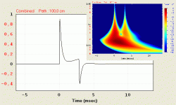
Here is (attached) the theorical impulse response of a subwoofer dipole calculated using Hornresp and its spectrogram (new feature added in Hornresp).
As we can see the impulse response due to the "back" wave arrives latter than the "front" wave. I really cannot see how a simple minphase equalisation will lead to a grouping of the 2 single pulses!
Best regards from Paris, France
Jean-Michel Le Cléac'h
Dipole response is minimum phase. Thus when a dipole response source is equalized, using minimum phase equalization, to the same band pass response as a direct radiator the impulse response is also the same.
Attachments
Thanks for the info, Lynn. Interesting concept.
Be sure to measure and don't count on that number. Some of the 416s fall out at about 94dB/W. They are very smooth on top, to be sure.
Widerange 15" driver - AESpeakers TD15M or Altec/GPA 416. Both drivers have similar efficiency (97~98 dB/metre)
Be sure to measure and don't count on that number. Some of the 416s fall out at about 94dB/W. They are very smooth on top, to be sure.
Hello,
Here is (attached) the theorical impulse response of a subwoofer dipole calculated using Hornresp and its spectrogram (new feature added in Hornresp).
As we can see the impulse response due to the "back" wave arrives latter than the "front" wave. I really cannot see how a simple minphase equalisation will lead to a grouping of the 2 single pulses!
Best regards from Paris, France
Jean-Michel Le Cléac'h
Jean-Michel
I can confirm that there are two distinct impulses to a dipole as thats what appears in the measurements of the Orion. But I don't see why this cannot be considered minimum-phase at LFs. The two distinct impulses, as you show them, are only visible as such because of the HFs. Remove them and the two "bumps" blur together into a single waveform that would be minimum-phase.
It's the diffraction that is almost always present in a dipole that is non-minimum phase. But there isn't much diffraction -per se - at LFs.
Last edited:
In the worst case with digital time-domain equalization, you'd get three signals arriving at the ear, the first arrival from the front of the driver, the delayed and inverted arrival from the back of the driver, and the mistimed digital correction signal.
Welcome to the reality of electronic EQ.
appealing concept: a closed box for a widerange bass driver ... and large-format horn have a conventional passive crossover, while the lower-efficiency ... has an active parametric EQ and power amplifier.
Where have I seen that before?
The two distinct impulses, as you show them, are only visible as such because of the HFs. Remove them and the two "bumps" blur together ...
As is nicely shown in the spectrogram that Jean-Michel provides. What would the section below ~300Hz look like if the reflection were removed? Much different?
J-M, can you run the sim again without the reflection so we can see the difference in the low end? It would be interesting to see what happens.
Thanks!
What "reflection"? There is one impulse from the front and another from the rear. But Jean-Michels impulses are idealized and could not be correct for a real system since each impulse would have to be a doublet and they would ring because of the HP characteristic. Filter out the highs and you just have two near sine waves that would blend together and become a single waveform without distinct peak arrivals.
Hello Panomaniac,
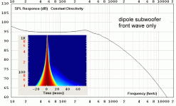
Here is the frequency response of the simulated subwoofer (actually this is an Infraplanar as the one used by Marco Henry in the to complement the 2010 version of La Grande castine) just using the front wave.
See attached file.
Best regards from Paris, France
Jean-Michel Le Cléac'h
Here is the frequency response of the simulated subwoofer (actually this is an Infraplanar as the one used by Marco Henry in the to complement the 2010 version of La Grande castine) just using the front wave.
See attached file.
Best regards from Paris, France
Jean-Michel Le Cléac'h
What would the section below ~300Hz look like if the reflection were removed?
J-M, can you run the sim again without the reflection so we can see the difference in the low end?
Attachments
Hello Earl,
Your explanation is OK for me as long as we don't ask the woofer to reproduce frequency at which the wavelength becomes short.
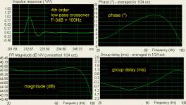
In order to see what happens at low frequency, I filtered the simulated Impuse response of the dipole (front + rear wave with a difference of path of 1 meter) using a 4th order low pass filter of the 4th order with F-3dB = 100Hz.
You'll see in attached file both, the shape of the pulse, the frequency response, the phase curve and the group delay curve (from ARTA).
Wish that measured real system could behave the same in the low frequency! (group delay variation lesser than time equiavalent to the difference of path between the rear and the front wave, very few phase variation, excellent frequency response.)
At very low frequency the wave drag along the baffle and turn around the baffle edge but from which frequency can we say that the rear wave of a dipole needs a reflection on a wall to interfer with the front wave...(if we consider the directivity of the piston, it should depend on the size of the OB I guess).
Best regards from Paris, France
Jean-Michel Le Cléac'h
P.S.: that dipole subwoofer is Claude Lacroix's Infraplanar.
What "reflection"? There is one impulse from the front and another from the rear. But Jean-Michels impulses are idealized and could not be correct for a real system since each impulse would have to be a doublet and they would ring because of the HP characteristic. Filter out the highs and you just have two near sine waves that would blend together and become a single waveform without distinct peak arrivals.
Attachments
I agree entirely. This thread was an opportunity for some of the greatest minds in our hobby to brainstorm, even if much like a brainstorming session it got off track sometimes and was hard to follow. There's lots of good info in here, even if it takes a couple days of reading to find it. Honestly, someone should take this offline someplace and index it for topics.
John
So how would you do that? I mean, can you download the entire thread at one time without going page by page using a screen capture program?
Thanks for the info, Lynn. Interesting concept.
Be sure to measure and don't count on that number. Some of the 416s fall out at about 94dB/W. They are very smooth on top, to be sure.
The only LF efficiency measure I trust is a direct measurement of the Thiele/Small parameters of the driver. If the Altec or GPA driver falls short (in BL product), back it goes.
The choice between the three compression drivers and two widerange drivers will amount to a subjective call; they fit similar mountings and all have pretty flat responses by the standards of the high-efficiency world.
I was looking at a printout of the JBL DD66000 crossover and was astounded to see the HF horn & compression driver had no less than three notch filters, as well as a shelf filter - this entirely aside from the DC-biasing technique JBL uses on their capacitors.
(The DC-bias technique doubles the numbers of caps, doubles their values since they are in series, and DC-polarizes the input/output pairs from a 9V battery distributing the polarizing voltage through an array of 1 megohm or so resistors. Add that to the notch filtering for the HF section and you have a pretty big crossover.)
My aim is for a simpler, more efficient (in the 97~100 dB/meter range) system with more moderate equalization requirements. As mentioned before, this isn't all that imaginative: studio monitors using pairs of 15" woofers in a 2.5 format have been around for a long time. The difference this time is we have more advanced BEM modeling for the horn (thank you Bjorn and JMMLC), as well as the latest drivers from AESpeakers. Compared to old-school studio monitors, that improves the time response and relaxes the equalization requirements, while retaining the high efficiency, high headroom, and low IM distortion.
Last edited:
I'm not going to spend much time on explaining this but here is an example. In the upper figure the double impulse is that of a dipole with 0.4msec separation along the dipole axis. The smooth impulse is what happens when the dipole on axis response is equalized to an acoustic band pass response consistent of a 100 Hz LR4 HP and 1k Hz LR4 LP filter. The lower figure overlays in green the impulse of the same electrical band pass filter. You can see the impulse for the band pass response is the same be it from the dipole system of the simple band pass filter.
The eq only applies on axis. As the reference point moved off axis the impulse will change in accordance to how the response changes. If it is a well designed dipole system the response will remain nominally the same with only reduce amplitude. On the other hand, if the response changes it will behave in accordance to those changes, just as a direct radiator system's impulse changes as the response changes off axis.
An externally hosted image should be here but it was not working when we last tested it.
The eq only applies on axis. As the reference point moved off axis the impulse will change in accordance to how the response changes. If it is a well designed dipole system the response will remain nominally the same with only reduce amplitude. On the other hand, if the response changes it will behave in accordance to those changes, just as a direct radiator system's impulse changes as the response changes off axis.
Hello,
Here is (attached) the theorical impulse response of a subwoofer dipole calculated using Hornresp and its spectrogram (new feature added in Hornresp).
As we can see the impulse response due to the "back" wave arrives latter than the "front" wave. I really cannot see how a simple minphase equalisation will lead to a grouping of the 2 single pulses!
Best regards from Paris, France
Jean-Michel Le Cléac'h
Work through the math! The double impulse response is minimum phase to start with.
Be sure to measure and don't count on that number. Some of the 416s fall out at about 94dB/W. They are very smooth on top, to be sure.
Then they aren't 416s.........
GM
Jean-Michel
It's the diffraction that is almost always present in a dipole that is non-minimum phase. But there isn't much diffraction -per se - at LFs.
Earl, don't bet the ranch that diffraction from a baffle edge when combined with the direct sound isn't minimum phase. The combined response, direct sound + diffraction genially results in a minimum phase response, be it a dipole system or direct radiator. Kates wrote a paper on this back in '77.
Last edited:
My aim is for a simpler, more efficient (in the 97~100 dB/meter range) system with more moderate equalization requirements. As mentioned before, this isn't all that imaginative: studio monitors using pairs of 15" woofers in a 2.5 format have been around for a long time. The difference this time is we have more advanced BEM modeling for the horn, as well as the latest drivers from AESpeakers. Compared to old-school studio monitors, that improves the time response and relaxes the equalization requirements, while retaining the high efficiency, high headroom, and low IM distortion.
Hi Lynn,
So, after researching dipole speakers for serveral years do you now believe that dipole home sound is inferior to monopole horns and woofers?
This sounds like a religious conversion! CONFESS!! ... what sins do dipole speakers commit?
In the upper figure the double impulse is that of a dipole with 0.4msec separation along the dipole axis.
Interesting example, but isn't that a rather short offset? 0.4mS would be a wavelength of what, about 5 1/2"? Circa 2500Hz. That's outside what you've filtered for.
Or am I missing something here?
Interesting example, but isn't that a rather short offset? 0.4mS would be a wavelength of what, about 5 1/2"? Circa 2500Hz. That's outside what you've filtered for.
Or am I missing something here?
It's called proper application of the dipole response. It is not really suitable to use a dipole response above the dipole peak and optimally it should be limited to about 1 octave below. Many designs, like the Orion and the NaO II do use the midrange to higher frequency but the driver directionality takes over so that above the dipole peak the response is not that of an ideal dipole. It is, however, still minimum phase.
Additionally, regardless of where I made the cut off for the simulation, the ideal dipole is minimum phase. The problem is the the ideal dipole can not be equalized flat because the nulls remain null regardless of how much eq is applied.
The underlying point is that if the response is minimum phase then minimum phase eq will correct both the amplitude and time response. So it becomes an issue only of whether the response can be eq'ed to the desired target with MP eq or not.
I discussed many of these issues here.
So how would you do that? I mean, can you download the entire thread at one time without going page by page using a screen capture program?
Hi John! All members with donation benefits (such as yourself) have access to the "Enhanced Thread Print" function. The details are on the donations page (diyAudio - Donations).
The Enhanced Print View was developed to meet the needs of diyAudio members who require more functionality than the standard vBulletin thread print offers, specifically the ability to easily print (long) threads, easily print threads with all images (such as schematics) and to save all the images in a thread to your computer.
It looks similar to the regular print view with the following differences:
* The number of posts on each page defaults to 100
* You have the option to view ALL posts on one page. This gives you the flexibility to use your browsers "print preview" and "print range" options to print a whole thread in one go, or any range of pages therein. It also lets you easily save all the images from a thread (see below).
* Attachments are resized to an 800 pixel wide "facade" by your browser so they look pleasant and are of manageable size while you browse, but print in full detail (as the original files are actually being linked/used)
* External images appear on the page instead of appearing as links
* Because all images appear on the one page, you can easily use DTA or Firefox (just go to [Tools]->[Page Info]->[Media] and use shift-click to "select all") to save all the images from a thread in one go.
Attachments
Sorry John, I'm being a bit thick here, but I still don't get it.
You have shown us 2 impulses that are 0.4ms apart. Sound would travel about 5.4" in that time. That's not much of a baffle, at least for bass.
What happens when you have impulses that are more in the range of 1-2ms apart and you are trying to use this in the mid bass? Such as a typical OB rig. Do these 2 impulses still blend together if low passed circa 200-400Hz?
- Home
- Loudspeakers
- Multi-Way
- Beyond the Ariel


