Klipsch sells replacement autoformers for a very modest price, something like US$25 or so. This is old information going back to the time when I was twiddling with the Klipsch Chorus loudspeakers - I also posted my results in more detail in the Klipsch forums, but that was something like four or five years ago. The performance of little Klipsch autoformers is excellent - the biggest downside is the taps are 3 dB apart, which is pretty wide spacing.
These days, I'd commission a special transformer from Bud Purvine or Dave Slagle, who both do terrific work that sounds first-rate. The transformer can be quite small, since they don't need to handle any current below 200 Hz, which in turn allows for a very small core size. As mentioned earlier, the turns ratio is the same the voltage ratio, and the impedance ratio is the square of the turns ratio.
The topology, which I think I've mentioned before, is like this:
Amplifier -> crossover -> 8 or 16-ohm shunt resistor -> primary -> secondary -> (optional Zobel inductance correction) -> compression driver.
This provides a load that is very close to resistive for the crossover network, and the compression driver sees a low source impedance both in the passband and in the band-reject region as well. Much better sounding than L-pad attenuation, since the impedance bumps are isolated from the crossover.
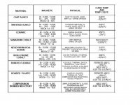
Keith Taylor said:Regarding magnet materials, Englishman John Watkinson has written on the subject in Electronics World magazine and in a more abreviated form at www.celticaudio.com/ Go to "technical articles" and read the last two paragraphs of the PDF called "putting the science back into loudspeakers" Mr Watkinson is no fool, being a fellow of the AES, the author of several books on digital audio and television and runs a company offering training in these and other subjects.
He seems to make a basic destinction between magnetic materials that are conductors and those that are insulators (ferrite) He suggests that in ferrites the magnetic domains move around when they are interacting with the coil flux and its attached load. This movement is not a linear process but rather is granular or noise like. The assumption seems to be that a ferrite magnet speaker is going to have noise sidebands associated with everything it reproduces. In the EW article he invited disbelievers to wrap some turns of wire around the ferrite magnet of a speaker being driven and look at/listen to the noise signal.
Keith
Well, there are parts of the article that are controversial, but I fully agree with his description of the sound of lossy codecs:
Even at high bit rates, corresponding to the smallest amount of compression, it was obvious that there was a difference between the original and the compressed result. The dominant sound sources were reproduced fairly accurately, but what was most striking was that the ambience and reverb between was virtually absent, making the decoded sound much drier than the original.
What was even more striking was that the same effect was apparent to the same extent with both MPEG layer 2 and Dolby AC-2 coders even though their internal workings is quite different. In retrospect this is less surprising because both are probably based on the same psychoacoustic masking model. MPEG-3 fared even worse because the bit rate is lower. Transient material had a peculiar effect whereby the ambience would come and go according to the entropy of the dominant source. A percussive note would narrow the sound stage and appear dry but afterwards the reverb level would come back up. An opportunity arose to compare the same commercially available recording on CD and MiniDisc and the MD version was obviously inferior. All of these effects largely disappeared when the signals to the speakers were added to make mono which removes the ear's ability to discriminate spatially.
The effects are not subtle and do not require "golden ears". We have successfully demonstrated these effects to an audience of about 60 in a conference room on more than one occasion; hardly the ideal listening environment, but all heard it. One of us (Watkinson) was asked in one demonstration if this was only relevant to classical recordings so the demonstration was repeated with a Bruce Springsteen recording and again all heard the difference.
We are forced to conclude that because of the phenomena described here, audio codecs have reached the market, which produce audible artifacts even at high bit rates, despite exhaustive subjective testing. When one examines the results of any subjective compression test, it becomes clear that the type of loudspeakers used would have been those having the shortcomings mentioned above. As a result these subjective tests are invalid because the masking of the legacy speakers was masking the coder being tested.
We must conclude that whilst compression may be adequate to deliver post produced audio to a consumer with mediocre loudspeakers, these results underline that it has no place in a quality production environment. When assessing codecs, loudspeakers having poor diffraction design will conceal artifacts. When mixing for a compressed delivery system, it will be necessary to include the codec in the monitor feeds so that the results can be compensated. Where high quality stereo is required, either full bit rate PCM or lossless (packing) techniques must be used.
This is exactly what I hear when I listen to lossy-compressed digital on the Ariels - a source-modulated ambient impression that shuts on and off, and is in general rather dry and "electronic" sounding. As the lossy compression is removed, and the bit depth increased from 16, up to 20, then up to 24 bits, the spatial impression becomes progressively more natural and less "processed" sounding. I also find that the quality of the amplification - in particular, use of Class A and subsequent freedom from switching artifacts - has a strong effect on the audibility of ambient impression. Class AB amplification, whether in op-amps (which is almost all of them), or power amplifiers, can quite noticeably degrade the realism of the spatial impression, regardless of loudspeaker.
These spatial effects are clearly audible in 2, 4, and 5-channel playback systems, although in multichannel systems, there are additional perceptual artifacts (from lossy compression) that translate into a sense of fatigue and a hard-to-describe unnatural quality. My experience with multichannel is that it requires higher standards (in the transmission channel, amplifiers, and loudspeakers) than 2-channel for long-term fatigue-free listening. This would mirror the experience with the mono-to-stereo conversion - stereo, to the surprise of its advocates in the late Fifties, turned out to require higher playback standards, and is a less forgiving system than mono.
As shown in earlier references, the Ariel was specifically designed to have a rapid time-decay signature, although it is not a "linear-phase" loudspeaker. My goals with the new speaker are similar, although I am now looking for a 10~15 dB increase in headroom. The challenge with multichannel is sufficiently great I am not addressing it at this time.
badman said:Indeed!
Or just to use quality AlNiCo drivers
The 12" Aquaplas JBLs had a lot going for them- some had very wide bandwidth and they all had monster motors to drive those heavy cones.
Just wonder if Alnico is the best place to spend the money on. What about cone design & material? SS uses slice paper cone. Seas uses some kind of coating - Nextel. What about Hemp cone on a good motor like lambda TD? Wouldn't this be a better cost vs benefit option?
Lynn Olson said:Much better sounding than L-pad attenuation, since the impedance bumps are isolated from the crossover.
I think that you have mentioned something about sidestepping an Lpad which is killing the amplifier damping factor in HF was another plus for using an autoformer. Do I remember well?
Alnico is worth the money - at least in the context of high-quality sources and amplification. It's not one of those silly "better-sounding-cables" distinctions - it's more like going from 16 to 20 bits, or a much-improved dither algorithm. For those of you into the triode scene, I find it comparable to the difference between a good-sounding 300B and an EL34 - it isn't all that subtle. For the digital cats, it sounds like the difference between UV22 dithering and primitive, undithered recordings. Or reducing jitter at the DAC chip. Less grain, more music, more vivid tone colors.
Now, as for field coils vs Alnico, I dunno. They sound different (I think) but it wasn't anything that jumped out at me. I'm not sure one is better than the other.
The sonic differences don't sound like a change in cone material, or suspension. It doesn't really sound like a speaker coloration in the usual way you'd expect. It sounds a lot more like improving the electronics, which is why I suspect it has something to do with the IM distortion spectra of the speaker in the region where VC inductance modulation is starting to make a difference. But that's only a guess. The studio-monitor pro world, though, has strongly favored Alnico when given a choice, and they are very familiar with the sound of different ADCs and DACs.
With compression drivers, there's a lot more controversy - and that could be because the pole pieces are already close to saturation anyway, and the type of magnet behind them is less significant.
SamL said:
Just wonder if Alnico is the best place to spend the money on. What about cone design & material? SS uses slice paper cone. Seas uses some kind of coating - Nextel. What about Hemp cone on a good motor like lambda TD? Wouldn't this be a better cost vs benefit option?
Considering the upper frequency response I wonder how much better the cone material can be on the TD drivers..............
I have heard both good and bad about hemp and that actually the real "pot" hemp is pretty crap for a speaker cone.
testing...
Not too long ago i had a couple pairs of 123a JBL woofers running full range in an OB. The high frequencies were AWFUL, but the midrange and lower midrange were amazing. Acoustic guitar and tenor sax never sounded so good.
I am thinking about picking up a pair of the TD15m to listen to full range in an OB. Although it is a low excursion driver, (as was the JBL), I think it will work well. Does anyone have an opinion on the overall sound quality...and the improvements acheived in utilizing the Apollo motor over the standard?
Best,
Chris
nickmckinney said:If you wanted Alnico it can be done but I imagine the price tag would be outrageous for 99% out there as you need a massive amount of steel to complete the circuit. Plus a large enough chunk of Alnico isn't cheap either.
Well I shall remove my foot from my mouth, I just learned its expensive but not really that expensive now thanks to the Chinese. Lemme start looking at what we can do..............
The first part of the "HowTo - as simple as it gets - for DIY CSD measurement" was about what CSD is good for and about some limitations applying.
It can be found here:
http://www.diyaudio.com/forums/showthread.php?postid=1505009#post1505009
All we need for really good CSD measurements is:
- a fairly sized room – no need for ceiling heights intended for giants nor for the Vatican
- no special dampening of that room – give the famous "pile of cushions trick" a try once you'd like to take a nap – not so much needed for the measurement itself
- a decent microphone at a decent stand – if you are in name dropping buy a Microtech Gefell or a B&K - if not, basically every brand (and unbranded) > € 150.- / electret / condenser will do – they will offer sufficient impulse response and FR – besides it can be equalised easily - isn't that important here (if you have skills - a € 5.- capsule will do – though I wouldn't recommend to go that path)
- a decent soundcard with mic inputs (24bit is a good idea though not really necessary) or a external mixer that offers an appropriate mic input. Most of the above mics do need phantom power.
- PC in an other room or relatively quiet notebook – no turbo booster rocket thing needed
- A power amp and some decent cables - nothing high-end needed here at all
- ARTA (free-) Software – there are others as well – no need to spend a fortune as processing of data is basically all the same – invented many, many years ago – some more options here some more beautiful colors there
- something – like a stool - to put your speaker on if you already have done the work out for your biceps this day
Well, the most crucial to me is a good mic-pre and a good mic if you have some extra bucks to spend. Up from the Behringer to the NTE and Earthworks M30. Some types do not need any phantom powered mic-in at all.
What I use? Almost all my measurements were taken with the Earthworks QTC1 attached to a standard mic stand and the Mackie Onyx 400F.
The big trick on CSD compared to other forms of measurement is that you truncate measured data.
As long as ONLY data is processed that has not been spoiled by room reflections you will obtain a very clean measurement of the speaker itself.
Obviously no other (strong) noise sources should be present as well. This isn't sooo hard to do, as CSD graphs are usually only down to –25dB – meaning, that your ambient noise level may be up to around 65dB in case you measure at 90dB (more quiet is better of course to have some margin left). That should be no problem measuring in the desert of Sahara or in the desert of NY
To calculate what is realistic in terms of data not spoiled by room reflections we take a look at the graph below.
Each hard boundary will create reflections of the original sound source – the speaker we'd like to measure.
Not shown in the picture – but equally important – are also the reflections coming from the floor and from the ceiling as well as from the wall behind the listener – the microphone in our case.
Whatever boundary creates the reflection "seen" first by the mic will be the limiting factor for the time we have received unspoiled sound from the speaker itself.
Obviously – if the room is large and the speaker AND the mic are far from any reflecting surface, we get unspoiled sound for a longer "time window" .
At domestic rooms you are usually limited by the ceiling height. If – for example – you place the speaker and the mic at a height half the room height, the reflections from ceiling and bottom will arrive at exactly the same time .
Now lets do a simple calculation and train the muscles between our ears:
For a ceiling height of 2,4m a maximum of 2,4[m]/330[m/sec] = 0,0072727272...sec = 7msec of reflection delay can be achieved.
From the speaker 1,2m up to the ceiling (OR down to the bottom) and 1,2m back to the mic – in our example - makes a 2,4m in total.
For a possible time window of 7msec in this example, your room has to be at least 2,4m high 2,4m wide, 2,4m deep AND you will have to place speaker and mic precisely in the center.
Usually we don't want to place the mic flush to the speaker so the reflection free "time window" is slightly lower (train your brain if you recall trigonometry from school) – but a 3msec to 5msec "time window" is always possible.
What about reflections of the mic stand?
Ever heard an beautiful echo in the mountains? - well its quite different from echos created by a forest at some distance.
But echo of a single tree I never have heard.
To be fair, there IS sound reflection at ANY hard surface – but geometry of that surface and the absolute reflecting area translated into a room section (Raumwinkel in German) seen by the mic together with frequency dependant diffraction don't leave too much to worry about.
Once you always see the same patterns at measurement of different speakers then it may be worth to explore – but until now – I had luck - and why shouldn't you?
to be continued....
Michael
It can be found here:
http://www.diyaudio.com/forums/showthread.php?postid=1505009#post1505009
All we need for really good CSD measurements is:
- a fairly sized room – no need for ceiling heights intended for giants nor for the Vatican
- no special dampening of that room – give the famous "pile of cushions trick" a try once you'd like to take a nap – not so much needed for the measurement itself
- a decent microphone at a decent stand – if you are in name dropping buy a Microtech Gefell or a B&K - if not, basically every brand (and unbranded) > € 150.- / electret / condenser will do – they will offer sufficient impulse response and FR – besides it can be equalised easily - isn't that important here (if you have skills - a € 5.- capsule will do – though I wouldn't recommend to go that path)
- a decent soundcard with mic inputs (24bit is a good idea though not really necessary) or a external mixer that offers an appropriate mic input. Most of the above mics do need phantom power.
- PC in an other room or relatively quiet notebook – no turbo booster rocket thing needed
- A power amp and some decent cables - nothing high-end needed here at all
- ARTA (free-) Software – there are others as well – no need to spend a fortune as processing of data is basically all the same – invented many, many years ago – some more options here some more beautiful colors there
- something – like a stool - to put your speaker on if you already have done the work out for your biceps this day
Well, the most crucial to me is a good mic-pre and a good mic if you have some extra bucks to spend. Up from the Behringer to the NTE and Earthworks M30. Some types do not need any phantom powered mic-in at all.
What I use? Almost all my measurements were taken with the Earthworks QTC1 attached to a standard mic stand and the Mackie Onyx 400F.
An externally hosted image should be here but it was not working when we last tested it.
The big trick on CSD compared to other forms of measurement is that you truncate measured data.
As long as ONLY data is processed that has not been spoiled by room reflections you will obtain a very clean measurement of the speaker itself.
Obviously no other (strong) noise sources should be present as well. This isn't sooo hard to do, as CSD graphs are usually only down to –25dB – meaning, that your ambient noise level may be up to around 65dB in case you measure at 90dB (more quiet is better of course to have some margin left). That should be no problem measuring in the desert of Sahara or in the desert of NY
To calculate what is realistic in terms of data not spoiled by room reflections we take a look at the graph below.
An externally hosted image should be here but it was not working when we last tested it.
Each hard boundary will create reflections of the original sound source – the speaker we'd like to measure.
Not shown in the picture – but equally important – are also the reflections coming from the floor and from the ceiling as well as from the wall behind the listener – the microphone in our case.
Whatever boundary creates the reflection "seen" first by the mic will be the limiting factor for the time we have received unspoiled sound from the speaker itself.
Obviously – if the room is large and the speaker AND the mic are far from any reflecting surface, we get unspoiled sound for a longer "time window" .
At domestic rooms you are usually limited by the ceiling height. If – for example – you place the speaker and the mic at a height half the room height, the reflections from ceiling and bottom will arrive at exactly the same time .
Now lets do a simple calculation and train the muscles between our ears:
For a ceiling height of 2,4m a maximum of 2,4[m]/330[m/sec] = 0,0072727272...sec = 7msec of reflection delay can be achieved.
From the speaker 1,2m up to the ceiling (OR down to the bottom) and 1,2m back to the mic – in our example - makes a 2,4m in total.
For a possible time window of 7msec in this example, your room has to be at least 2,4m high 2,4m wide, 2,4m deep AND you will have to place speaker and mic precisely in the center.
Usually we don't want to place the mic flush to the speaker so the reflection free "time window" is slightly lower (train your brain if you recall trigonometry from school) – but a 3msec to 5msec "time window" is always possible.
What about reflections of the mic stand?
Ever heard an beautiful echo in the mountains? - well its quite different from echos created by a forest at some distance.
But echo of a single tree I never have heard.
To be fair, there IS sound reflection at ANY hard surface – but geometry of that surface and the absolute reflecting area translated into a room section (Raumwinkel in German) seen by the mic together with frequency dependant diffraction don't leave too much to worry about.
Once you always see the same patterns at measurement of different speakers then it may be worth to explore – but until now – I had luck - and why shouldn't you?
to be continued....
Michael
SamL said:
Just wonder if Alnico is the best place to spend the money on. What about cone design & material? SS uses slice paper cone. Seas uses some kind of coating - Nextel. What about Hemp cone on a good motor like lambda TD? Wouldn't this be a better cost vs benefit option?
Well, Aquaplas is a pretty effective cone coating, for what they were trying to achieve. And "Spend the Money"..... the 123A (no doubt one of the easiest 12" to work with, with great bass, a strong motor, and a very well-behaved response profile ) is pretty darned affordable- you can get pairs for $125-$200.
The lambda drivers are gorgeous, and I'm considering ordering a few to play with.
SamL said:
Just wonder if Alnico is the best place to spend the money on. What about cone design & material? SS uses slice paper cone. Seas uses some kind of coating - Nextel. What about Hemp cone on a good motor like lambda TD? Wouldn't this be a better cost vs benefit option?
The benefit to the alnico is mentioned by a few others. It is less prone to the flux modulating as the coil moves through the gap. As Nick mentioned, the full copper sleeve on the pole achieves a similar effect. This shorts any eddy currents created by the coil's movement through the gap and as a result fixes the flux so it can't move. Whether it does it as well as alnico or not, we'll have to find out.
As far as cone materials go, there is a lot you can do once you pick a base material. The paper used in the TD drivers is fairly well behaved, but once the entire cone and surround is coated by hand spraying the coating on, it is extremely well damped.
Hemp as you know it is not hemp as most would think as Nick mentioned also. Charlie Barton went through numerous tests on the actual cannabis hemp as that is what they wanted to use. It just didn't have the right properties for a cone material. The hemp used now is manilla hemp which comes from a close relative to the Banana Tree. http://en.wikipedia.org/wiki/Manila_hemp It's the same paper used in the standard manilla envelopes with the little clasp on them. The hemp cone, while having good properties is more about having something unique to market than to have something really better. In reality it does some things better than traditional paper and some things worse. In the end it's just more different than anything.
I've had something in the works for a new cone material for quite some time now... That's for when I get some free time though.
")
John
mige0 said:
CSD is not just an other way to interpret a FR plot. CSD makes available additional information about what's happening when you want that driver to shut up.
This important piece of cake is not enclosed and cannot be derived mathematically from a FR measurement plot (though with some experience you may develop a subjectively "good guess" to extrapolate from FR to CSD).
No.
With the FR, you can derive the impulse and generate the corresponding CSD. The quality of the CSD depends on actual measurement. In theory there is no new information. FR/impulse are duals mathematically related and the CSD is just a chopped up impulse.
There is always more to be gained increasing the reflection free interval, i.e. improving the frequency resolution of the impulse. Slicing up and processing the impulse does not show any new information. In fact, because of the processing artifacts, it may show less accurate information. I occasionally still will run a CSD, but I regard them with suspiscion.
John_E_Janowitz said:The benefit to the alnico is mentioned by a few others. It is less prone to the flux modulating as the coil moves through the gap.
I've had something in the works for a new cone material for quite some time now... That's for when I get some free time though.
John
Hi John,
Have you done any work on wide bandwidth midranges? I think a wide 80-1,500Hz bandwidth 10" would mate well with Lynn's RAAL double high ribbons. When you look over magnetic properties, NdFeB looks very attractive for a 8-10mm underhung midrange motor with BL >17. The literature also has good data for paper cones with long Kevlar threads. Companies like 18 Sound have moved into these technologies for PAs, but do not look optimum for home use.
Any data on your new midranges? Maybe a 10" with an extended Xmax version of the TD15M underhung motor using NdFeB on a 10 super cone.
Attachments
John_E_Janowitz said:The hemp used now is manilla hemp which comes from a close relative to the Banana Tree.
Manilla has no relation to hemp except that after the US govt made hemp illegal, they promoted manilla as a replacement and started calling it manilla hemp to put an exclamation mark to the scheme. If what John is saying is true, then calling them hempcones is a buig misnomer.
It should be possible to make a very good cone if one chose the right strain of hemp... it can be used to make all sorts of grades of paper, rope, and cloth that ranges from canvas to silk-like.
dave
ucla88 said:
No.
With the FR, you can derive the impulse and generate the corresponding CSD. The quality of the CSD depends on actual measurement. In theory there is no new information. FR/impulse are duals mathematically related and the CSD is just a chopped up impulse.
I am afraid I must respectfully disagree. You are making an implicit assumption that all loudspeaker systems are minimum-phase.
Most multiway systems are not - the crossovers act as allpass filters. An allpass (phase-rotating) filter has a completely flat frequency response, and will measure as such on a display that discards time information - which the standard FR graph does. Traditional techniques such as swept-sinewave, or filter-bank Real Time Analyzers, do not collect time or phase information, and will also be incapable of distinguishing an allpass characteristic from a straight wire.
In addition to allpass crossovers, very few multiway systems have time-coincident driver alignments. It is more convenient and esthetically attractive to mount all of the driver flanges on a common front panel, and let the time arrivals fall where they may. Here is an especially dramatic example from a 3-way horn system, showing the frequency response:
Attachments
And here is the impulse response (which was used to calculate the frequency response shown in the previous post).
This loudspeaker is grossly non-minimum phase, with the tweeter several wavelengths ahead of the mid-horn. The front flanges of the horns are all nice and pretty on the front panel, but the diaphragms are several inches apart - and the crossover is at 6.2 kHz.
The frequency response shows a deep notch, but how can the impulse be calculated from a display with no time or phase information, and both the crossover and driver alignments are non-minimum phase?
There are many different locations in space that would produce the notch shown in the previous post. With time or phase information preserved (and collected in the first place by the appropriate measurement technique), the impulse response, deviation from minimum-phase, and CSD can all be shown. If the time and phase information were never collected in the first place, they cannot be re-created.
Loudspeakers are not amplifiers. They are more akin to an RF transmission path with severe multipath problems, and the associated degradation of time-dependent signals such as stereo FM, NTSC and PAL color television, and PCM. What makes the problem more challenging than the RF equivalent is the extreme bandwidth required - two to three decades, an astounding bandwidth in the RF world - and the complex radiation pattern of the emission source, which shows an additional non-minimum phase characteristic that changes with emission angle.
Attachments
There's a little story I heard a long time ago. Los Angeles, home of Altec and JBL, was deeply resistant to time-based measurement methodologies. It was swept-sinewave or nothing for these guys.
Just to stir things up, Richard Heyser sprang a little surprise at a Los Angeles AES meeting. It was a little black box that had very low distortion, measured completely flat using Altec and JBL's swept-sinewave methodologies, yet was so grossly distorted that speech was unlistenable. Much head-scratching ensued - and Dick already had a well-established reputation as one of those Caltech wise guys.
At the end of the talk, he revealed the secret of the black box: it was a very high-order allpass filter, that was randomly switched in and out of the signal path. It completely garbled the time domain in the fashion of an especially bad shortwave signal.
This is one of those apocryphal stories I heard back when I lived in The City of the Angels, but I knew several Caltech guys, and it sure sounded in character to me - they were always up to some kind of complex intellectual stunt.
I look back at the numerous articles Richard Heyser published in Audio magazine in the early Seventies, and the resounding silence that greeted them from Altec and JBL. No time domain for us, no sir! There's some irony in the fact that both companies were turning their back on the (time-aligned) Shearer Theater Horn that they owed their existence to.
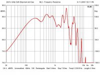
Zilch over at the Lansing Heritage Forum has made a set of measurements of JBL 123A, as used in the L100 "Century". Scroll down to Post #52 to see Zilch's graph of the midrange, reproduced below.
I think "heavy equalization" is the right word here. If this driver were to be used in a high-fidelity application, it's going to have to be aggressively lowpassed with a 24 dB/octave filter, massive notch-filtering, or both.
Since the JBL L100 "crossover" did not use any lowpass filter at all for the 123A, you can see what kind of midrange this speaker had - designed to mimic the peaks of the Altec 604 Duplex. Yes, the peaking was intentional, and just the kind of boom-and-sizzle the target market wanted. JBL sold a zillion of these things - that Maxell ad with the flying cocktail glass put the L100 on the map for all time. I have to admit the L100 has always looked great, with that beautiful white cone and the cool 3D-effect grill foam in electric blue or that true 70's color, funkadelic burnt-orange.
Attachments
- Home
- Loudspeakers
- Multi-Way
- Beyond the Ariel