Charles Hansen said:in my estimation the TADs are overall better than the K2's. But if you didn't like the TADs, I'm not sure you will like the K2's any better.
The TAD 1 plywood ribs screw_rods + glue stack-up showing extensive bracing and box resonance control.
Attachments
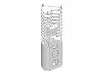
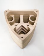
LineSource said:The TAD 1 plywood ribs screw_rods + glue stack-up showing extensive bracing and box resonance control.
Also, be aware that the "box resonance control" you are talking about is not the same issue that Lynn brought up in his post.
Re: Re: Measurements, and PHL 1120 as a midrange
Thanks for that. What puzzels me is that quite a few seem to like and praise the PHL 1120 (Aleksandar from RAAL, Nelson Pass) despite what looks (to me at least) as irreparable cone breakup around 3k.
Regarding measurements, the first one posted seems to be the standard 1m measurements whereas the one I posted is taken in nearfield at 1''.
However, things seem to correlate: In the second graph there there is a glitch in the impedance response at the same point
How does that cone breakup sound when the PHL is XOed (4th order LR, as most seem to do) at 2.5k would be very intresting to hear (with no tweet).
Thanks for the link,
Florian
P.S. The Audax seems not much better either. Take a look at the CSD: http://www.cadaudio.dk/pr170m0.pdf
SamL said:
http://www.diyaudio.com/forums/showthread.php?s=&threadid=6363&highlight=
Old post with brief comment on PHL1120, more on Audax PR170M0.
Thanks for that. What puzzels me is that quite a few seem to like and praise the PHL 1120 (Aleksandar from RAAL, Nelson Pass) despite what looks (to me at least) as irreparable cone breakup around 3k.
Regarding measurements, the first one posted seems to be the standard 1m measurements whereas the one I posted is taken in nearfield at 1''.
However, things seem to correlate: In the second graph there there is a glitch in the impedance response at the same point
How does that cone breakup sound when the PHL is XOed (4th order LR, as most seem to do) at 2.5k would be very intresting to hear (with no tweet).
Thanks for the link,
Florian
P.S. The Audax seems not much better either. Take a look at the CSD: http://www.cadaudio.dk/pr170m0.pdf
Yes, the "box modes" I was speaking of would occur in an infinitely rigid box - think of it as room modes writ small, or rather, happening at frequencies about ten times higher. Unlike room modes, though, these standing waves compete with the characteristic sounds of wood-box instruments, such as violins, cellos, and pianos. They screw up the timbre of these instruments and add an unnatural - well, "boxy" sound to vocals.
This particular coloration tends to go unnoticed since it is so common - it's the generic sound of table radios, TV sets, just about everything. Audiophiles put up with the problems of electrostats and magnetic-planars just to get away from the annoying box sound - but then accept serious dynamic-range restrictions "as the price they must pay" to avoid box colorations. This choose-one-or-the-other dichotomy, which has existed since the days of the Quad ESL57 and the KLH 9, has bedeviled the audio community for decades.
High-efficiency dipoles can offer a way out. There are still plenty of challenges - increasing dynamic range in the bass is the most obvious one - but it is an alternative that bridges the gap between electrostats and large-format studio monitors. You have to give up the idea of a compact little speaker that is apartment-friendly, but you have to do that anyway if you want wide-range dynamics. As the designer of one of these cute little speakers, I am all too aware of the dynamic-range restrictions of this genre of loudspeaker.
Aside from decor-friendliness, one of the technical advantages of mini-monitors (or nearfield monitors, take your pick) is a box size where the colorations occur at a higher frequency than the traditional studio monitor - and at frequencies where box linings actually start to work successfully. Thus, the "crisper" sound of the little monitors.
The B&W Nautilus was a clever attempt to control the box modes by forcing the backwave into lossy tapered transmission lines, but then problems with resonant modes in large areas of fiberglass arise - no free lunch here either. And don't believe all you read about magical damping properties of this or that damping goo, damping pads, this that or the other - getting just a few dB of attenuation out of these magic materials is a big challenge.
The proof, as always, is in the measurements and listening. The trick with measurements, of course, is getting some degree of correlation with what you hear - and what to listen for.
Charles Hansen said:
All I can tell you is that CSD (waterfall plots) are not a very good way to examine the behavior of the diaphragm. They will show very gross problems, but are completely unable to show more subtle problems.
Well all too true.
My point on this one simply is that speaker industry first has to solve the gross problems - like cone breake up and fast decay over a wide frequency range - all too visible at CSD's.
- no need for DOS based MLSSA since there is the user friendly ARTA - thought you still have to accept the 1/12 octave smoothing in the current (freeware) version.
- no need for big rooms
- no need for long windows
- no need for anechoic rooms
- no need for outdoor measurement.
(True only for the range of 300Hz up of course)
Why doesn't it spread more?
Well speaker industry isn't really interested in pictures where "Mr Anybody" can point with the finger on gross defects.
But why don't we see it more in the DIY community? Use the DiyAudio search engine and type in CSD - you get barley 1000 hits .
Even worse - out of that 1000 most are just talking – no "hard data" .
It's simply because there still is that nimbus on that it is sooo complicated to do and sooo complicated to interpret.
- no – it is NOT
At least for breake up resonances (and some other defects) applies: "If it walks like a duck and quacks like a duck, then it is a duck."
")
Only ONE single page on the whole www I am aware of that consequently displays CSD: ZaphAudio
WHAT a PITY
Lynn Olson said:
The proof, as always, is in the measurements and listening. The trick with measurements, of course, is getting some degree of correlation with what you hear - and what to listen for.
All too true.
- no need to produce "perfect" measurements – ist's just a waste of time and you NEVER ever will succeed no matter on how high tech equippment you use – the best measurement one can do are the one's that serves the process of learning – individually or collectively.
Greetings
Michael
Lynn Olson said:
The B&W Nautilus was a clever attempt to control the box modes by forcing the backwave into lossy tapered transmission lines, but then problems with resonant modes in large areas of fiberglass arise - no free lunch here either. And don't believe all you read about magical damping properties of this or that damping goo, damping pads, this that or the other - getting just a few dB of attenuation out of these magic materials is a big challenge.
From some own measurements I can tell there is VERY little effect on the concept of the Nautilus box shape concerning dampening modes – I doubt it can be called a (lossy) transmission line concept at all.
No DIY projects I am aware of that report / verify a break through.
Well its beautiful and at least an outstanding design – and CLEVER marketing of course.
Greetings
Michael
Lynn Olson said:By the way, I'd like to thank John Janowitz for the information and graphs on the AE Speaker Lambda TD-15M. That certainly look like a contender - let me know if you're considering Alnico, that would make it even more attractive, and would justify a higher price. (I can't believe I just said that!)
In my experience, Alnico isn't so much about adding a guitar-friendly coloration, but more about noticeably better rendition of instrumental subtleties and a more palpable, in-the-room quality to the instruments - a palm sliding across the surface of a drum, the sound of wood in the cello, more vivid tone colors that sound less artificial and more real. The difference is most apparent in the 200 to 1 kHz region, from what I heard.
In the amplifier world, this isn't a clever type of coloration you can add, but more a matter of reduction of distortion, or an improvement in a power supply. Alnico does something better, and I don't know what it is, although my guess is something to do with back-EMF's induced in the magnet structure. It does sound very much like better core materials in audio transformers, for those of you who have auditioned different transformers.
I looked at Alnico sometime back and learned that the thick copper tube I used in the TD driver design acted alot like Alnico did. Alnico from what I remember kept the inductance lower and also didn't allow the stationary gap flux to be moved by the "temporary" magnetism of the voice coil. Its been years and I forget many of the details for this. We even looked at testing a field coil version as that is supposedly the best magnetic field that can be made.
If you wanted Alnico it can be done but I imagine the price tag would be outrageous for 99% out there as you need a massive amount of steel to complete the circuit. Plus a large enough chunk of Alnico isn't cheap either.
Nick McKinney
(he's back)
nickmckinney said:Nick McKinney
(he's back)
Welcome back, Nick!
I never got a chance to thank you for those wonderful drivers you made for me a few years ago - so... Thanks!
Hope you enjoy your stay!
http://www.audioroundtable.com/ProSpeakers/messages/50.html
From an old post on alnico and ferrite magnet by JBL.
"Here is an interesting document written by John Eargle that compares various magnet structures and what performance can be expected from them. A horn provides 10dB to 15dB gain and a similar reduction in distortion. But the geometry of the driver's magnetic flux can do that much or more where distortion is concerned.
Three magnetic structures are compared, each having physical symmetry, but each made with a different material or technology. One is an alnico magnet, the other a ferrite and the third is a ferrite magnet with a flux stabilization ring........."
Oh yes! Good to hear from you again Nick.
Take that JBL structure, extend the pole outward about an inch, then cover it with a thick layer of copper so that no matter where the voice coil is located the copper is right next to it. Then you have a TD motor. The JBL ring is a good low cost design, but it doesn't address the inductance and phase response of the driver, nor does it help with heat sinking and power compression.
Regarding magnet materials, Englishman John Watkinson has written on the subject in Electronics World magazine and in a more abreviated form at www.celticaudio.com/ Go to "technical articles" and read the last two paragraphs of the PDF called "putting the science back into loudspeakers" Mr Watkinson is no fool, being a fellow of the AES, the author of several books on digital audio and television and runs a company offering training in these and other subjects.
He seems to make a basic destinction between magnetic materials that are conductors and those that are insulators (ferrite) He suggests that in ferrites the magnetic domains move around when they are interacting with the coil flux and its attached load. This movement is not a linear process but rather is granular or noise like. The assumption seems to be that a ferrite magnet speaker is going to have noise sidebands associated with everything it reproduces. In the EW article he invited disbelievers to wrap some turns of wire around the ferrite magnet of a speaker being driven and look at/listen to the noise signal.
Keith
Keith Taylor said:Regarding magnet materials, Englishman John Watkinson has written on the subject in Electronics World magazine and in a more abreviated form at www.celticaudio.com/ Go to "technical articles" and read the last two paragraphs of the PDF called "putting the science back into loudspeakers" Mr Watkinson is no fool, being a fellow of the AES, the author of several books on digital audio and television and runs a company offering training in these and other subjects.
He seems to make a basic destinction between magnetic materials that are conductors and those that are insulators (ferrite) He suggests that in ferrites the magnetic domains move around when they are interacting with the coil flux and its attached load. This movement is not a linear process but rather is granular or noise like. The assumption seems to be that a ferrite magnet speaker is going to have noise sidebands associated with everything it reproduces. In the EW article he invited disbelievers to wrap some turns of wire around the ferrite magnet of a speaker being driven and look at/listen to the noise signal.
Keith
Thats why you need a giant piece of solid copper intersecting as much of the flux field as possible.
Take that JBL structure, extend the pole outward about an inch, then cover it with a thick layer of copper so that no matter where the voice coil is located the copper is right next to it. Then you have a TD motor. The JBL ring is a good low cost design, but it doesn't address the inductance and phase response of the driver, nor does it help with heat sinking and power compression.
He seems to make a basic destinction between magnetic materials that are conductors and those that are insulators (ferrite) He suggests that in ferrites the magnetic domains move around when they are interacting with the coil flux and its attached load. This movement is not a linear process but rather is granular or noise like. The assumption seems to be that a ferrite magnet speaker is going to have noise sidebands associated with everything it reproduces. In the EW article he invited disbelievers to wrap some turns of wire around the ferrite magnet of a speaker being driven and look at/listen to the noise signal.
Thanks for your comments. Most interesting! Where would you place neodymium magnets in this discussion?
Maybe one should put together a HowTo - as simple as it gets - for DIY CSD measurement.
Why do we need that CSD at all?
CSD is not just an other way to interpret a FR plot. CSD makes available additional information about what's happening when you want that driver to shut up.
This important piece of cake is not enclosed and cannot be derived mathematically from a FR measurement plot (though with some experience you may develop a subjectively "good guess" to extrapolate from FR to CSD).
Good thing is - CSD's are easy and intuitively to "read" and nowadays - thanks to the Hungarian guys of ARTA – headache free to catch.
To get 90% of what CSD can tell you, the requirements in terms of time, investment and specialised knowledge are amazingly low.
In the context of this thread its even easier, as we really don't need CSD examination beyond around 300Hz.
This roughly 300Hz cut off is one hard limitation to allow measurement even in relatively small rooms.
Easy to accept for OB designs - where 99,9% of all speakers show the same and easy predictable behaviour of piston movement and no box decay has to be chased.
An other hard limitation you have to accept is, that this CSD's are ONLY good to tell you about the decay time behaviour of a speaker.
Its way more difficult to get a 90% informative frequency response measurement than a 90% informative CSD measurement
If you are that kind of measurement perfectionist that wants to show around brilliant, academic level graphs – stay away – buy sunglasses of RayBan or Boss - invest a smaller or bigger fortune on equippment, a looooot of time to wrap your head around – and come back once you realise that you got a brilliant 93% of what's in the pot.
Of course a CSD measurement shows the frequency response as well. This is basically the Z-direction (height at the very beginning of the decay-timeline) – but this is not what we are interested in here nor do we make any effort to get that aspect somewhere close to perfect.
The main focus of CSD is what's happening along the Y-direction, the decay-timeline over the frequency band.
Frequency response and CSD are not that closely bound to each other than FR and phase for example is.
To stay correct – both FR and CSD measurements have its roots in the impulse response. Unfortunately impulse response graphs don't make sense to most of us – they are really hard to decipher in detail - though it basically contains ALL the data we can extract from a speaker (well, obviously you wont get the spider diameter nor the smell of the cone material ).
to be continued....
Michael
PS :
to correct a gross mistake at my last posting:
one more – excellent - page about CSD is from the '"owner" of this thread.
http://www.nutshellhifi.com/MLS/index.html
PPS :
an other page that I came across some time ago and forgot about - with lots of CSD data I'd like to make available, is from the French guys. Its focused on Audax speakers only, but almost the complete range from way back.
http://www.hautparleur.fr/
PPPS :
a page I recommended earlier is from the Czech guys at ProDance with some of the newer PRO-speakers having CSD graphs
http://www.prodance.cz/protokoly.php?AnchorID=49&Lng=CZ
Why do we need that CSD at all?
CSD is not just an other way to interpret a FR plot. CSD makes available additional information about what's happening when you want that driver to shut up.
This important piece of cake is not enclosed and cannot be derived mathematically from a FR measurement plot (though with some experience you may develop a subjectively "good guess" to extrapolate from FR to CSD).
Good thing is - CSD's are easy and intuitively to "read" and nowadays - thanks to the Hungarian guys of ARTA – headache free to catch.
An externally hosted image should be here but it was not working when we last tested it.
To get 90% of what CSD can tell you, the requirements in terms of time, investment and specialised knowledge are amazingly low.
In the context of this thread its even easier, as we really don't need CSD examination beyond around 300Hz.
An externally hosted image should be here but it was not working when we last tested it.
This roughly 300Hz cut off is one hard limitation to allow measurement even in relatively small rooms.
Easy to accept for OB designs - where 99,9% of all speakers show the same and easy predictable behaviour of piston movement and no box decay has to be chased.
An other hard limitation you have to accept is, that this CSD's are ONLY good to tell you about the decay time behaviour of a speaker.
Its way more difficult to get a 90% informative frequency response measurement than a 90% informative CSD measurement
If you are that kind of measurement perfectionist that wants to show around brilliant, academic level graphs – stay away – buy sunglasses of RayBan or Boss - invest a smaller or bigger fortune on equippment, a looooot of time to wrap your head around – and come back once you realise that you got a brilliant 93% of what's in the pot.
An externally hosted image should be here but it was not working when we last tested it.
Of course a CSD measurement shows the frequency response as well. This is basically the Z-direction (height at the very beginning of the decay-timeline) – but this is not what we are interested in here nor do we make any effort to get that aspect somewhere close to perfect.
An externally hosted image should be here but it was not working when we last tested it.
The main focus of CSD is what's happening along the Y-direction, the decay-timeline over the frequency band.
Frequency response and CSD are not that closely bound to each other than FR and phase for example is.
To stay correct – both FR and CSD measurements have its roots in the impulse response. Unfortunately impulse response graphs don't make sense to most of us – they are really hard to decipher in detail - though it basically contains ALL the data we can extract from a speaker (well, obviously you wont get the spider diameter nor the smell of the cone material ).
to be continued....
Michael
PS :
to correct a gross mistake at my last posting:
one more – excellent - page about CSD is from the '"owner" of this thread.
http://www.nutshellhifi.com/MLS/index.html
PPS :
an other page that I came across some time ago and forgot about - with lots of CSD data I'd like to make available, is from the French guys. Its focused on Audax speakers only, but almost the complete range from way back.
http://www.hautparleur.fr/
PPPS :
a page I recommended earlier is from the Czech guys at ProDance with some of the newer PRO-speakers having CSD graphs
http://www.prodance.cz/protokoly.php?AnchorID=49&Lng=CZ
Neo magnet material is some of the best man has ever invented. Its only problem is that it doesn't like to be any thicker than about a 1/4" which sucks for woofer duty unless you place it sideways like the Aura stuff did. Its other problem is that you need one hell of a magnet charger..............
- Home
- Loudspeakers
- Multi-Way
- Beyond the Ariel