Re: Multiple tweeters
The Dynaudio Confidence C4 uses 2 tweeters in a vertical configuration. I notice that they are spread about 2-3 inches apart. I assume to reduce the comb filtering effect. Generally most piezo tweeters sound bad. Also tweeters are usually more efficient that other non pro drivers so you don't need any extra ones when using dome tweeters as they have wide dispersion.
dobias said:Gentlemen,
Would someone either point me to a thread about multiple tweeters or provide an answer as to why I don't see more speaker systems with mutiple tweeters.
With the beaming of tweeters as a problem, I wonder why Bozak's solution hasn't been used more. The least he used was a pair of tweeters on about a 15 degree spread to either side of center. I always considered his bank of tweeters assembled in a hemispherical array as a grand, if not grandiose, solution.
I find that a second tweeter facing away from the listener
(bipolar?) helps to fill in the upper register.
With the availability of low cost piezo tweeters, would an array be worth trying or would the sound quality suffer?
dobias
The Dynaudio Confidence C4 uses 2 tweeters in a vertical configuration. I notice that they are spread about 2-3 inches apart. I assume to reduce the comb filtering effect. Generally most piezo tweeters sound bad. Also tweeters are usually more efficient that other non pro drivers so you don't need any extra ones when using dome tweeters as they have wide dispersion.
A long time ago, the second speaker I designed for Audionics used a pair of Peerless HFC-225 cone tweeters in a short vertical array. Normally, tweeter arrays are a Bad Thing, but the fairly large cone area of the HFC-225 made it behave a little more like a single vertical strip. Vertical dispersion was pretty narrow, as I recall - maybe a foot high at the listening position. Pointing the speaker right at the listening area was a good idea, otherwise it sounded kind of muffled.
I still have a soft spot for cone tweeters compared to domes; they have a gentler, more natural sound, and are free of the spit, sizzle, and upper-midrange "chrome-plated" effect of many domes. Looking back, I suspect the Peerless HFC-225's were based on the Bozak predecessor, with a 2" paper cone with a 1/2" nearly-flat aluminum dustcap in the center. Very nice sound indeed, limited only by rather modest power-handling and low efficiency (something like 84 dB/metre), thus the requirement to use them in pairs. In my experience, multiple dome tweeters sound kind of nasty - the annoying dome upper-mid colorations are still there, combined with a new, blurry, out-of-focus coloration (which I didn't hear with the Peerless cone-tweeter arrays).
The big problem with any array of drivers is non-coincident arrival times. This is not so important in the bass region, where wavelengths are long and floor and wall reflections merge with the direct-arrival wave. But at higher frequencies (say above 500 Hz) coincident arrival becomes more important, and becomes very important above 3 kHz, where multiple arrivals (multipath) have effects similar to severe diffaction. In subjective terms, image quality is diffused, front-to-back depth is shortened or eliminated altogether, and "phasey" colorations become audible with vocals and massed choirs. Chasing this coloration out of the MTM Ariel was a very tedious business, requiring offset drivers, large-radius corners, and a lot of phase-trimming in the crossover.
A quick way to test for coherence is listen to clicks and pink-noise, and compare by direct switching to a single-driver loudspeaker (quality of the single driver is not important for this test). If you hear blurred clicks or "phasey" pink-noise, the multi-driver system has problems with non-coincident arrival times. This is a very common defect, especially in audiophile boutique systems with large arrays of drivers and price ranges in the Porsche and Ferrari region.
Getting good treble with large dynamics and good (coherent) time response is not trivial.
Re: 26
25
Like a wise man once said, it's not the size that matter mate
25
Like a wise man once said, it's not the size that matter mate
It will probably be bigger than domestically acceptable (to me) but certainly worth a listen once completed.
C [/B]
Other baffle designs
Since there is not too much action with this thread, I will direct people to another thread. JohninCR posted some time ago that he has been experimenting with different baffle designs. This thread summarizes some of his work and some initial impressions. If you remember, one of his very inovatiive designs was a waveguide baffle with rounded edges to deal with edge diffraction. If you have time to burn read this:
http://www.audiocircle.com/circles/index.php?topic=36862.0
Retsel
Gradient Helsinki 1.5
Here is a new design from Gradient
http://www.gradient.fi/helsinki15/
Not very much information has been posted yet. While they don't have a manual posted yet, I'm wondering how it is supposed to be placed in the room for the side mounted woofer to function as a dipole. Could it be that it is supposed to be placed at a 45 degree angle to the rear wall?
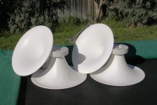
It looks like a waveguide mounted SEAS metal dome tweeter, a side-mounted 15" woofer, and a 6.5-8" midrange mounted in some type of diffuser. I'd like to hear more about it if anyone sees it at CES 2008.
Here is a new design from Gradient
http://www.gradient.fi/helsinki15/
Not very much information has been posted yet. While they don't have a manual posted yet, I'm wondering how it is supposed to be placed in the room for the side mounted woofer to function as a dipole. Could it be that it is supposed to be placed at a 45 degree angle to the rear wall?
It looks like a waveguide mounted SEAS metal dome tweeter, a side-mounted 15" woofer, and a 6.5-8" midrange mounted in some type of diffuser. I'd like to hear more about it if anyone sees it at CES 2008.
Attachments
Re: Gradient Helsinki 1.5
If I remember correctly it isn't a dipole at higher freq.s - its a cardioid configuration similar to the midrange driver. Basically the woofer "baffle" is not a slab of wood, but rather is hollow slat with the "opening" at the rear. The woofer's magnet I believe visibly protrudes on the other side like a ripole (..but of course is sealed to the "cabinet" to prevent air leakage from that that area - instead only allowing it to "leak" from the narrow vent in the rear). If it actually is a dipole at higher freq.s (but still constructed as I've mentioned), then that slot will likely impart a nasty higher freq. resonance that will need to be substantially filtered.
dogbert said:Here is a new design from Gradient
http://www.gradient.fi/helsinki15/
Not very much information has been posted yet. While they don't have a manual posted yet, I'm wondering how it is supposed to be placed in the room for the side mounted woofer to function as a dipole. Could it be that it is supposed to be placed at a 45 degree angle to the rear wall?
It looks like a waveguide mounted SEAS metal dome tweeter, a side-mounted 15" woofer, and a 6.5-8" midrange mounted in some type of diffuser. I'd like to hear more about it if anyone sees it at CES 2008.
If I remember correctly it isn't a dipole at higher freq.s - its a cardioid configuration similar to the midrange driver. Basically the woofer "baffle" is not a slab of wood, but rather is hollow slat with the "opening" at the rear. The woofer's magnet I believe visibly protrudes on the other side like a ripole (..but of course is sealed to the "cabinet" to prevent air leakage from that that area - instead only allowing it to "leak" from the narrow vent in the rear). If it actually is a dipole at higher freq.s (but still constructed as I've mentioned), then that slot will likely impart a nasty higher freq. resonance that will need to be substantially filtered.
Re: Other baffle designs
Thanks for the links to JohninCR's fun adventure - so much more entertaining than the awful things people will be listening to this week at the CES (trust me, I've been there).
The lack of posts have been due to family, Christmas, and the major adventure of buying a Honda snow-thrower so we won't be as overwhelmed with the next snowstorm.
You try shoveling a three-car driveway and the sidewalk on a pie-shaped lot with a hand shovel - no thanks. And if you ignore the two-foot drifts and hope it goes away some time in the Spring, well, it melts and re-freezes when the sun comes out again, so you get a neat layer-cake of ice and snow - so ignoring it isn't an option, tempting as it might be. We tried that last winter and it didn't work out that well.
I've been corresponding with John Hasquin, Martin Seddon of Azurahorn, and Mike Sanders of Quicksilver Audio (based here in Denver). I'll probably be buying the following drivers some time this month:
Bass Module: One stereo pair of 416's or 515's with Alnico magnets from Great Plains Audio. These are not in stock, I need to find out when they will actually become available. These drivers will cover the 50 to 800 Hz range and meet the midrange driver. The bass drivers (50 ~ 150 Hz) will be six Selenium 15PW3-SLF's from Parts Express (the Eminence Beta15 is much more peaky than I like). I also plan to buy four 18Sound 15NMB420's as alternates for the four-driver bass module - these have characteristics about midway between the Altec 416 and 515.
Midrange: One stereo pair of AH-550 Azurahorns with 1.4" mounting plates. One stereo pair of Great Plains Audio 390 phenolic compression drivers - their version of the Altec 290. Alternate compression-driver candidates are JBL 2451's, or Great Plains 288's. Alternate direct-radiator midranges drivers are four 18Sound 6ND410's used either in parallel or with an experimental horn (Magnetar's example).
HF: These are already in hand. One stereo pair of prototype double-high RAAL tweeters, hand-delivered by Alexander direct from Serbia. These are around 102 dB/metre efficient and should have ample power-handling with a highpass between 5 and 7 kHz. There are alternative tweeters out there, mostly small-format aluminum or plastic-film compression drivers on short horn/waveguides.
It is interesting that for the most important crossover, the 600~800 Hz crossover, the system follows in the footsteps of the Altec/ERPI Iconic, with a 15" driver (maybe even the 515) and a compression driver above that. The higher-frequency crossover, in the 5~7 kHz range, is intended to keep the large-format compression driver out of the breakup/high distortion range.
Some interesting links here:
Article by JBL's Doug Button on compression-driver design. Note the many design tradeoffs of trying to "stretch" a large-format driver beyond 7~10 kHz, and that Doug reverted to a 3" diaphragm size similar to the classic Altec 2.88" diameter.
JBL Technical Note #21.
Look carefully at the distortion vs frequency curves for the 2450 (2" exit) and the 2451 (1.5" exit). Although these are measured at high levels and have the distortion component elevated by 20 dB, the trend of distortion vs frequency is obvious - especially the fact it isn't even measured above 10 kHz. The benefits of the better match to the throat of the horn, though, are pretty apparent, particularly for the 2451.
Retsel said:Since there is not too much action with this thread, I will direct people to another thread. JohninCR posted some time ago that he has been experimenting with different baffle designs. This thread summarizes some of his work and some initial impressions. If you remember, one of his very innovative designs was a waveguide baffle with rounded edges to deal with edge diffraction. If you have time to burn read this:
http://www.audiocircle.com/circles/index.php?topic=36862.0
Retsel
Thanks for the links to JohninCR's fun adventure - so much more entertaining than the awful things people will be listening to this week at the CES (trust me, I've been there).
The lack of posts have been due to family, Christmas, and the major adventure of buying a Honda snow-thrower so we won't be as overwhelmed with the next snowstorm.
You try shoveling a three-car driveway and the sidewalk on a pie-shaped lot with a hand shovel - no thanks. And if you ignore the two-foot drifts and hope it goes away some time in the Spring, well, it melts and re-freezes when the sun comes out again, so you get a neat layer-cake of ice and snow - so ignoring it isn't an option, tempting as it might be. We tried that last winter and it didn't work out that well.
I've been corresponding with John Hasquin, Martin Seddon of Azurahorn, and Mike Sanders of Quicksilver Audio (based here in Denver). I'll probably be buying the following drivers some time this month:
Bass Module: One stereo pair of 416's or 515's with Alnico magnets from Great Plains Audio. These are not in stock, I need to find out when they will actually become available. These drivers will cover the 50 to 800 Hz range and meet the midrange driver. The bass drivers (50 ~ 150 Hz) will be six Selenium 15PW3-SLF's from Parts Express (the Eminence Beta15 is much more peaky than I like). I also plan to buy four 18Sound 15NMB420's as alternates for the four-driver bass module - these have characteristics about midway between the Altec 416 and 515.
Midrange: One stereo pair of AH-550 Azurahorns with 1.4" mounting plates. One stereo pair of Great Plains Audio 390 phenolic compression drivers - their version of the Altec 290. Alternate compression-driver candidates are JBL 2451's, or Great Plains 288's. Alternate direct-radiator midranges drivers are four 18Sound 6ND410's used either in parallel or with an experimental horn (Magnetar's example).
HF: These are already in hand. One stereo pair of prototype double-high RAAL tweeters, hand-delivered by Alexander direct from Serbia. These are around 102 dB/metre efficient and should have ample power-handling with a highpass between 5 and 7 kHz. There are alternative tweeters out there, mostly small-format aluminum or plastic-film compression drivers on short horn/waveguides.
It is interesting that for the most important crossover, the 600~800 Hz crossover, the system follows in the footsteps of the Altec/ERPI Iconic, with a 15" driver (maybe even the 515) and a compression driver above that. The higher-frequency crossover, in the 5~7 kHz range, is intended to keep the large-format compression driver out of the breakup/high distortion range.
Some interesting links here:
Article by JBL's Doug Button on compression-driver design. Note the many design tradeoffs of trying to "stretch" a large-format driver beyond 7~10 kHz, and that Doug reverted to a 3" diaphragm size similar to the classic Altec 2.88" diameter.
JBL Technical Note #21.
Look carefully at the distortion vs frequency curves for the 2450 (2" exit) and the 2451 (1.5" exit). Although these are measured at high levels and have the distortion component elevated by 20 dB, the trend of distortion vs frequency is obvious - especially the fact it isn't even measured above 10 kHz. The benefits of the better match to the throat of the horn, though, are pretty apparent, particularly for the 2451.
Hello,
I'll repeat a question from some posts ago, I hope I am not bugging too much. The Bass array will have more than 100dB SPL. The phenolic compression driver or the 4 6nd410 drivers will sure be more than 105dB. In these conditions how the widerange 416/515 driver will match with the rest of the sistem? Will you just prefer to level everything at the spl of the 515? (by the way how sensitive are the 416/515 drivers, I haven't seen any specs on the Great Plains Audio site)
I think that four direct radiator midranges could pose some problems when used beyond 2.5Khz. With this regard, wouldn't a (double?, a la JohninCR) horn loaded 6nd410 could be less problematic? The AH-204 LeCleach from Azurahorn seems ideal for this, with a 800mm mouth diameter and a throat size to match the 6nd410. For a throat size of 168mm the axial lenght is 310mm wich is could provide it to be colorations free...
I have some simulations for the 6nd410 and the AH204 Azura horn modified for a 143sd to match the mentioned driver. I also have some simulations for the same 6nd410 but in a Oblate waveguide. It seems to have a significant more extended response in the treble this way.
I would post the images to check them but I don't figure it how. When I click the IMG button in the editor it seems to need an URL. I know that pictures small enough are uploaded directly not via a web-site.. but how?
By the way. Some posts ago someone directed to a link with a simulator which coul show the polar paterns of different arrays. Someone checked this way the polar response of Magnetar's 5 driver bass array. Could someone post the link again?
I'll repeat a question from some posts ago, I hope I am not bugging too much. The Bass array will have more than 100dB SPL. The phenolic compression driver or the 4 6nd410 drivers will sure be more than 105dB. In these conditions how the widerange 416/515 driver will match with the rest of the sistem? Will you just prefer to level everything at the spl of the 515? (by the way how sensitive are the 416/515 drivers, I haven't seen any specs on the Great Plains Audio site)
Midrange: One stereo pair of AH-550 Azurahorns with 1.4" mounting plates. One stereo pair of Great Plains Audio 390 phenolic compression drivers - their version of the Altec 290. Alternate compression-driver candidates are JBL 2451's, or Great Plains 288's. Alternate direct-radiator midranges drivers are four 18Sound 6ND410's used either in parallel or with an experimental horn (Magnetar's example).
I think that four direct radiator midranges could pose some problems when used beyond 2.5Khz. With this regard, wouldn't a (double?, a la JohninCR) horn loaded 6nd410 could be less problematic? The AH-204 LeCleach from Azurahorn seems ideal for this, with a 800mm mouth diameter and a throat size to match the 6nd410. For a throat size of 168mm the axial lenght is 310mm wich is could provide it to be colorations free...
I have some simulations for the 6nd410 and the AH204 Azura horn modified for a 143sd to match the mentioned driver. I also have some simulations for the same 6nd410 but in a Oblate waveguide. It seems to have a significant more extended response in the treble this way.
I would post the images to check them but I don't figure it how. When I click the IMG button in the editor it seems to need an URL. I know that pictures small enough are uploaded directly not via a web-site.. but how?
By the way. Some posts ago someone directed to a link with a simulator which coul show the polar paterns of different arrays. Someone checked this way the polar response of Magnetar's 5 driver bass array. Could someone post the link again?
Driver Lineup
System will be bi-amplified, with parametric EQ as necessary for the bass modules. Mid and HF use highest-quality triode amplification, or at the minimum, true-thermal Class A transistor amplifiers.
Bass: Four 15" drivers - one wideband of very high subjective quality, and 2 or 3 medium-to-high Q drivers that are reasonably free of peaks (no 10 dB midrange peak guitar speakers, please) and have reasonable Xmax (no unspecified, made-up, or zero-Xmax guitar speakers). Medium-to-high Q drivers are close to floor mounting, and may use damping behind the drivers.
600~800 Hz low-Q 2nd-order crossover. Drivers that require 4th-order (acoustic) crossovers to reject midrange peaks are not suitable for this project.
Midrange: LeCleac'h profile AH-550 with 1.4" large-format compression driver. This is attenuated by an autoformer or transformer for serious listening, while initial rough assessments are made with L-pad attenuation. (In my experience, resistive L-pad attenuation severely degrades transparency, resolution, and tone quality in horns.)
Alternate Midrange: Vertical pair of 18Sound 6ND410 midrange drivers on open baffle with radiused edges. Or a single 6ND410 with a small custom LeCleac'h or Tractrix profile horn/waveguide (design bandwidth no more than one decade or three octaves).
5~7 kHz low-Q 2nd-order crossover. Drivers that require 4th-order (acoustic) crossovers to reject HF peaks are not suitable for this project.
HF: RAAL tweeters with custom autoformer replacing standard autoformers. Half-cylinder sidewalls on each side of the RAAL faceplate.
Alternate HF: Small horn/waveguide with small-format aluminum or plastic-diaphragm compression driver. Autoformer or transformer attenuation, as with mid horn.
These are rough guidelines for the starting points of the system.
Re: Re: XBaffle sim
Hi Zene, thanks for replying. Actually the sim is accurate, have the measurements to prove it! There is a trick tho - I'm driving it with a transconductance amp, output impedance of 50 ohms. This modifies the Qes of the driver (or gives bass boost, take your pick) - if you look at the input parameters compared to the real SN15B data you'll note that Qes is a LOT higher.
This sinks about 6x the power near resonance and thus corrects for the baffle rolloff. You'll also note that, below resonance, it rolls off VERY steeply - reducing IMD.
Plugging the numbers into mige0's excellent spreadsheet indicates I still have better than -40dB IMD at my listening levels. Next step is to double up on drivers.
Best,
Mike
Zene Gillette said:
Plug parameters in WinISD, UniBox or whatever using sealed enclosure volume of 10 x Vd or greater to simulate an IB and look at slope. Edge's best speaker placement shows -3dB at 100hz. Even common sense indicates this speaker will not get to -3dB of 40hz in an OB without considerable boost. As long as it's used as UB I have no problem and it does look good. Thx for the find. I'm a P.audio fan. Just did not want anyone to think this speaker will do bass.
Zene
Hi Zene, thanks for replying. Actually the sim is accurate, have the measurements to prove it! There is a trick tho - I'm driving it with a transconductance amp, output impedance of 50 ohms. This modifies the Qes of the driver (or gives bass boost, take your pick) - if you look at the input parameters compared to the real SN15B data you'll note that Qes is a LOT higher.
This sinks about 6x the power near resonance and thus corrects for the baffle rolloff. You'll also note that, below resonance, it rolls off VERY steeply - reducing IMD.
Plugging the numbers into mige0's excellent spreadsheet indicates I still have better than -40dB IMD at my listening levels. Next step is to double up on drivers.
Best,
Mike
More AH-550 Information
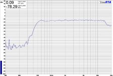
Here's Martin's measurement of the frequency response of a JBL 2420 (aluminum diaphragm, 1" exit, no longer in production) mounted on a AH-550 with a 350 Hz 24 dB/oct highpass filter - microphone at horn mouth, 1/24th octave smoothing.
Here's Martin's measurement of the frequency response of a JBL 2420 (aluminum diaphragm, 1" exit, no longer in production) mounted on a AH-550 with a 350 Hz 24 dB/oct highpass filter - microphone at horn mouth, 1/24th octave smoothing.
Attachments
Re: More AH-550 Information
Nice! But what is the response like off-axis?
Lynn Olson said:
Here's Martin's measurement of the frequency response of a JBL 2420 (aluminum diaphragm, 1" exit, no longer in production) mounted on a AH-550 with a 350 Hz 24 dB/oct highpass filter - microphone at horn mouth, 1/24th octave smoothing.
Nice! But what is the response like off-axis?
A interesting and timely subjective "review":
http://www.stereotimes.com/speak010708.shtml
Hmm, I wonder what the compression driver is?
http://www.stereotimes.com/speak010708.shtml
Hmm, I wonder what the compression driver is?
Re: More AH-550 Information
Good question. I suspect LeCleac'h horn/waveguides are in a different family than constant-directivity oblate-spheroid and other constant-directivity waveguides. It seems entirely possible that LeCleac'h profiles optimize FR and time response over constant directivity design goals, following the guidelines of Philip Newell and Dr. Keith Holland for minimum horn coloration.
From page 108 of Newell and Holland's "Loudspeakers for Music Recording and Reproduction":
"By the very careful choice of design parameters and construction, horns can be produced for use above 1 kHz, or thereabouts, which approach the performance of electrostatic loudspeakers with their very low levels of of deviation from their intended amplitude and phase (and hence time) responses. It would appear, however, there are finite practical limits to the performance ranges over which horns can produce near optimum results:
1) The cut-off frequency of a horn is a function of its rate of flare. A low cut-off frequency demands a slow rate of flare.
2) If "horn-like" sound characteristics are to be avoided in a practical horn, the length should not exceed 12" (300 mm) or thereabouts.
3) Taking 1 and 2 together, if a horn has a low flare rate, and cannot exceed 12 inches in length, then given a 1" throat diameter, and, say, a 250 Hz cut-off frequency, the horn will inevitably have a small mouth area. There will be consequently be an abrupt change in cross-sectional area where it meets the outside air. [Impedance and FR graphs of two horns like this are shown.] As musical reproduction devices they were not considered smooth, flat, or natural, despite not sounding horn-like.
4) In order to achieve a smooth and trouble-free mouth termination, from a 1" throat of a horn not exceeding 12" in length, a mouth diameter of of around 12" would appear to be the smallest practical size. This dictates a flare rate which results in a cut-off in the order of 1 kHz, but can yield exceptionally smooth performance through cut-off if carefully designed, even allowing use through cut-off, and utilising the acoustic roll-off as part of the electroacoustic crossover [Impedance and FR of sample horn shown.]
5) To minimise internal disturbances which can cause disruption to both the on- and off-axis responses, all corners, angles, and obstructions should be removed, rendering axial symmetry and smoothly contouring surfaces. Figure 4.11 shows the logarithmic throat impedance plots of all but one of the horns used in these tests. The vastly superior characteristics of AX2 (Sample 8) can be readily seen.
6) "Squashing" the axisymmetric shape into an ellipse would perhaps allow some change in directivity pattern without with undue disturbance of of the time response.
Sample 8, mated with the TAD 2001 drive unit produced what would seem to be a near optimum response in terms of both phase and amplitude (hence time), smooth directivity, a very smooth overall performance from 1 khz to beyond 20 kHz, and was deemed to be very musical, natural, transparent, and definitely not horn-like. It is interesting that in physical dimensions, though not in its drive system, it strongly resembles the Tannoy Dual Concentrics from around 40 years before. The fact that the shape and size were so similar to the Tannoy 15 inch Dual Concentric HF horn served to explain why the latter had enjoyed 40 years of use without being considered to sound horn-like. It would appear that the Tannoy, all of those years ago, defined the physical limits for accurate performance, beyond which horns run into trouble."
From page 113:
"The AX2 was designed to minimise the impedance irregularities, which was clearly successful, but the size and directivity were the natural result of the design, and could not be controlled. Larger mouths could be smooth down to lower frequencies, but could give rise to difficulties in closely locating adjacent drivers at crossover points. The practice of mounting HF horns and/or drivers on the central axis of the larger horn may ruin the mouth termination of the latter. The AX2 just about defines the practical limit for a MF/HF horn if the highest quality audio is the sole aim."
I am in agreement with Newell and Dr. Holland on essentially all of the points. I'm primarily interested in smooth FR, time/phase response, and directivity (most importantly, without narrow spikes only a few degrees wide). I'm less interested in a specified degree of directivity than I am in freedom from narrow artifacts in frequency, time, or spatial domains - thus the interest in drivers that are free from breakup in the working band, horn/waveguides that are free of internal obstructions, and phase-plugs that emit coherent wavefronts. Smooth driver response without a lot of wacko equalization is a major advantage in my book - and I'm aware this isn't a fashionable viewpoint in the pro and audiophile worlds these days.
ScottG said:
Nice! But what is the response like off-axis?
Good question. I suspect LeCleac'h horn/waveguides are in a different family than constant-directivity oblate-spheroid and other constant-directivity waveguides. It seems entirely possible that LeCleac'h profiles optimize FR and time response over constant directivity design goals, following the guidelines of Philip Newell and Dr. Keith Holland for minimum horn coloration.
From page 108 of Newell and Holland's "Loudspeakers for Music Recording and Reproduction":
"By the very careful choice of design parameters and construction, horns can be produced for use above 1 kHz, or thereabouts, which approach the performance of electrostatic loudspeakers with their very low levels of of deviation from their intended amplitude and phase (and hence time) responses. It would appear, however, there are finite practical limits to the performance ranges over which horns can produce near optimum results:
1) The cut-off frequency of a horn is a function of its rate of flare. A low cut-off frequency demands a slow rate of flare.
2) If "horn-like" sound characteristics are to be avoided in a practical horn, the length should not exceed 12" (300 mm) or thereabouts.
3) Taking 1 and 2 together, if a horn has a low flare rate, and cannot exceed 12 inches in length, then given a 1" throat diameter, and, say, a 250 Hz cut-off frequency, the horn will inevitably have a small mouth area. There will be consequently be an abrupt change in cross-sectional area where it meets the outside air. [Impedance and FR graphs of two horns like this are shown.] As musical reproduction devices they were not considered smooth, flat, or natural, despite not sounding horn-like.
4) In order to achieve a smooth and trouble-free mouth termination, from a 1" throat of a horn not exceeding 12" in length, a mouth diameter of of around 12" would appear to be the smallest practical size. This dictates a flare rate which results in a cut-off in the order of 1 kHz, but can yield exceptionally smooth performance through cut-off if carefully designed, even allowing use through cut-off, and utilising the acoustic roll-off as part of the electroacoustic crossover [Impedance and FR of sample horn shown.]
5) To minimise internal disturbances which can cause disruption to both the on- and off-axis responses, all corners, angles, and obstructions should be removed, rendering axial symmetry and smoothly contouring surfaces. Figure 4.11 shows the logarithmic throat impedance plots of all but one of the horns used in these tests. The vastly superior characteristics of AX2 (Sample 8) can be readily seen.
6) "Squashing" the axisymmetric shape into an ellipse would perhaps allow some change in directivity pattern without with undue disturbance of of the time response.
Sample 8, mated with the TAD 2001 drive unit produced what would seem to be a near optimum response in terms of both phase and amplitude (hence time), smooth directivity, a very smooth overall performance from 1 khz to beyond 20 kHz, and was deemed to be very musical, natural, transparent, and definitely not horn-like. It is interesting that in physical dimensions, though not in its drive system, it strongly resembles the Tannoy Dual Concentrics from around 40 years before. The fact that the shape and size were so similar to the Tannoy 15 inch Dual Concentric HF horn served to explain why the latter had enjoyed 40 years of use without being considered to sound horn-like. It would appear that the Tannoy, all of those years ago, defined the physical limits for accurate performance, beyond which horns run into trouble."
From page 113:
"The AX2 was designed to minimise the impedance irregularities, which was clearly successful, but the size and directivity were the natural result of the design, and could not be controlled. Larger mouths could be smooth down to lower frequencies, but could give rise to difficulties in closely locating adjacent drivers at crossover points. The practice of mounting HF horns and/or drivers on the central axis of the larger horn may ruin the mouth termination of the latter. The AX2 just about defines the practical limit for a MF/HF horn if the highest quality audio is the sole aim."
I am in agreement with Newell and Dr. Holland on essentially all of the points. I'm primarily interested in smooth FR, time/phase response, and directivity (most importantly, without narrow spikes only a few degrees wide). I'm less interested in a specified degree of directivity than I am in freedom from narrow artifacts in frequency, time, or spatial domains - thus the interest in drivers that are free from breakup in the working band, horn/waveguides that are free of internal obstructions, and phase-plugs that emit coherent wavefronts. Smooth driver response without a lot of wacko equalization is a major advantage in my book - and I'm aware this isn't a fashionable viewpoint in the pro and audiophile worlds these days.
- Home
- Loudspeakers
- Multi-Way
- Beyond the Ariel