")
Yes indeed, glad to hear you're making good progress Lynn. Sounds like you've mastered the cane better than I did when I smashed my toes up a few months back -it was my elbow getting tired that I found hardest.
Re mouth distortion et al, if Ron Clarke's findings are anything to go by, then curving it improves things dramatically. I added a mild curve to a quick test pair of pipe-horns last year at his suggestion, and the difference was audible -beyond what you could write off as wishful thinking. Wish I still had my measurement gear.
Best
Scott
P.S. -Dan; you're not kidding about the grapeseed extract. I've taken it for the past 18months or so, since you suggested it, and it certainly does have a positive effect. If I stop for a few days, I find my concentration levels in particular drop. FWIW, I've found a nice balance with 200mg of the GSE, 1g of vitamin C, and 100mg of vitamin e daily, with gineseng alternate months.
All health tips very much appreciated. I've been taking 360mG of calcium+zinc+magnesium for several months now, on general principles that more calcium during the bone reconstruction process is a good thing - also makes it less likely the calcium needed for reconstruction will be stolen from other bones or my teeth. I'll be picking up some grapeseed extract and giving it a try.
There's a thread over in HTGuide.com that shows promising measurements of the 18Sound XT1086 waveguide with a BMS 4540ND 1" compression driver. On this thread, our distinguished guest Dr. Geddes is offering his own OS waveguide for $250 each. Looks to me like there are some very good waveguides here, with Earl's WG having the significant advantage of being free of the diffraction slot of the XT1086.
The frequency response of the 12" Alnico Tone Tubby is actually pretty decent for a guitar speaker, although it's clear that some kind of notch filter is needed along with the lowpass crossover in the 1.5~2 kHz region, where it can meet the tweeter. The tweeter is going to need some frequency shaping as well (a shelf filter) but this should be straightforward. You will need to measure as you build the system - this is too complex for the "twiddle until it sounds good" approach.
Note the comments elsewhere in the HTGuide thread that the builder had good luck with a rear-facing tweeter to complement the front-facing horn, a la Linkwitz. Dr. Geddes and Linkwitz have completely different views on rear-facing tweeters and the desired directivity patterns, so you'll see disagreement on that subject. I plan to use a rear-facing tweeter on my own system, whether I go with compression drivers or the new RAAL ribbon tweeter.
Whew! That sets a new record for the most number of links I've put in a single posting!
Speaking of ribbons, it's interesting the Swans/HiVi have a pro box with horn loaded ribbons - 4 ribbons!
http://www.swanspeaker.com/product/htm/view.asp?id=32
I've never heard such a thing - wish I could pop over to the new Pasadena store to have a listen.
4 ribbons, 1 horn? How can that work well?
http://www.swanspeaker.com/product/htm/view.asp?id=32
I've never heard such a thing - wish I could pop over to the new Pasadena store to have a listen.
4 ribbons, 1 horn? How can that work well?
Hi Lynn
Man I hope you heal up soon, that is a pain wobbling around, not to mention trying not to re-injure it inadvertently.
The “megaphone coloration” like in the 20’s when they were used for singing, may be the effect the added frequency dependant acoustic load has on your vocal system / sinus cavities, I don’t know for sure.
I do know that of the various types, to the extent that a horn is constant directivity, it has an on axis response, which tracks its radiated acoustic power, and that no compression driver by itself has “flat” power response.
For acoustic loading purposes, a horn has in effect a “high pass” function related to the rate of expansion.
Also, that because of the fast initial expansion at the apex, a conical horn has less acoustic loading on the lower frequency end of the drivers range, compared to an exponential horn with the same mouth size.
From the directivity standpoint, while an old style exponential horn could be nearly flat on axis with the same driver, it will sound dark and murky everywhere off axis because the reverberant field in the room is nearly the same spectrum as the power response (which is actually rolled off like the drivers power response).
A big round exponential horn would actually be the worst possible in this regard, very narrow focused highs and ever widening pattern as the frequency falls.
While its narrowing radiation pattern off sets (in a perfect world) the falling acoustic power from the driver directly on axis with increasing frequency, it does not produce anything near a flat power response.
It is also perfectly possible not to have the slightest trace of “that” or “horn” coloration with a conical horn, which was the original point.
In RF work, conical horn waveguides are most common horn type fwiw.
For diffraction, size is your friend. Re-radiation at edges etc is related to the magnitude of the pressure gradient or “how fast” the pressure changes within a space.
Consider Earl’s clever horn flare, it is the slowest gradient possible between the two sets of angles (plane wave to diverging angles).
The larger the horn mouth is, the lower the pressure is AND the lower the frequency is that the horn confines the radiation angle, this also inhibits out of pattern radiation.
The larger the mouth is (for a fixed radiation angle), the greater the difference between the “in pattern” power to the total off axis radiated power (quieter it is to the side and rear outside the pattern).
Conceptually horn mouths shaped like the Tractrix are very appealing and logical, however, when you measure the spherical radiation patterns on real horns, one finds they are essentially the same as an exponential of the same size, that is, when large enough to begin with, the fancy radius outer edge has no real impact on the radiated sound.
Also you find that the outer edges are active only at / near the horns low cutoff and effect directivity somewhat above that only.
For a conical horn, it is an advantage in pattern control at the low frequency end of its pattern control range if the last third or so of the horn, has a greater angle, as found by Don Keele. Most horns employ some form of end flare angle change for the same reason.
This combats the narrowing that would normally be present as the pattern loss frequency is approached (going down in frequency).
Speaking of that (pattern loss), it is also desirable NOT to have the H and V horn wall angles significantly different as one plane losses control before the other and then one has “pattern flip” where the narrow angle is wide and visa versa.
Perhaps the biggest fear related / problem issue with conical and CD horns in general is that they are not going to be “flat” without compensation.
It would be nice “if” the were already flat and had a nice resistive impedance for a passive filter but they don’t (generally).
This makes them more difficult to apply and you pretty much have to measure what you have to have some hope of making it right.
Essentially no way you can get to a good response with a passive filter without computer help and measurements.
On the other hand, other peoples listening tests generally show a preference for speakers that had a reverberant field with the same / similar spectrum as the on axis sound.
This is a speaker with constant directivity, something direct radiator’s don’t usually have.
With directivity or increasing “front to back ratio”, comes with an increased “near field” where the best stereo is.
Hope your leg mends, don’t rule out horns.
Best,
Tom Danley
Hi Tom, good to hear from again!
Fear not, the surgeon said a month ago the bone could bear my full body weight (a not inconsiderable 240 lbs), and that it now needed walking-type exercise to continue the return to full strength and a completely normal appearance on the X-ray.
It was after the visit to the doc that I discovered although the bone may have been fine, I was nowhere close to being able to walk - I couldn't even make the first step with a cane. It was only on a subsequent visit to the Physical Therapist I discovered the upper leg didn't have the strength to sustain walking. Thus, the past month of various strength-and-balance exercises, and increasing mobility, day by day. Little did I think as I crawled up that frozen driveway on January 7th that I'd still be recovering by midsummer.
There has been a lot of change this last month, though, much faster than before. With any luck at all I won't be needing a cane for the RMAF this September, although I may need frequent sit-downs. Long-distance air travel might be quite a ways off, and I suspect economy (lower circle of Hell) class may be out for good. No loss there.
Thanks for the additional info on conical horns. I really need to give these a serious audition, and of course your Unity horn most of all. Where I part from the Toole-school is a preference for the summed room energy and the direct-arrival having a similar spectra, and if necessary, using a rear horn (connected out of phase) to boost overall room energy to get the spatial impression I like (big fan of electrostats here).
I realize this may be anathema to the whole controlled-directivity design school, but shucks, it's my loudspeaker, and I intend to give it the spatial qualities I've always aimed for. My entree into high-end audio was the Shadow Vector quadraphonic decoder, so a smooth and evenly dispersed spatial quality is important to me.
In the early Seventies, we went to some trouble in the variable-parameter decoder design to avoid "detenting" at the speaker location, which was considered a very undesirable artifact that degraded the natural impression of the soundfield. The goal was a system that had no impression of speaker location at all, something I heard for myself at the BBC in 1975, so I know it's possible, even in very small rooms. I still aim for that "no-box, no-speaker" quality today - but now I'm interested in high-dynamic-range systems as well.
I want to express my thanks for the contributions from you and Dr. Geddes here at diyAudio, in this thread and others. I've never been a devotee of the Temple of Altec, but do want to understand more about what horns and/or waveguides do well, and what they aren't so good at. Most of all, I'm interested in high-efficiency systems with well-behaved decay characteristics - low diffraction, low resonance, low energy storage, etc.
Lynn Olson said:but do want to understand more about what horns and/or waveguides do well, and what they aren't so good at. Most of all, I'm interested in high-efficiency systems with well-behaved decay characteristics - low diffraction, low resonance, low energy storage, etc.
I am most interested in "high-efficiency systems with well-behaved decay characteristics - low diffraction, low resonance, low energy storage, etc." which is what the Summa does exceptionally well (in addition to having controlled narrow coverage, which you did not mention). I did not come to this design by accident but by seeking the best solution to the things that you mentioned. If you can find an alternative solution to these same problems - that is cost effective!!! - I'd be very interested. The Summa is very cost effective - its really quite a simple design.
Tom Danley said:Hi Lynn
In RF work, conical horn waveguides are most common horn type fwiw.
that is, when large enough to begin with, the fancy radius outer edge has no real impact on the radiated sound.
Also you find that the outer edges are active only at / near the horns low cutoff and effect directivity somewhat above that only.
For a conical horn, it is an advantage in pattern control at the low frequency end of its pattern control range if the last third or so of the horn, has a greater angle, as found by Don Keele. Most horns employ some form of end flare angle change for the same reason.
This combats the narrowing that would normally be present as the pattern loss frequency is approached (going down in frequency).
Perhaps the biggest fear related / problem issue with conical and CD horns in general is that they are not going to be “flat” without compensation.
Tom
We do see things differently - some because of our situations.
You need to defend the conical horn because you use them, and I need to defend the OS because I use it. Lets remember that the OS and the conical are identical at the mouth. But unless you can somehow set up a spherical wavefront at the throat of the conical horn, you will have a great deal of HOM to deal with at the mouth. You do not seem to acknowledge this in any of your discussions.
Compression driver phase plugs are intende to delay the outer edges of the dome so that all portions of the domes radiation arrive at the throat aperature in-phase - i.e. planar. This is the intent, but things don't alway work out so well. (See my patents on phase plugs.) When I was at B&C we did some measurements of the flatness of the wavefront at the exit aperature of a compression driver. They were pretty good. I am setting up a test fixture here to measure this very precisely for compression drivers as it is a critical factor for HF pattern control and HOMs. On a conical horn the flatness of the compression drivers exit wavefront would be completly lost in the diffaction caused by the abrupt change in wall slope at this aperature. On a OS waveguide the flatness of this wavefront can be seen very clearly in the very HF pattern of the system.
I don't completely follow your mouth discussions, but your claims don't coincide with what we have found. We have not found a mouth size that does not have diffraction, and I don't see how there could ever be a mouth that did not have this effect. While the pressure does drop with R (the radius), the length of the diffracting edge increase with R, so in theory, the diffraction is independent of the mouth size. We have found this to be mostly true, but with one caveate. The mouth effects broaden in frequency and move lower as the mouth size increases until they "dissipate" into the lack of coverage control at the waveguides lower frequency limit - so they could appear to go away. The extra angle that Keele talks about has the exact same effect as a radius, except that the abrupt slope change causes a larger diffraction than a radius will have, but both are intended to improve the LF pattern control. Keele and JBL now use a radius in their newer devices.
You said "something direct radiator’s don’t usually have" and I would like to point out that NO direct radiator can be CD - its a physical impossibility. Unless of course you consider omni-directional to be CD (which I don't) because then a very small radiator can be omni-directional up to some frequency. But no direct radiator can be CD with a defined coverage pattern less than omni.
Baffle edges
Just a wild idea - here goes.
The baffle width in a dipole governs the frequency at which there is a transition from the LF behaviour (6db/oct rolloff) to the HF (response ripples where the path difference gives destructive interference). A large baffle width increase LF extension and power handling, but brings the ripples down in frequency - Linkwitz has lots of graphs of this stuff.
If the edge of the baffle goes through a transition from solid to open over some fraction of a baffle width, we should get an effect like apodisation in optics or antenna design. The ripples should largely disappear as there is no longer a single path length difference.
I have on idea what you use to make a partially transmitting panel - felt? perforated sheet of some sort?
Is this entirely stupid?
Hi Earl
I think the BMS driver we use is maybe a different duck.
Internally, its exit is one inch, it is a conical horn down to about 1 / 2 inch diameter in a little more than 1 inch length. At that size, the slots from the radiator arrive radially but there is only one path length, not multiple paths as in a most dome drivers.
It is a conical horn that starts at about 1 / 2 inch in diameter, connecting to another conical horn at the one inch point
I see what your OS horn is accomplishing, it is cool.
What I have to design for my job serves a different purpose, often, the speaker will have to set next to one or more identical units or on a wall boundary in order to get the coverage angle the contractor / installer needs.
The concept that one can array trap shaped speakers like this at all is largely a marketing one, as the supposed superiority of the line source is now.
However, it turns out that if one uses big conical horns AND you place them so the walls are parallel and close together, apex’s as close as possible, then, you measure something a LOT closer to an ideal summed pattern with comparatively little unit to unit interference.
The remaining problem is that with a horn that is two 50 by 50 boxes, you get 100 by 50 BUT also the pattern flip at the control loss point.
The reference to the tractrix was in that its radius extends to a flat plane (baffle), not that a radius at the lf kink wasn’t a good idea (it is).
I am not say that one might find an improvement with absorbing foam around the mouth etc too. I may well be describing the mouth thing unclearly but there is what I observe.
For a given conical horn wall angle and shape, increasing the final size, lowers the pattern loss frequency as expected and higher up, baring physical radiation from the horn body) one see’s the ratio between the energy inside the pattern and outside the pattern continue to increase.
By the time one has a 60 degree conical horn like this that is say 2 or 3 feet across at the mouth, very little high frequency energy is radiated at say 90 degrees off axis.
As you make the horn acoustically smaller, the front to back ratio goes down, more energy spills outside the pattern.
I am not suggesting a 3 foot wide horn is practical in a living room.
I am suggesting that what I have measured is (on these horns) the high frequency energy radiated energy outside the pattern falls with increasing horn mouth size.
For example on a square 50 degree horn that is 28 inches at the mouth, at 90 degrees off axis, it reaches –20dB about 500Hz and –30 dB about 7KHz.
“You said "something direct radiator’s don’t usually have"”
Yeah, I didn’t feel like a long explanation but didn’t want to say “don’t have” concretely because then someone might come back and say “what about an omni”, which is an exception and then there is when it is /isn’t.
Best,
Tom
Tom,
Glad to see you guys here. Hope I'm not to OT, but I had to take the opportunity to ask.
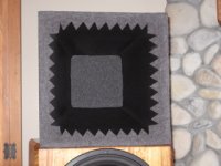
Background: I have a set of Nick's Unity horns and the tweeter is the TAD 2001. I found that Earl's foam treatment does improve the highs and eliminates any slight "horn" character. I had filled the entire horn with the foam - all the way to the phase plug of the tweeter, but with the front half removed, it seems to do just as well - I don't think I can hear a difference. As the picture shows, I'm also playing with some thick wool felt at the exit. Seems to add a touch of clarity to the highs (but could be my imagination too).
I'm interested in your comments regarding the transition from the tweeter to horn, especially for the BMS driver you are using. The TAD, of course has a much deeper throat and a narrow taper. Nick made somewhat of a transition zone, and I worked it a little more to get as smooth and gradual a transition as possible in the short distance available. I'm wondering; since the BMS would seem to avoid the steep transition, whether it wouldn't be the best choice here? The shorter throat has another seeming advantage. Right now, I'm using a DEQX, which can digitally align the drivers. At some point, I want to try analog crossovers again and get the phase worked out at the crossover point. The longer throat of the TAD would seem to make the timing issue more difficult. I'd appreciate your thoughts.
BTW, I'm getting some nice sounds out of these.
Thanks,
Sheldon
Glad to see you guys here. Hope I'm not to OT, but I had to take the opportunity to ask.
Background: I have a set of Nick's Unity horns and the tweeter is the TAD 2001. I found that Earl's foam treatment does improve the highs and eliminates any slight "horn" character. I had filled the entire horn with the foam - all the way to the phase plug of the tweeter, but with the front half removed, it seems to do just as well - I don't think I can hear a difference. As the picture shows, I'm also playing with some thick wool felt at the exit. Seems to add a touch of clarity to the highs (but could be my imagination too).
I'm interested in your comments regarding the transition from the tweeter to horn, especially for the BMS driver you are using. The TAD, of course has a much deeper throat and a narrow taper. Nick made somewhat of a transition zone, and I worked it a little more to get as smooth and gradual a transition as possible in the short distance available. I'm wondering; since the BMS would seem to avoid the steep transition, whether it wouldn't be the best choice here? The shorter throat has another seeming advantage. Right now, I'm using a DEQX, which can digitally align the drivers. At some point, I want to try analog crossovers again and get the phase worked out at the crossover point. The longer throat of the TAD would seem to make the timing issue more difficult. I'd appreciate your thoughts.
BTW, I'm getting some nice sounds out of these.
Thanks,
Sheldon
Attachments
Re: Baffle edges
Not at all. The reference to apodization in optical or RF work is appropriate; using a lossy boundary seems like a good way to sidestep the spatial, time, and frequency-domain ripples of a hard-edged boundary. I made a suggestion some 20 pages back of having an inner mesh, wrapping felt around that, and wrapping an outer mesh around that. If the holes are much smaller than the highest frequency of interest, and the felt is chosen for good wideband absorption (I've found that wool felt has the best wideband absorption characteristic), the edge termination should be substantially improved.
This should be readily measurable in both near and far-field - I'd look in the time domain first, where the difference between a diffuse and sharp edge should be most obvious. I still wonder how a horn or waveguide would behave differently if the mouth of the free-standing horn was a lossy structure with lots of perforations in the outermost portions.
I plan to experiment a fair bit with the open baffle, with the goal of minimizing fine-grained dispersion "spikes" at off-axis angles. These narrow "spikes" appear at critical angles of conventional sharp-edged enclosures, so I expect to find them in open baffles, too (just at different angles). This is where I expect lossy edge structures to make a difference.
Although I don't mention it a whole lot in the Ariel pages, I'm always wary of ripples in the time domain that have a strong spatial dependency - particularly if the ripple is only a few degrees wide. This is an obvious indication of diffraction, reflection, or combined artifacts.
PigletsDad said:Just a wild idea - here goes.
The baffle width in a dipole governs the frequency at which there is a transition from the LF behaviour (6db/oct rolloff) to the HF (response ripples where the path difference gives destructive interference). A large baffle width increase LF extension and power handling, but brings the ripples down in frequency - Linkwitz has lots of graphs of this stuff.
If the edge of the baffle goes through a transition from solid to open over some fraction of a baffle width, we should get an effect like apodisation in optics or antenna design. The ripples should largely disappear as there is no longer a single path length difference.
I have on idea what you use to make a partially transmitting panel - felt? perforated sheet of some sort?
Is this entirely stupid?
Not at all. The reference to apodization in optical or RF work is appropriate; using a lossy boundary seems like a good way to sidestep the spatial, time, and frequency-domain ripples of a hard-edged boundary. I made a suggestion some 20 pages back of having an inner mesh, wrapping felt around that, and wrapping an outer mesh around that. If the holes are much smaller than the highest frequency of interest, and the felt is chosen for good wideband absorption (I've found that wool felt has the best wideband absorption characteristic), the edge termination should be substantially improved.
This should be readily measurable in both near and far-field - I'd look in the time domain first, where the difference between a diffuse and sharp edge should be most obvious. I still wonder how a horn or waveguide would behave differently if the mouth of the free-standing horn was a lossy structure with lots of perforations in the outermost portions.
I plan to experiment a fair bit with the open baffle, with the goal of minimizing fine-grained dispersion "spikes" at off-axis angles. These narrow "spikes" appear at critical angles of conventional sharp-edged enclosures, so I expect to find them in open baffles, too (just at different angles). This is where I expect lossy edge structures to make a difference.
Although I don't mention it a whole lot in the Ariel pages, I'm always wary of ripples in the time domain that have a strong spatial dependency - particularly if the ripple is only a few degrees wide. This is an obvious indication of diffraction, reflection, or combined artifacts.
Re: Re: Baffle edges
I've heard edge slots - starting small and getting wider toward the lip. Sounded great to me, very clean. But I'll admit I did not hear the same horn without the slots.
A bit of edge treatment experimenting here with foam, towels, felt and screen has yielded promising results as judged by ear.
Should try the same thing on the baffle edges.
Lynn Olson said:I still wonder how a horn or waveguide would behave differently if the mouth of the free-standing horn was a lossy structure with lots of perforations in the outermost portions.
I've heard edge slots - starting small and getting wider toward the lip. Sounded great to me, very clean. But I'll admit I did not hear the same horn without the slots.
A bit of edge treatment experimenting here with foam, towels, felt and screen has yielded promising results as judged by ear.
Should try the same thing on the baffle edges.
Hi
Tom, the tapped horns are an interesting approach. I like very much the coaxial arrangement as there is nothing that can substitute for that IMO.
As we had to learn throughout that thread, EVERY discontinuity of a surface the wave front travels along creates diffraction and builds up a "second source" . The mechanism is basically an increase or decrease of space to radiate in.
This should also occur when the wave front of the tweeter - located at the throat of the horn - reaches the bass drivers located halfway to the mouth.
The diffraction - and therefor the HOM of the tweeter as well - should be modulated also by the bass membrane when moving out and in, no ?
Is this audible ?
Greetings
Michael
Woohoo, 148 pages... way to procrastinate. Lynn I thought I was indecisive but you're the man.
So come on Lynn at least show us a cheeky shot of some wood/MDF dust or maybe a full frontal shot of some panels cut to size. Considering the thread, doing something like that would be rather surreal.

So come on Lynn at least show us a cheeky shot of some wood/MDF dust or maybe a full frontal shot of some panels cut to size. Considering the thread, doing something like that would be rather surreal.
What Awaits
Well, I'm making progress. Today I was able to use my cane to go up 8 steps, then down again (going upstairs, that is). This is the first time I've walked up the stairs since January 7th, so that's a good sign. In a few days time I may be strong enough to go up and down the entire flight of stairs, including the landing with its 180-degree turn and a step in the middle.
From the time of about mid-February to the present I crawl down on the floor, rotate around and sit on my butt, hoist myself up by my arms step by step (hard work!), scoot around the 180-degree landing, go up some more stairs, then haul myself back up onto the walker. I do this several times a day, since I sleep upstairs and watch TV, read books, socialize, and eat downstairs. (The first month of living downstairs and sponge baths was not much fun.)
The basement stairs unfortunately have neither carpeting nor railing, both a prerequisite at this stage of mobiliity. But as mentioned above, things are getting better day by day. I'm hoping by the time of the RMAF to have a pair of test baffles, made a set of measurements of driver candidates, and done some preliminary auditions.
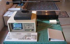
The gear you see in the picture (taken last December) has been patiently awaiting my return - the MLSSA/DOS computer on the left, the CC-2 power amp on the right, and the 1/2" ACO Pacific microphone and low-diffraction stand assembly at the top of picture. The WinXP dual Athlon HTPC with its M-Audio 192/24 soundcard will join it after I buy and install SoundEasy.
Well, I'm making progress. Today I was able to use my cane to go up 8 steps, then down again (going upstairs, that is). This is the first time I've walked up the stairs since January 7th, so that's a good sign. In a few days time I may be strong enough to go up and down the entire flight of stairs, including the landing with its 180-degree turn and a step in the middle.
From the time of about mid-February to the present I crawl down on the floor, rotate around and sit on my butt, hoist myself up by my arms step by step (hard work!), scoot around the 180-degree landing, go up some more stairs, then haul myself back up onto the walker. I do this several times a day, since I sleep upstairs and watch TV, read books, socialize, and eat downstairs. (The first month of living downstairs and sponge baths was not much fun.)
The basement stairs unfortunately have neither carpeting nor railing, both a prerequisite at this stage of mobiliity. But as mentioned above, things are getting better day by day. I'm hoping by the time of the RMAF to have a pair of test baffles, made a set of measurements of driver candidates, and done some preliminary auditions.
The gear you see in the picture (taken last December) has been patiently awaiting my return - the MLSSA/DOS computer on the left, the CC-2 power amp on the right, and the 1/2" ACO Pacific microphone and low-diffraction stand assembly at the top of picture. The WinXP dual Athlon HTPC with its M-Audio 192/24 soundcard will join it after I buy and install SoundEasy.
Attachments
My hifi pal Thom Mackris has a woodworker friend in Lyons, Colorado who I hope to use to build the first set of test baffles - interchangeable 12" and 8" mounts with appropriate recessing, etc.
With any luck this stuff will fit into the rear area of my Subaru Outback - 4WD and reasonable ground clearance is a necessity here in Colorado, since the weather here is so unpredictable and potentially dangerous. Nothing like the soft and gentle rain (and winter gloom) of the Pacific Northwest or Northern Europe.
The day before yesterday we had a microburst with 100mph winds that lasted about ten minutes, and this evening we had a violent thunderstorm with almost continuous lightning that lasted a half-hour. In the winter, it can go from brilliantly sunny to a full-on blizzard with the visibility almost zero in the space of less than an hour. The local joke is that Kansas' tornadoes start here - except it's not a joke, it's true.
I looked at that first posting in this thread dated 3-27-07 and didn't know whether to laugh or cry. So much time has gone by. That terrible 6-week snowstorm has taken more than 6 months out of my life, and permanently changed my personality - I can only hope for the better.
Thanks again to BudP for making the initial suggestion to get this project out of the mental domain and out into the larger world of the diyAudio community. Since he went through a similar experience when he was 18, he knew that I was probably starting to go a little stir-crazy by that point - there's nothing more soul-destroying than daytime television, and reading one science-fiction book after another was starting to get to me.
It was Bud's quite strongly expressed suggestion to re-join this forum and discuss the project that I was planning to do this last Spring - and will indeed do once I am physically able. I've heard enough of the local high-efficiency speakers around here that I am strongly motivated to do my own system, this time with the Ariels as the reference point.
- Home
- Loudspeakers
- Multi-Way
- Beyond the Ariel