Lynn Olson said:
I was thinking of a sealed box, actually, since the feedback servo takes care of most of the distortion. The primary benefit of vented is substantially reduced excursion (and distortion) close to the vent frequency. With servo, that benefit mostly disappears, leaving increased SPL as the remaining asset - but with the drawbacks of vent coloration and a 4th-order highpass characteristic.
In a servo setup, what are the sealed-box DISadvantages? Curious to know.
-----
It is interesting that Rythmik is addressing the same concerns that I'm looking at, just in a different frequency band. It does make you think about custom drivers for the Bass array in the OB, although that's a project for another day.
Ah - but the servo does NOT take care of most of the distortion - at least not around resonance. Think of it more as:
1. A very good motor design with triple shorting rings that lower distortion above resonance. The Dayton HiFi sub drivers from PE are largely comparable here.
2. Unlike the Dayton drivers - transient capability for an underhung, long gap high excursion design with a lossy surround, is radically improved *except* near resonance (..and even there its improved somewhat).
Basically the servo is increasing driver "control" both in the mass controlled and compliant controlled region. Its more effective in the mass controlled region (no surprise there), but while being less controlled at the lower end in the compliance region - a servo is perhaps better here than most designs. At resonance though, (and near resonance - which is "q" dependent), its still not very good.
Anyway..
Any given design shifts driver resonance up depending on driver param's and cabinet size.
The first question then is:
Where is the resonance in relation to the operating passband?
If possible we do NOT want this in the range of fundamentals. IF thats not possible we would rather have:
1. a narrow "q" design (usually a low qts value), and/or
2. a mechanical limiter.
Because we are operating the sub at higher freq.s - pushing the resonance up beyond our crossover isn't really an option (..and even if it was compliance related distortion is still a problem even with a servo - and then there is the excursion vs. spl problem and a distinct potential to "bottom-out" the driver).
None of the drivers are particularly narrow "q" designs - the lowest being the DS12CV with a qts of .327. So we move to a mechanical limiter.
Now the servo IS a mechanical limiter.. to an extent. I liken its capability to that of a "fine adjustment" control. What we need then is a "coarse adjustment" control - one that is specifically designed to keep the driver "in the gap" at and near resonance (..which is hard to do electrically). Of course a ported design provides this "coarse adjustment" control.
A ported design mechanical dampens and limits a driver's operation (..at least where the port air-load is mass controlled - i.e. above port resonance). It is however crude and "lossy" when compared to a servo (hence the "coarse adjustment" designation).
Now to get "maximum" value from the port design it needs to be "tuned" at *least* an octave away from the in-box driver resonance, and preferably further than that. (..again, its basically a extending mass controlled character to lower freq.s.) If its to close to the driver's resonance then you are potentially compounding the error by adding poor driver control to poor port control.
Of course at, (and particularly just below *port* resonance), the port is horrible. Linear and non-linear distortion are very poor in this region. The best thing you can do here is move it out of your fundamental range, (and even as far out into the harmonic range as is feasible). (Understanding of course that this puts additional excursion & thermal strain on the driver.. the lower the port tunning freq. is.) Another reason for a lower port tunning freq. is group delay, push it low enough in freq., (half octave + below any fundamental), and it won't be an audible problem even if at resonance its hovering a bit above 50 mil. sec.s. More importantly, combined phase has a nice gradual rotation in such a design (in the region above resonance).
A few more notes on Ported designs:
1. There is an obvious constraint on port tunning and port length - especially when factoring in a larger port "area". Unfortunately..
2. The port diameter should be large to keep the "slug of air" in the port and limit its excursion. (..otherwise you'll suffer from excursion limiting that will limit output at higher spl's.) Don't think that multiple ports vs. one large port are comparable, they aren't. While multiple ports have greater surface friction and reduce air speed and ultimately port turbulence, they do not decrease air excursion to the same extent (..and of the two decreasing air excursion is more important for most sub designs).
3. A good port design is preferable to a PR.. Linear decay behavior above resonance is usually a LOT better - in fact it may be better than the driver anywhere near this freq.., at least for the first few mil. sec.s (..which seem to have the largest effect on perceived clarity/transparency).
Need to chew on this for awhile.
Feedback systems are nothing more than input/output comparators. The Rhythmik is a feedback system that compares the input voltage of the amplifier with some sort of analog of driver acceleration (which directly corresponds to sound level). Since their sensor is not an accelerometer, there must be a conversion from sensor output (velocity?) to acceleration - I'm guessing there's a differentiator in there, as well as FR shaping to the desired contour.
The feedback summing node itself has no intelligence, and automatically compares input voltage to a phase and frequency-shaped feedback signal. Rhythmik doesn't disclose the feedback ratio itself, but it can't be too much (10~20 dB?), since the system is limited by stability criteria - this would be most troublesome at the top end of driver response.
I can see how the system operates in a closed box, since there's a 1:1 relation between driver acceleration and total sound output. Put in the shaping network to simulate the accelerometer and the desired frequency response, and boom, feedback will accomodate us. Not perfectly, but if there's 20 dB of excess gain (probably not that much) we'll see a 10:1 improvement in distortion.
Things are straightforward with a closed box, since the sensor is measuring real sound output, and correcting for distortion, level, and FR shaping, just like it would in an amplifier. Just like an amplifier, the degree of correction is limited by system-stability considerations - and just like an amplifier, full-power oscillation would probably destroy the speaker driver, so the design must be conservative.
Where it gets kinky is a servo-feedback vented system. At the vent frequency, most - 80% or more - of the sound is coming from the vent, not the driver. The Rhythmik system has no way of directly sensing the vent output - there's no mention of a vent microphone, which would be the only method that would work.
So it has to fake it, with a network in the feedback loop that simulates the vent, probably by peaking the feedback signal where the driver sensor output starts to drop thanks to the box frequency restricting driver motion. So the feedback network needs to be critically tuned to the Q and Fb of the vent/box system, otherwise system stability will be degraded due to excessive phase shift.
It bothers me that the servo-feedback vented system is not actually directly sensing the total output level, unlike the closed-box system. The proportion of system output that is coming from the vent is simulated, not measured directly.
This indirect approach seems to defeat much of the benefit of feedback. The whole point of feedback is accurate comparison of input and total system output, yet there's no way to sense the 80% or more of sound output coming from the vent (at the box frequency). It can't detect vent turbulence, it can't detect vent rectification effects, and the exact ratio of driver/vent output is only a mathematical approximation, not a direct measurement at the sensor. As we know, small-signal behaviour is not the same as large-signal behaviour, with the driver Qms, Qes, and compliance shifting fairly dramatically with high-level drive - the notorious in-and-out driver "breathing" we see with pulsed high-level drive being only one example.
The whole servo-feedback vented-box system just strikes me as kind of squirrely, while the action of the closed-box system seems simple and direct, since the sensor is directly sensing the total output waveform. With a vented system, it's only guessing what's coming out of the vent.
P.S. I am complete agreement about passive radiators, which seems the worst of all worlds - a vent with suspension nonlinearities thrown in for free. The finite compliance - the source of the nonlinearities - also adds a zero in the response around 1 Hz, which really gums up the transient response in a system that's already a 4th-order highpass filter.
Lynn,
I hesitated quite a bit before posting this (it can be misinterpreted in so many ways and I don't know what it will achieve), but here it comes.
I fail to grasp what exactly are you aiming this project at in terms of "targeted audience". By its current looks -- large OB (ala "airplane rudder") with four large(ish) drivers + CD/ribbon _and_ subwoofer requiring tri-amping this project seems -- in my ignorant oppinion -- a bit steep even for the (semi)ambitious DIY-ers.
That you are not aiming having this an "easy", ready-to-build pseudo-kit / speaker plans -- that's fine and dandy. If OTOH this is closer to the other end of the grey scale of build difficulity/acceptance/applicability i.e. only intended as an exercise/Proof of Concept in "all-out dipole speaker" that will be attempted by a handful of ppl (at most) then I don't understand the point of having an "open discussion" in a thread of nearing 1000 posts...
Again, pls don't take this the wrong way, it's sincere sign of confusion. It's a very interesting and instructive discussion to follow, but the end goal (as per above) not very clear (to me at least)...
Best regards,
Florian
Lynn Olson said:Within this range I'll be using separate amplification and equalizing as necessary, measuring on a flat boundary surface (the rear wall of the room, which I used before to confirm room energy spectra). There will be three sets of amplifiers: my Class A1/A2 Karna triode amplifiers, powering the WR and HF drivers; a Class AB or D amplifier for the Midbass and Bass drivers; and another Class AB or D amplifier for the stereo subwoofers. I'll use a Rane or DBX parametric equalizer for the MB, B, and SW amplifiers, and use passive crossover EQ (if necessary) for the mids and highs.
I hesitated quite a bit before posting this (it can be misinterpreted in so many ways and I don't know what it will achieve), but here it comes.
I fail to grasp what exactly are you aiming this project at in terms of "targeted audience". By its current looks -- large OB (ala "airplane rudder") with four large(ish) drivers + CD/ribbon _and_ subwoofer requiring tri-amping this project seems -- in my ignorant oppinion -- a bit steep even for the (semi)ambitious DIY-ers.
That you are not aiming having this an "easy", ready-to-build pseudo-kit / speaker plans -- that's fine and dandy. If OTOH this is closer to the other end of the grey scale of build difficulity/acceptance/applicability i.e. only intended as an exercise/Proof of Concept in "all-out dipole speaker" that will be attempted by a handful of ppl (at most) then I don't understand the point of having an "open discussion" in a thread of nearing 1000 posts...
Again, pls don't take this the wrong way, it's sincere sign of confusion. It's a very interesting and instructive discussion to follow, but the end goal (as per above) not very clear (to me at least)...
Best regards,
Florian
Lynn,
I didn't mean to criticize or pontificate, just to share the results of many a trial and error I made, especially error . I am still uncovering the many inane oversights I was and still am making, especially where measurements are concerned.
Your configuration has some elements I have also thought of or am still planning. I ended up not going the double mid route because I thought it was just too hairy to measure and optimize, however, I still plan on adding two sealed subs below my mains, as you are planning with the double 15", because I have just enough space for two 10" which I have already lying around. And as I said I found that the midbass driver shouldn't do lower bass duty, so all in all quite similar thinking here.
I didn't mean to criticize or pontificate, just to share the results of many a trial and error I made, especially error
. I am still uncovering the many inane oversights I was and still am making, especially where measurements are concerned. Your configuration has some elements I have also thought of or am still planning. I ended up not going the double mid route because I thought it was just too hairy to measure and optimize, however, I still plan on adding two sealed subs below my mains, as you are planning with the double 15", because I have just enough space for two 10" which I have already lying around. And as I said I found that the midbass driver shouldn't do lower bass duty, so all in all quite similar thinking here.
Lynn Olson said:It bothers me that the servo-feedback vented system is not actually directly sensing the total output level, unlike the closed-box system. The proportion of system output that is coming from the vent is simulated, not measured directly.
Nice thread. The directservo configuration uses a combination of sensing feedback and current feedback. The purpose of the current feedback is to prevent local high Q peaks that can lead to instability at extreme operating conditions. It also provides a means for graceful degradation (the accelerometer based design does not have this, which is covered by our patents). In the vented box, it turns out the same concept can be used to flatten the output around the tuning frequency. For simulation, one can take a regular driver, keep all other parameters the same except with the Re value reduced to 1/3 to 1/4 of its original value, update the Qes and Qts values, and plot the FR. You can see it produces a basically flat frequnecy response with some shelf-up characteristic at mid bass. Our servo network can flat that out too. If the result still have slight peak at the tuning frequency, we uses a 2nd order HP to make it a flat 6th order FR.
Most people have a very narrow interpretation of the servo. In my view, servo is based on the principle of remote sensing. As long as one can insert a 10ohms resistor into the speaker wire and still have the same FR (max output will change though), that is servo. It does not need to have sensing feedback from all radiators. The advantage of this remote sensing configuration is that it increases the cone movement control, together with all other benefits I put on the web site. Reducing the Re to its 1/3 value is like using a magnet 3 times as big.
I once filed a patent application for a servo based on PR with sensing feedback from both active and passive radiators. It is mathematically sound and perfect. But I cannot get it to sound right, which to me is far more important. I think I figured out why it will never sound right. Later in the process the patent examiner incorrectly cited a Japanese patent, I didn't bother to pursue further.
Personally I like "sealed" servo over "vented" servo. I can voice the latter with a couple of different components to sound close to sealed. I am constantly puzzled by this, BTW.
Brian
Rythmik Audio
Nice to get response from Brian- the "horses mouth" on the subs..
Florian,
I am certainly going to let Lynn reply to your question, but your same thoughts occured to me also. Here are my conclusions:
-It is amazing the amount of good knowledge about open baffles, and drivers and more that has been uncovered here due to our members- including Lynn of course! Although I have been a member about forever I have been incredibly impressed with the quality of comments in this thread, and how they are being brought together in one place.
-This probably is an all-out, proof of concept design, but think of how manufacturers start out with the all-out model, then there are "trickle down" benefits to less ambitious speakers. There are lots of things that he can determine that will help in future designs- possibly by him in the future:
If he determines which drivers are the most appropriate and how many are needed then that can be used for other similar projects. I certainly would benefit from knowing that in his opinion whether it is best to use horn drivers or ribbon drivers? Tone Tubbies, Hemp Acoustics, 18 Sound? which are the Holy Grail? Maybe he will find out..
Some parts of the design might work better than he expects. Maybe the 12" wide range can actually go higher than he thinks, and a smaller and cheaper ribbon or a 1" CD will work fine and maybe be more cohererant. We just don't know yet.
The shape of the baffle and anti-diffraction methods. Wings? curved edge? holes? Enable?
A project could be developed for those that don't need as much maximum volume, possibly with half the drivers. A LOT of this design is extreme to get the huge dynamic range Lynn wants. Possibly this isn't required for those with smaller rooms..
Another example: If Tone Tubbies end up being chosen , then maybe the ferrite driver could be substituted for the Alnico at about half the price. As above, the tweeter might not need to be as expensive, and maybe one 15" can be used in smaller rooms. I see a whole family of speakers coming out of this research., But would be thrilled to have just two designs, a high end and a moderately priced one.
As far as complexity goes, Lynn prefers reasonably simple crossovers, and is choosing drivers partially based on this, so while the speakers will have lots of drivers, I 'm not sure that they will be that complicated to build. It is perhaps apparent complexity that is actually simpler. Again, not arguing with you, you just got me to thinking more, and I am just mentioning the possible benefits that I can think of.
One of the appeals of the Ariel was that the drivers were quite reasonable in price, and a DIYer could get some very nice speakers by a lot of work rather than spending a lot of money. These speakers seem to be almost the opposite- Easier to build but more expensive- possibly $4000 for the drivers/horns.
I do think that this thread has already helped Lynn make them a lot better than they would have been without it though...
Florian,
I am certainly going to let Lynn reply to your question, but your same thoughts occured to me also. Here are my conclusions:
-It is amazing the amount of good knowledge about open baffles, and drivers and more that has been uncovered here due to our members- including Lynn of course! Although I have been a member about forever
I have been incredibly impressed with the quality of comments in this thread, and how they are being brought together in one place.-This probably is an all-out, proof of concept design, but think of how manufacturers start out with the all-out model, then there are "trickle down" benefits to less ambitious speakers. There are lots of things that he can determine that will help in future designs- possibly by him in the future:
If he determines which drivers are the most appropriate and how many are needed then that can be used for other similar projects. I certainly would benefit from knowing that in his opinion whether it is best to use horn drivers or ribbon drivers? Tone Tubbies, Hemp Acoustics, 18 Sound? which are the Holy Grail? Maybe he will find out..
Some parts of the design might work better than he expects. Maybe the 12" wide range can actually go higher than he thinks, and a smaller and cheaper ribbon or a 1" CD will work fine and maybe be more cohererant. We just don't know yet.
The shape of the baffle and anti-diffraction methods. Wings? curved edge? holes? Enable?
A project could be developed for those that don't need as much maximum volume, possibly with half the drivers. A LOT of this design is extreme to get the huge dynamic range Lynn wants. Possibly this isn't required for those with smaller rooms..
Another example: If Tone Tubbies end up being chosen , then maybe the ferrite driver could be substituted for the Alnico at about half the price. As above, the tweeter might not need to be as expensive, and maybe one 15" can be used in smaller rooms. I see a whole family of speakers coming out of this research., But would be thrilled to have just two designs, a high end and a moderately priced one.
As far as complexity goes, Lynn prefers reasonably simple crossovers, and is choosing drivers partially based on this, so while the speakers will have lots of drivers, I 'm not sure that they will be that complicated to build. It is perhaps apparent complexity that is actually simpler. Again, not arguing with you, you just got me to thinking more, and I am just mentioning the possible benefits that I can think of.
One of the appeals of the Ariel was that the drivers were quite reasonable in price, and a DIYer could get some very nice speakers by a lot of work rather than spending a lot of money. These speakers seem to be almost the opposite- Easier to build but more expensive- possibly $4000 for the drivers/horns.
I do think that this thread has already helped Lynn make them a lot better than they would have been without it though...
ScottG said:Note: as a result I would choose the 2 12's over the single 15.
All other things being similar i'd always choose 2 drivers over 1 so that one could take advantage of push-push cancellation and the inherent increase in downward dynamic range.
dave
Variac,
First of all, many thanks for your input. Really did help see things in perspective. And I fully agree: As a "brewing pot" for discussing issues dipole speaker design the content here is invaluable.
But then again, there's a whole dedicated forum for this exact purpose, with quite a bit of expertise in this very area...
The problem seems that I kept thinking about this in terms of a single design -- which, again, seems pretty "niched" for several reasons (price, applicability, equipmnt/knowledge reqrd to get this tuned up, etc, etc). OTOH as _platform_ out of which a family of designs could trickle down is a different beast. But yet again, wouldn't each such "family member" be better served by addressing sepparately its own issues i.e. as a specifically tuned speaker, with its own limitations/compromises ?
Anyway, thanks again for the input. Enough OT babbling from me already
Florian
rythmikaudio said:
Personally I like "sealed" servo over "vented" servo.
Brian
Rythmik Audio
Me too
. Hope things are going well for you in TX.
cheers,
AJ
Point of this thread
Florian et al...
This isn't me being preachy or arrogant but sometimes I stick my oar in so here goes.
Surely the point of this thread is to discuss theory and design ideas and for Lynn to get the speakers HE wants, anyone who wants to follow this is welcome but I see this as a side issue.
Personally I'd never build speakers like shinobiwan as i don't like boxes, but damn they're pretty, the construction and finish are faultless, and the discussions always interesting.
just my take.
Nick.
(Now Planning something big, maybe with the 15" 18 sound drivers and 1m+ DIY ribbons I always promised myself)
Variac said:
-This probably is an all-out, proof of concept design, but think of how manufacturers start out with the all-out model, then there are "trickle down" benefits to less ambitious speakers. There are lots of things that he can determine that will help in future designs- possibly by him in the future:
You've read the tea leaves correctly. As mentioned earlier, this system is about halfway between the Ariel and the Karna in terms of how "out there" it is - the expense, complexity, and risk of complete or partial failure (in terms of reaching design goals).
I've screwed up before; the concept for the Aurora amplifier seemed good in principle, but turned out to be very tempermental about the choice of input tube, a sensitivity that pretty much undermined the whole project. The Karna amplifier uncovered a sensitivity to the exact choice of filament voltage, with a 2% shift being quite audible. The sheer transparency of the design - which probably has some of the lowest open-loop distortion of any amplifier - uncovered problems that were unsuspected with more conventional topologies. When you crawl out on a limb, sometimes it falls off, taking you with it.
My first speaker, the Audionics TLM-200, was in retrospect far too complicated, and the choice of drivers I was forced to work with (by management) were not the best choice, even for 1975.
Rest assured I'm building this thing. I've outgrown the Ariels, thanks to the Colorado extreme-audio crowd and the high-dynamic sound they like. They listen to custom-made SET amplifers with unobtanium tubes like prewar Telefunken DHT drivers and Eimac 75TL transmitter triodes, built with HP laboratory power supplies and custom-tuned Dave Slagle interstage and output transformers. The speakers are out there, too: Lowther/AERs with BIG Oris/Azura Horns and Klipschorn bass.
I really love the effortless Big Horn dynamics and the vivid tonal colors, but the close-in spatial presentation (and residual mid colorations) aren't something I can live with. That's where dipoles come in. They just sound right.
Combining Klipschorn dynamics with dipole sound may sound like an impossible goal, but why not try? This takes me far afield from a Linkwitz Orion, Visaton NoBox, or other popular dipoles, but that's OK. I've been kicking around the idea of combining prosound drivers with dipoles for a year and half now, and it's time to move forward and make it happen.
The huge contributions from all of the diyAudio crowd have pointed me in directions I wouldn't have thought of on my own - for which I am very grateful. I also can't emphasize enough that underlying concepts in this thread can be applied to any type of dipole you want, from big to small, from audiophile-inefficient to dance-club ultra-dynamics.
rythmikaudio said:
Nice thread. The directservo configuration uses a combination of sensing feedback and current feedback. The purpose of the current feedback is to prevent local high Q peaks that can lead to instability at extreme operating conditions. It also provides a means for graceful degradation (the accelerometer based design does not have this, which is covered by our patents). In the vented box, it turns out the same concept can be used to flatten the output around the tuning frequency.
For simulation, one can take a regular driver, keep all other parameters the same except with the Re value reduced to 1/3 to 1/4 of its original value, update the Qes and Qts values, and plot the FR. You can see it produces a basically flat frequnecy response with some shelf-up characteristic at mid bass. Our servo network can flat that out too. If the result still have slight peak at the tuning frequency, we uses a 2nd order HP to make it a flat 6th order FR.
Most people have a very narrow interpretation of the servo. In my view, servo is based on the principle of remote sensing. As long as one can insert a 10ohms resistor into the speaker wire and still have the same FR (max output will change though), that is servo. It does not need to have sensing feedback from all radiators. The advantage of this remote sensing configuration is that it increases the cone movement control, together with all other benefits I put on the web site. Reducing the Re to its 1/3 value is like using a magnet 3 times as big.
I once filed a patent application for a servo based on PR with sensing feedback from both active and passive radiators. It is mathematically sound and perfect. But I cannot get it to sound right, which to me is far more important. I think I figured out why it will never sound right. Later in the process the patent examiner incorrectly cited a Japanese patent, I didn't bother to pursue further.
Personally I like "sealed" servo over "vented" servo. I can voice the latter with a couple of different components to sound close to sealed. I am constantly puzzled by this, BTW.
Brian
Rythmik Audio
A big thanks for chiming in, Brian. I was attempting to read between the lines on your website, trying to figure how "Direct Servo" really worked. With no accelerometer or microphone, a sense coil appeared to be all that was left, just as shown in the animation. Combining VC current sensing with smart limiting looks like an elegant way around some really nasty stability issues that have long troubled active-feedback woofer systems. If the servo has the ability to synthesize an Re 1/3 that of the real value, I'm guessing we're talking about 10 dB of direct servo feedback.
If I read your letter right, the VC current sensing is used to evaluate the proportion of woofer vs vent radiation by analyzing the skirts and depth of the impedance minima at the box frequency, and uses that additional information to compensate for the big drop in voltage from the independent velocity sensor.
I get the impression an additional circuit within the feedback board is acting as a multiplier or some kind of dynamic level-sensor, and applying this shaped, signal-processed voltage to the summing node of the feedback network. All this is pure speculation on my part, but something like this would have the "adaptive" properties mentioned on the website. It would be intelligent feedback, able to sense and avoid the disaster of oscillation, and also smart enough avoid damaging the driver from excess heat or excursion.
If this extra circuitry is there, I imagine you've had a lot of fun looking at the dynamic error terms on a scope while playing music. If my guess is right and you've been looking at the dynamic error terms, the difference between sealed and vented systems was probably rather enlightening, and well outside the limited information in the published literature.
P.S. My instinct, having thought about it a bit more - is to go with a pair of 12-inch sealed subs, one per channel. Small cabinets, less annoying box modes. Keep it simple.
AJinFLA said:
Hope things are going well for you in TX.
cheers,
AJ
Glad to hear from you too. I am still working on my own version of OB subwoofer though.
Hope they will be available soon.Brian
Rythmik Audio
Lynn Olson said:
If I read your letter right, the VC current sensing is used to evaluate the proportion of woofer vs vent radiation by analyzing the skirts and depth of the impedance minima at the box frequency, and uses that additional information to compensate for the big drop in voltage from the independent velocity sensor.
It is actually simpler than that. I am not a big fan of complex audio systems, which is very different from any other industry.
I get the impression an additional circuit within the feedback board is acting as a multiplier or some kind of dynamic level-sensor, and applying this shaped, signal-processed voltage to the summing node of the feedback network. All this is pure speculation on my part, but something like this would have the "adaptive" properties mentioned on the website. It would be intelligent feedback, able to sense and avoid the disaster of oscillation, and also smart enough avoid damaging the driver from excess heat or excursion.
I hope I didn't mislead you. The term adaptive is merely to describe the difference between the EQ effect from servo vs the EQ effect from LT. There is no complex system in there. I normally advice against complex systems because they are harder to analyze.
Brian
Rythmik Audio
rythmikaudio said:
I hope I didn't mislead you. The term adaptive is merely to describe the difference between the EQ effect from servo vs the EQ effect from LT. There is no complex system in there. I normally advice against complex systems because they are harder to analyze.
Brian
Rythmik Audio
That's reassuring, and refreshing, too! I'm not going to poke any further with groundless speculation about DirectServo and what's inside. What matters is that it works, and works on the problems that have troubled woofers for many decades.
I really like the appeal of servo feedback versus Linkwitz Transform. The feedback is just saying, "do this", and the desired FR and distortion improvement happen automatically.
With a Linkwitz Transform, you get the desired FR, but only at small signals. Large signals skew the Theile/Small parameters, perturbing the filter alignment. Distortion is also magnified due to substantially increased excursion, and you flirt with destruction of the driver if you get greedy and ask for too much.
The alignments that really bother me are the mathematical stunts like 6th-order active-equalized vented systems, or even worse, bandpass systems. All of these rely on linear small signal models - to implement rather tricky high-order filters. All it takes are suspension and magnetic nonlinearities to creep in and the model falls apart.
The servo thing is cool.
Years ago I used to tour with a rig that had processors that plugged in between the amps and the speakers. So it was sensing the current on the speaker lines, then looping some info back to the amps.
Worked pretty well, IIRC. Mostly it would just compress if the system was run too hard. Kept me from ever blowing it up, though!
Lynn.
In my experiance with multiamped BIG open baffles using pro drivers, Fully horn loaded systems and large and small format compression drivers I recommend doing one of two things -
One, if you want dipole radiation use multiple 10" mid QTS pro drivers (like the Madison Warriors- (they kick butt with no eq) for bass (six of them, stacked three high pairs) 40-50 cycles up to a coax (like the Radian 8-10") and cross between 150 and 250 cycles. I have found multiple smaller drivers closely spaced or in a line sounds better than 15's in an open baffle.
I have the 8" radians here and am tempted to build this- problem is I'm just finishing up on a big hog horn system and it sounds sooooo good I think I'll just keep it for the summer.. The little Radians show great promise but aren't really as sensitive as I like-
Two, use a large format compression driver with at least a 3" dome in a suitable 300 Hz flare round horn crossed at 500-600 cycles to a 12" or 15" front loaded straight hypex horn with a 40-50 Hz flare. A super tweeter may be needed.
Either system will require a subwoofer system. The horn system will be more demanding of the sub - and probably will require more subs or a lower compression sub system to 'keep up' and integrate with the bass. The horn system will also be easier to drive, be less complex and be more dynamic, giving you more of the 'ease' you mentioned in an earlier post.
AFA the midrange colorations well I know they can be tamed to meaningless amounts with the right horns - what you will loose with the horns compared to the dipole is 'open' - They will be more directional in the midrange (smaller wide range listening area) but that can be a blessing.
You just won't get the dynamics with out the horns - I have been there a few times. Surely what you propose is superior to most commercial systems in low compression and low coloration but it won't have the ease of the horns..
rythmikaudio said:
In the vented box, it turns out the same concept can be used to flatten the output around the tuning frequency.
If the result still have slight peak at the tuning frequency, we uses a 2nd order HP to make it a flat 6th order FR.
Personally I like "sealed" servo over "vented" servo. I can voice the latter with a couple of different components to sound close to sealed. I am constantly puzzled by this, BTW.
Brian
Rythmik Audio
The question I have here is:
Precisely why do you like the sealed over the vented servo? (..for a given freq.)
Also, whats the overall design of each?
My overriding concern with the design is quality in the bass range, not sub harmonic. At the same time though, I recognize that the lowest freq. band does effect the rest of the spectrum, so here you really have to know what the design is doing.
In particular I would NOT want a flat summed response from the port tunning freq.. In fact I wouldn't even want such a design to be flat in-room at the very low tunning freq. (..rather I would want it several db's lower than the average in-room).
Again, the design I suggested (though inclusive of achieving bass extension), was primarily concerned with increasing the mechanical dampening of the driver to extend a more mass controlled character to it throughout the fundamental *music* range (i.e the bass range - excepting organ music, low bass techno music, and the like).
The problem here, at least as I see/hear it, is keeping up with the subjective clarity of the dipole system in the midbass while adding a degree of tactile sensation ("punch" and "slam") that the dipole is lacking - and capable of doing all this at a higher output level than any reasonable sized dipole can when considering size and distortion. (..also providing the ability to eq. the system in this problematic/modal freq. region without affecting the dominant tonal character of loudspeaker & amp pairing.)
A true sub then could be added in addition to such a design (..and here my preference would be for an IB room corner loaded).
rythmikaudio said:
Glad to hear from you too. I am still working on my own version of OB subwoofer though.
Brian
Rythmik Audio
Hey, I had to wait a couple years, but I bet it will be worth it. Figured you'd come around sooner or later
.Open baffles, waveguides, servo subs... interesting thread here eh?
cheers,
AJ
Hi
Magnetar, it seems you like it VERY loud – sometimes ?
http://www.diyaudio.com/forums/showthread.php?postid=963289#post963289
Do you also have a nice picture of such a 10" OB line array like mentioned above?
You would not recommend a deep sub ( 20-50Hz ) in any kind of dipole configuration – not even with double 21", or did I misinterpret your numbers ("Dual 21" Woofers 45-330 cycles 99 db sensitive") ??
Measurements that were published by a German DIY magazine several times now show that the lowest subwoofer octave can be preserved by aligning the axis of the dipole in PARALLEL to the front wall. They place a dipole W-style sub close to the wall and claim a more or less linear FR down to 20-25 Hz .
Do you have any experience with something alike?
Greetings
Michael
I have found multiple smaller drivers closely spaced or in a line sounds better than 15's in an open baffle.
Magnetar, it seems you like it VERY loud – sometimes ?
http://www.diyaudio.com/forums/showthread.php?postid=963289#post963289
Do you also have a nice picture of such a 10" OB line array like mentioned above?
You would not recommend a deep sub ( 20-50Hz ) in any kind of dipole configuration – not even with double 21", or did I misinterpret your numbers ("Dual 21" Woofers 45-330 cycles 99 db sensitive") ??
Measurements that were published by a German DIY magazine several times now show that the lowest subwoofer octave can be preserved by aligning the axis of the dipole in PARALLEL to the front wall. They place a dipole W-style sub close to the wall and claim a more or less linear FR down to 20-25 Hz .
Do you have any experience with something alike?
Greetings
Michael
On The Other Side of the Rainbow
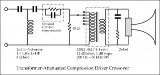
Here's the HF crossover for the compression driver, using a minor variation of the Klipsch and ALK crossovers.
The transformer (or autoformer) has some interesting advantages compared to an L-Pad:
1) The load as seen from the HP filter falls in very narrow range between 8 and 10 ohms, no matter what the compression driver is doing (the transformer impedance ratio is the square of the turns ratio). This essentially gets rid of the interaction between the triple impedance peaks (induced by the horn cutoff) and the crossover. The crossover is so insensitive to the compression driver it makes very little difference if the driver is 8 or 16 ohms; both look pretty much the same on the other side of the damping resistor.
2) The source impedance as seen from the compression driver is equally favorable. Instead of seeing the series impedance of the crossover and the optional equalizer, it sees the 10 ohm damping resistor divided by 16, which equals 0.625 ohms. This virtual source is in parallel with the amplifier source impedance, so the source impedance is actually well below 0.625 ohms in the passband of the crossover. The driver behaves very close to a multi-amped system in terms of source impedance (damping factor).
3) The transformer is not going to be particularly large, since there is no requirement to handle low frequencies, nor does it need to handle any more than 50 watts (under the most extreme conditions). The Klipsch autoformers are tiny, less than a cubic inch. I'll be asking Bud Purvine and Dave Slagle to make this transformer for the project - it isn't that different than prosound 70-volt distribution transformers, just a higher-quality application.
4) The inductance compensation (Zobel) is there to be nice to the transformer, giving it a resistive load beyond 100 kHz. This simplifies the transformer design, and makes it easier to get good square-wave performance. The Zobel also simplifies the crossover design, as well as making a gentler ultrasonic load for transistor amps with marginal feedback stability.
Attachments
- Home
- Loudspeakers
- Multi-Way
- Beyond the Ariel