One must be careful with "accelerated life" tests. They are great at fault detection and failure modes, but they are highly suspect for parameter stability assessment. The idea of accelerated life is to stress the part beyond its normal operating point. Changes seen in that kind of test will not necessarily happen under normal operating conditions.
Hello!
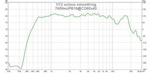
In the meantime I have done the first acoustic measurements with the 745Neo driver mounted to an 60x40 CD horn. Cut-off should be around 500-600 Hz.
I used a minimum cross-over with 6mu8 capacitor and an 22 Ohmes series resistor which is shunted with an 1mu2 capacitor. The driver itself has an 12 Ohm resistor in parallel. The rising impedance towards low frequency prevents the LF roll-off. No problem to correct this later on. What I want to show is the high frequency behaviour. The Earthworks M23 microphone is mounted in the middle of the horn near the plane of the mouth.
It seems that with the aluminium diaphragm there is a deep hole of around 6dB around 12kHz. Is this the mass break-up for Aluminium?
Would this HF behaviour be different with Be-diaphragm? Could anyone show a similar measurement with Be here?
Thanks!
Attachments
I've seen similar dips in other drivers. Is it real a hole, or is it the natural roll-off with the peaks beyond it just break-up?It seems that with the aluminium diaphragm there is a deep hole of around 6dB around 12kHz. Is this the mass break-up for Aluminium?
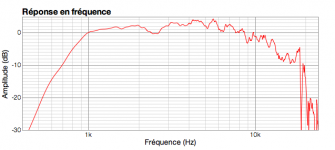
Could anyone show a similar measurement with Be here?
Here you go.
Attachments
One must be careful with "accelerated life" tests. They are great at fault detection and failure modes, but they are highly suspect for parameter stability assessment. The idea of accelerated life is to stress the part beyond its normal operating point. Changes seen in that kind of test will not necessarily happen under normal operating conditions.
In nuclear engineering in materials physics, they do this. At the Michigan Ion Beam Lab,(where my son is a staff research scientist) they do exactly this kind of thing to determine whether a potential product will hold up the a 10-20 year life in a nuclear reactor. It works.
I understand that taking to it too far would not show gradual changes, just like irradiating a sample to the point of dissolving would not yield data, but using appropriate parameters.....
Sounds like at least one good doctoral dissertation in acoustics to me.
Good job on the plots. Thank you Pano.
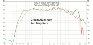
This is pretty much what I expected. The peak on the aluminum corresponds - as I understand it - to diaphragm breakup.
The Beryllium breaks up higher and differently. As a small aside, the hole above 2 kHz can be heard and is - in my view - a bit problematic. It does not look like much on the plot, but the ear is sensitive there. In my crossover I "padded" the response just above it to make this hole less noticeable subjectively.
Good job on the plots. Thank you Pano.
This is pretty much what I expected. The peak on the aluminum corresponds - as I understand it - to diaphragm breakup.
The Beryllium breaks up higher and differently. As a small aside, the hole above 2 kHz can be heard and is - in my view - a bit problematic. It does not look like much on the plot, but the ear is sensitive there. In my crossover I "padded" the response just above it to make this hole less noticeable subjectively.
The hole between 2khz and 3khz should be related to an impedance peak of the driver. Looking at the free air impedance helps here. I do not know if this peak is related to the back chamber of what else.
BUT, i think it can be quite reasonable handled with nearly current drive the CompDriver. You can find some hints here in the forum and i think from Jmmlc that a series resistor will help. Try at least a value of the self impedance of the driver. I have the same hole without the 15 Ohms resistor for my 16 Ohms driver.
HTH
Good to know, thanks!
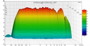
It would be interesting if you and Docali still have these measurements and could extract the impulse response. Might be nice to look at waterfall or similar graphs to get an idea of the aluminum breakup.
I am not sure if the measurement was loud enough. It could also be that the hole I measurement is related to the CD horn. I am not so familiar with waterfall settings in REW. I used the standard settings and adjusted only for the level. Here it is:
Attachments
That's for that graph.
From that all I see is an amplitude bump, it seems to decay at the same rate as everything else. When PierreQuiRoule rolls on home, maybe we can get yuo both the post the impulse files. There are some people here with very good analysis skills.
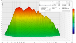
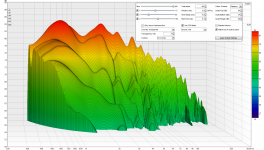
Hi Pano think "Window" and "Rise Time" is too long masking first wave front these frq, first graph below is example how raw 2426H into 2370a horn looks at default settings where second graph show some other settings that docali could use that would reveal much better how performance is.
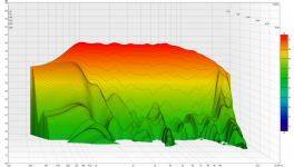
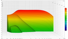
Learned a lot from wesayso how to use waterfall and settings to improve performance, basically when performance and correction is right speakers acoustic ringing resonances should really be more than 10dB down and if one can correct to levels in 20-30dB down sound gets impressive, as example third graph below show some trial to EQ correct 2426H/2370a combo, it show most domain resonances is now more than 20dB down but correction up at 23kHz area is somehow wrong and need attention to get that ringing away, forth graph is synthetic target curve for third graph and notice third and fourth graphs is smoothed 1/6 verse 1/24 at first plus second graphs.
Attachments
- Home
- Loudspeakers
- Multi-Way
- Beyond the Ariel