I don't hear those shimmery tweeter sounds in nature. Natural sounds just blend, I'm not conscious of the top end at all.
Very well expressed, Pano. Listening as an audiophile, I'm always conscious of the top end. As a musician...not so much. Nothing in real life sounds like an added-on tweeter.
I have memories of some amazing audio moments where something magical was made possible by very special tweeters, and the result seemed very close to reality. But such a system may only sound natural on few very special recordings. I can't live with that. I prefer to enjoy recordings of meritorious performances without having to endure distractions in the high frequencies.
When the RAAL tweeters were last in the system, they were being used to cover the region above the Radian 745NeoBe's unequalized rolloff, around 7 kHz. I am thinking about giving them a second chance, in which they would only be used from 14 kHz upward, extending the response of the equalized Radians. This region is really their sweet spot anyway, judging by the response curves. The other thing I would like to do differently is to place them in the same vertical line as the other drivers (previously they were next to [inside] the AH425s)...of course, I'll have to figure out some sort of appropriate mounting system.
And maybe an on/off switch for the RAAL, unless I find something that works for all recordings...wish me luck.
Gary Dahl
Gary I have the RAAL tweeters in a similar fashion. They are above a 320 Hz LeCleach horn operating from 9k upwards. They do add a realistic high frequency response and there is no integration issues with the horns below. I am actively driving them with an Aleph J amp.
Maybe all that is needed is a wider dispersion 'main' tweeter? You mentioned current tweeter 40deg at 10kHz, that's quite narrow. 90deg@10kHz is achievable without diffraction-slot....
I'm still attracted to the idea of directivity correction with an additional tweeter with just a bit of "super" in it. The AH550, and possibly one of the small AutoTech horns, look like good choices for the small-format Altec/GPA tweeters. The sonics (and EQ) of an ambience retrieval tweeter are somewhat different than the main, on-axis MF/HF driver, and Duke LeJeune of Audio Kinesis pointed out that the benefits are still there if the level is -6 dB below the main tweeter. So there's lots to play around with.
'Ambiance' tweeter needs to be correctly integrated. In your current situation, you have correct, flat-ish direct response, but the reflections arriving (preferably later than 10ms) at your listening position are severely low-pass filtered not just by the design of your speakers, but also by the stuff you put in your living room - sofa, rug, bookshelf, etc.
Now what Duke does is to block the direct response from the 'ambiance' tweeter and only correct the (semi)reverberant sound-field at the listening position - by making late arrivals spectrally correct and more dense, resembling a true reverberant field, as found in large spaces.
For testing you could try to redirect backwall reflection to the sidewall, that way you could make the 10-20ms arrival more dense.
Peter
Again very useful information. I wonder if that replaces the FT90H if anything. Perhaps you may know if the FT96H is an updated version or totally different?
Many Thanks
The FT96H has been available for many years next to the FT90H and is a lower end version.
The FT96H has a different membrane (see: http://www.rueegsegger-acoustics.ch/Website_3/Fostex-ACR.html), extends lower in frequency and has 1/3rd the magnet size. This not only gives a lower efficiency, but also means that the very soft compression that all drivers have starts at a lower level. (For most Alnico drivers this very soft compression is as benign as in single-ended class A amplifiers). In a multi-way system this very soft compression has to match with the other drivers, and the dynamic matching of different drivers is one of the challenging aspects of speaker optimization. One solution is to have the level at which this starts to be noticeable as high as possible, but then one needs larger magnet sizes with its associated cost. (Another solution could be to have a field coil version for one of the drivers and adjust the current for dynamic matching, but those field coil versions seem to be even more expensive.)
The FT96H matched quite well with the Audax paper midrange drivers and the Fostex full-range drivers and this was their primary use.
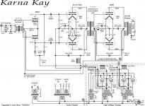
Here's the Karna Kay (posted previously) and the Symmetric Reichert amplifiers. As the name implies, it's basically a symmetric pair of Reichert SE 300B amplifiers, with the minor enhancement of split power supplies and a dynamic load for the driver section. For power-dissipation reasons, it's recommended that only one half of each 6SN7 is used for the driver, with the plate, grid, and cathode of the other half grounded. (Three 6SN7's and two 300B's per channel.)
Although the power supplies show the use of 6CJ3 damper diodes, the input+driver stage can use more common rectifiers like a 5U4 or 5AR4. Separate transformers for the 300B filaments are very strongly recommended, since rectification switch-noise from the HV secondary winding can capacitively couple into the low-voltage filament circuit and be audible as noise and "hash".
I no longer believe two-stage amplifiers are the way to go, so the Symmetric Reichert is a better choice for cost-sensitive builds. The simplest of all is the original SE Reichert, which is pretty much one-half of the shown circuit (minus the input phase splitter transformer). The voltages and currents are drawn from the measurements made by Thom Mackris on his recently completed split-supply Reichert SE 300B amplifier.
I'm pretty sure the Karna amplifier has higher ultimate performance, due to the more powerful (and linear) driver and the ability to enter and leave A2 operation without capacitor charge-discharge cycles.
Attachments
Last edited:
The situations where a model stands out, then becomes obolete is a fundamental aspect of life, is it not. There are the times when there is plenty and one sits on the fence, only to realise too late to buy and perhaps store the said item. I kept the ELS57 's gladly, as so many use them as the yardstick. Naturally that beats any other approach.The FT96H has been available for many years next to the FT90H and is a lower end version.
The FT96H has a different membrane (see: http://www.rueegsegger-acoustics.ch/Website_3/Fostex-ACR.html), extends lower in frequency and has 1/3rd the magnet size. This not only gives a lower efficiency, but also means that the very soft compression that all drivers have starts at a lower level. (For most Alnico drivers this very soft compression is as benign as in single-ended class A amplifiers). In a multi-way system this very soft compression has to match with the other drivers, and the dynamic matching of different drivers is one of the challenging aspects of speaker optimization. One solution is to have the level at which this starts to be noticeable as high as possible, but then one needs larger magnet sizes with its associated cost. (Another solution could be to have a field coil version for one of the drivers and adjust the current for dynamic matching, but those field coil versions seem to be even more expensive.)
The FT96H matched quite well with the Audax paper midrange drivers and the Fostex full-range drivers and this was their primary use.
It still remains, that perhaps it is better to design, so that a supertweeter is not required. I like the idea but probably for quasi sentimental reasons. Seem closer to the physics than ribbons, but does that matter in the end.
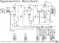
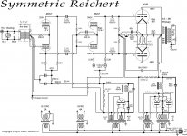
Updated schematics for the Karna Kay and Symmetric Reichert amplifiers. Voltages and currents are based on measurements of the Thom Mackris Reichert SE 300B and the existing Karna amplifiers.
Attachments

Last edited:
Lynn,
Given that you have the coupling transformer for the 5687 already in place in your amp, and presuming that your switch to capacitor coupling with the substitution of the 6SN7 is because of the 6SN7's higher Rp, have you considered another octal member of the family like the 6BL7?
Where the 6SN7 has a mu of 20 and Rp=7700 ohms, the 6BL7 has a mu=15, Rp=2150 which compares favorably with the 5687's mu=~16 and Rp=3000.
It just seems a shame to give up the xfmr coupling you already have, to return to coupling caps.
I myself presently run a 300b amp with a 6SN7 front into a 6BX7 cap coupled into the 300b, and this octal family member 6BX7 really isn't bad.
You're going to have to bore out a larger hole to switch to mounting an octal socket for the nine pin anyway, so perhaps some experimentation wouldn't be too large an endeavor? The 6SN7 and 6BL7 (& 6BX7) all have the same pin-out, BTW.
I've been collecting this octal family myself for some years. I think I've got a few, so if you need a pair of 6BL7's to try out let me know.
Chris
Well, it all depends on the spectral characteristics. One of the unusual aspects of the 45 and 300B is extremely low high-order spectral content; it's almost entirely 2nd harmonic, about 20 to 30 dB lower 3rd harmonic, and 4th and higher vanishing into the noise around -120 dB. Unfortunately, the 2A3 isn't quite as good in terms of high-order harmonics.
As a group, the IDHT's are good, but nowhere close to what DHT's can do. The 6SN7, and the direct predecessors like the 6J5, 6P5, 6C5, etc. are in a special low-distortion group (looking at the upper harmonics). The performance of the 5687/7044/7119 family is better than the 12AU7 and 6DJ8, but that isn't saying much.
I don't know if the bigger variants of the 6SN7 like the 6BL7 and 6BX7 are as clean; I heard a few years back that they weren't, but my info could be wrong. It all depends on the spectral info ... how fast the harmonic structure falls away. Plenty of tubes have harmonics out to the 10th and 11th harmonic, and they tend to sound more colored and grungier than the crystalline sound of the DHT's.
What surprising about a well-done DHT amplifier ... and I include the Reichert here ... is they sound radically different than traditional Fifties-style tube amps. The old amps have a grungy, somewhat dirty sound compared to a modern, well-designed transistor amp, although the tone colors from tube amps are better, and sometimes a lot better.
By comparison, a well-designed DHT amplifier with a low-distortion driver section is more transparent than even a really superb transistor amp, which is quite surprising to people expecting to hear Marantz, McIntosh, or Dynaco levels of grunge. And the tone colors are the most vivid of any type of amplifier ... it makes system tweaking pretty much unnecessary, since you're already there. All the speakers have to do is deliver flat response, have a competent crossover, and be reasonably efficient.
But I did say "well-designed", which isn't true of most of the commercially available DHT amps seen and heard at hifi shows.
The trick with DHT amplifiers is having a driver stage that has less distortion than the final DHT tube ... and that means 60V rms (into a capacitive load) at very low distortion levels with very little high-order distortion content. Otherwise, nearly all the amplifier distortion is coming from the driver, which defeats the whole point of a DHT amplifier. If you're not hearing the DHT as it really is, you might as well buy an off-the-shelf transistor amp and save a lot of money.
So it all comes down to the performance of the driver and input tube. The 5687/7044/7119 input tube creates nearly all the distortion above 5th harmonic in both the Amity and Karna amplifiers, so it's going to get replaced with the spectrally cleanest tubes I can find. Although it's possible to build an all-DHT amplifier, chasing out microphonics is a major hassle, and I still have reservations about the performance of the input-to-driver interstage transformer. That's a part of the amplifier where additional capacitive loading is very undesirable; it limits slew rate, and increases HF high-order distortion because of the elliptical load-line presented to the anode of the tube.
All-transformer-coupling is conceptually elegant, but it comes down to the performance of the tubes driving those transformers ... how much capacitance do they see, how linear is that capacitance, how much hysteresis does the interstage have as it transits through the zero-current region, and does that hysteresis interact with the odd-harmonic distortion of the tube?
Granted, I'm not a big fan of capacitor coupling. I don't understand why capacitors have weird colorations, but they're certainly audible on a high-resolution system, and if they're bad enough, can sound like problems in the tweeter section, or crossover errors. Subjectively, the really old-school wax-and-paper types, with solid foils, seem to have the least coloration. Again, I don't understand why, but that's what I hear.
Part of the reason for these musings is listening to Thom's latest split-supply Reichert SE 300B amplifier, which is nearly as transparent as my amp, although not quite as powerful. Yet the circuit is a perfectly mundane set of RC-coupled 6SN7's driving, once again, a 300B. But the operating points are very well-chosen, and it says a lot about the performance of the 6SN7 that it can drive a 300B and a 15K plate-load resistor at the same time, with only a modest 10 milliamps of operating current.
Last edited:
Always appreciate you sharing, Lynn.
If the input/driver B supply transformer has not been locked in, could you consider using the 5687 transformer to couple 6BL7 to the output stage and then DC couple the input tube to the driver?.. Rk is already bypassed, just seems a matter of B volts to make it work.
.. unsure about max vRMS level of the 5687 xfmr, but Rp 6BL7 is not so dissimilar to the 45, maybe use that one instead - anyway, you'd get the idea.
L.H
Last edited:
DC coupling is not attractive in a differential amplifier. Small differences in gain in the input pair (typically 5%) result in large differences at the driver grids. For example, if a 6SN7 with its gain of 20 has a mismatch of 5%, that's a 10-volt difference at the grids of the driver tube ... far too much. That alone uses up much of the bias range of the driver tube, resulting in grossly unequal current flow.
A center-tapped audio-grade choke would remove most of this, since the load at DC is only a few hundred ohms. But some voltage differential would remain, unbalancing the driver stage, which may in turn result in asymmetric distortion spectra from the driver pair. If the grid voltages are different, that means the two sections trace different load-lines, and the even-order harmonics are only partially cancelled. Worse, the DC imbalance randomly drifts, resulting in distortion spectra that change slowly with time.
An interstage transformer or RC-coupling completely removes the problem, letting the driver find its own balance, instead of being pushed to one side by the input pair.
I'm curious to see what the harmonic distortion spectra of the 6BL7 and 6BX7 are. They might be as good as the 6SN7, but I am a little doubtful. Very few IDHT's have distortion as low as the 6SN7 series ... which is several times lower than the more common 12AU7 and 6DJ8.
I'm not in the "euphonic distortion" camp; I want to see high-order distortion as low as possible. I'm OK with 2nd harmonic; audibility is low, and more than 90% is cancelled by differential amplification. 3rd harmonic is not as nice, but if it's more than 20 to 30 dB down, that's not so bad. 4th harmonic, similar to 2nd, and mostly cancelled by differential amplification. The real trouble starts with 5th harmonic; this is dissonant and not cancelled by differential amplification.
Going further, the number of IM distortion terms is a high-order function of how many THD harmonics there are; put another way, an amplifier with a simpler harmonic structure will have lower IM distortion, which can be viewed as a program-modulated noise floor.
Unfortunately, most simple tests of THD in tubes are dominated by the 2nd harmonic, and vacuum tubes tend to have roughly similar levels of 2nd harmonic distortion unless they are outright defective. The real differences are in the high-order harmonics (5th on up), and different types and brands can differ by more than 20 to 30 dB, which is not a small difference. Surprisingly, changing the operating point only shifts the overall spectra up and down by a few dB, but changing type or manufacturer exposes 20 dB differences.
And yes, this is audible when there is no feedback to mask the differences. One of the biggest benefits of feedback, aside from better measurements, is washing out the differences in tube types and the sonics of passive parts. 20 dB of feedback, a typical feedback ratio for the Williamson, Dynaco, and Mullard circuits of the Fifties, removes most of the differences in drivers and input tubes. Measures good, parts don't matter as much, who's complaining?
Last edited:
SE drive via IT to PP grid is not a consideration?
It does balance even to odd order harmonic levels more favourably, proportional - and I wonder how much of that which you like in the R.300BSE could be attributed to this.
That is to say the 'spectra' of 2, WRT 3H has not the cancellation of (our lovely) 2H as is the case with PP.
With the right tubes which have lower higher order content, best of both worlds?
Of course, good high level (vRMS) IT's like this aren't exactly run of the mill..
--
I really appreciate the edit function !, most of the time I know what I;d like to say but don't know how to type it")
L.H
It does balance even to odd order harmonic levels more favourably, proportional - and I wonder how much of that which you like in the R.300BSE could be attributed to this.
That is to say the 'spectra' of 2, WRT 3H has not the cancellation of (our lovely) 2H as is the case with PP.
With the right tubes which have lower higher order content, best of both worlds?
Of course, good high level (vRMS) IT's like this aren't exactly run of the mill..
--
I really appreciate the edit function !, most of the time I know what I;d like to say but don't know how to type it
L.H
Last edited:
This is very very difficult for the transformer builder. It is essential that the SE to PP conversion has good control of phase at least through 20 kHz, and 50 kHz is better. For differential cancellation to work, the amplitudes and phase must be tightly matched. If the phase drifts apart by more than a few degrees, the even-order harmonics start to increase rapidly (see a vector diagram to see how small a level or phase mismatch starts to affect cancellation).
This would be benign if it were constant with level and frequency, but phase-match is very difficult if the transformer has a high-impedance source (like a tube anode), a load that is mostly capacitive, and a SE -> PP conversion is also required. If the IT is symmetric (PP -> PP), it's still difficult thanks to the high impedances, but the outcomes are generally better. I'd like to see 5 degrees of phase match on the paired secondaries at 50 kHz, but that's probably asking too much.
Setting aside difficulties of transformer design, there's the matter of what happens when one of the 300B grids momentarily draws current (entering the A2 region). If the driver tube is single-ended, it's fine if the current is running high - this helps one of the 300B's. But in the other direction, the driver is approaching cutoff, and current through the driver tube is approaching zero. So the amplifier is A2 in one direction only, which I have to admit is the same as an IT-coupled SE amplifier. But it would be nice if the PP amplifier was equally capable in both directions ... it's the output section that costs the most, after all.
If ... and only if ... a good SE -> PP interstage transformer could be made, a SE 300B -> interstage transformer -> PP 300B amplifier would have good performance (although a little microphonic from the driver tube). I've seen circuits that work this way, but I'm not too sure the HF performance is very good, because the requirements for the IT are so severe. In the midband, though, the harmonic spectra would be nicely balanced, with the driver giving just a touch of 2nd harmonic at moderate levels, and keeping high-order harmonics to a minimum.
As you can tell, I'm concerned about distortion spectra that vary with frequency (or level). I strongly suspect the ear adapts quickly to a given spectra (providing it's not too dissonant) and thereafter ignores it. But ... if the spectra varies with frequency, in particular, getting worse with higher frequencies, I'm pretty sure it will sound like the amplifier is spectrally imbalanced, even though it measures flat.
Last edited:
I've heard two versions of Bud's IT for this and both sounded more than acceptable (++), compared with two Fe cored Lundahl types designed for high level split. Both for DHT driver Ip 20-25mA and Rp ~2k.
Its not a secret that he claims to 'do this and that' with his magnetics, and I'm sure that you're familiar with this.
How that correlates to measurements WRT critique, I cant say - but subjectively it seems to work - if only compared with the LL which sounded poorly (and I mean that) by comparison.
Seems to me that its fairly unchartered waters, but I did get some soul back from running (away from) PP IT drive PP.
In the end I suspect that we all get to where we're supposed to go, and subjectivity will always win - to the point at which it is a 'dead-end' WRT blogs and only building to individual taste will prove satisfying to the individual.
Thanks, Lynn - you're my favourite 'post to read person', here.
L.H
Last edited:
I have to admit an amplifier with three 300B's glowing on the top deck would look very cool. Plus, the spectra from the driver and output would match ... something to be said for that.
The DHT driver(s) certainly have a lushness that just isn't there for IDHT drivers ... it's like the DHT sound squared, and makes the hassles with the filament circuit worthwhile.
I very much appreciate your subjective results with high-level SE -> PP conversion. Class A PP amplifiers with very clean spectra sit right on the knife-edge of being a little too sharp, compared to their SE brothers. They are more transparent than nearly any transistor amp, and are unforgiving of poor-quality source components. Oddly enough, "bad" recordings are very listenable, since the crud floats above the music and doesn't contaminate it. The crud sounds like little discrete specks of noise instead of a roar of distortion.
Isolating the power supplies went a long, long way in getting rid of the usual PP sound. The ripples in current on the power supply of a Class A PP amplifier are very much like the output of a balanced AM modulator. By getting rid of cross-coupling from stage to stage, just about all of the hash goes away, and transparency goes way up.
Last edited:
Our adventurous friend Zigzagflux has posted not just photos, but detailed measurements of his version of the Karna Kay amplifier ... although he came up with the RC-coupled input section first! As you can see, performance is in a different class than most SET or PP-pentode-with-feedback amplifiers.
What I find remarkable is a zero-feedback amplifier outperforming a "Golden Age" tube amp with 20 dB of feedback. That says a lot about the inherent linearity of the input, driver, and output tubes. This is not a Williamson, Marantz, Dynaco, or Mullard architecture, and doesn't sound like them.
The Symmetric Reichert, though, is pretty close to the Acrosound circuit, just with better tubes and an improved power supply.
I see the speaker-amp is an integrated combination. Although both fit into industry-standard interfaces with respect to impedances and drive levels, they sound best together. Another advantage of (roughly) following standard interfaces is quick comparison with conventional home-theater and audiophile equipment. By flipping four DPDT switches on the crossover (which isolate the grounds of the two systems), I can quickly change from 5.1 channel HT to 2-channel audiophile listening, with completely separate chains of amplification and signal sources.
P.S. Thanks, Ludwig Haus, for your valuable comments! You've given me some good things to think about, particularly from the perspective of subjective balancing of the overall system. As we see from Zigzagflux's measurements, the driver tube now looks like the limiting factor in the overall amplification system.
Last edited:
OK, let's look at Ludwig Haus' proposal with a clean sheet of paper. The obvious choice for the input tube is half of a 6SN7 or all of a 6J5, 6P5, 6C5, or similar single triodes. (Some octal, some five-pin, why not just parallel the sockets?)
This is RC-coupled (with resistor-isolated current source) to a small DHT driver tube, most likely a 71A, 45, or one of the interesting European tubes. Presumably the operating current is between 25 and 30 mA, and the anode between 250 and 300V.
The SE -> PP interstage is going to be a special-purpose part, so let's go over what's needed. To match the HF phase of the twin secondaries, one of them will probably need a small amount of balancing capacitance, most likely a small value of silver-mica cap.
My experience with parallel-feed has not been positive, so let's ask for the core to accept 30 mA of polarizing current, so it's going to need to be air-gapped and somewhat larger than a PP interstage. It also has to handle another 20~25 mA of peak current in one direction without saturating.
The driver tube has to linearly drive the 80V bias of the 300B's, and will swing from 250V down to 120V (it will swing further in the other direction, but with decreasing current). The other aspect is the capacitance of the twin 300B's ... about 60~70 pF each. The additional capacitance of the transformer will probably be around 30 pF as seen from the anode of the driver.
If the ratio is 1:1+1, then the driver see too much capacitance, probably 150 pF or more. This is the downfall of PSE architectures ... the driver sees too much capacitance, the amplifier loses slew rate and HF distortion increases, and the amp sounds dull and congested at high frequencies.
If the ratio is 1:0.5+0.5, then the driver has to linearly swing peaks of 160V, which is similar to driving an 845 (which is nearly impossible).
So a ratio of 1:0.707+0.707 looks like a good compromise between required voltage swing and additional capacitance presented to the driver-tube anode. At the expense of a bit more capacitance, 1:0.8+0.8 asks a bit less voltage swing, and 1:0.625+0.625 is more favorable in the direction of less capacitance. I think we can see that 300V on the anode would be a good idea ... we're going to need that voltage swing if we'd like to prevent the entire amplifier clipping at once.
Last edited:
I've heard a fair bunch of PSE amplifiers, and they seem to exaggerate the faults of SET amplifier ... which is something SETs don't need at all. The ones I've heard were murky and dull, and the worst were PSE pentodes-connected-as-triodes.
This is also what I hear, in milder form, with many commercial SET amplifiers. The driver just isn't up to the job, so you never hear the beauty, clarity, and tonal vividness of the power tube. It justs sounds murky and muddled. That is not the sound of SET; it's taking the corner-cutting design practices of conventional PP-pentode amplifiers and applying it to SETs, and you get the worst of both worlds. (The lack of power of SETs and the congestion and haze of PP-pentode.)
Way back in the Nineties, Arthur Loesch and I discussed this problem at some length as the Winter CES in Las Vegas. We both agreed that nearly all amps ... transistor, PP-pentode, and SETs had poorly designed driver stages that resulted in poor HF behavior and congestion at high levels. Drivers, as a rule, need several times as much current as typically used in commercial designs, and attention needs to be paid to linearity into capacitive loads. This is usually ignored and a just-barely-good-enough driver is used.
There even expensive amps that use a 12AX7, with its 1 mA of standing current, to drive PP EL34's or KT88's!!! Needless to say, they sound bad ... really bad. Part of the reason for the funky, old-fashioned sound of the Dynaco Stereo 70 is the very mediocre driver/phase-splitter tube, which really can't drive the PP EL34's at all well. A simple parts replacement with good octals completely transforms the sound of the amplifier (and improves measured performance).
Capacitance is a big deal at the high impedances seen in vacuum-tube amplifiers. And just throwing in a cathode-follower as a buffer doesn't solve the problem; a cathode follower is merely using 100% local feedback, and the inherent harmonic structure of the distortion is still there, just attenuated by the gain of the tube.
Better to keep capacitive loads to a minimum, and when unavoidable, use a powerful driver that maintains linearity into that load. At least Miller capacitance is linear, which is more than can be said of MOSFET capacitance, which is orders of magnitude higher and is also nonlinear. But it still has to be addressed by adequate driver design.
Last edited:
- Home
- Loudspeakers
- Multi-Way
- Beyond the Ariel