Phantom center fix thread is here
http://www.diyaudio.com/forums/multi-way/277519-fixing-stereo-phantom-center.html
http://www.diyaudio.com/forums/multi-way/277519-fixing-stereo-phantom-center.html
It hasn't been covered in any detail, really. The original goal was a nominal frequency of 700 Hz. We were aiming for a curve shape somewhere between Butterworth and Bessel. I began with cookbook part values and made measurements. With the woofer, the acoustical rolloff was way too high. I tweaked the values until everything added up to the nicest-looking combination of flat passband response and smooth rolloff. Measured crossover frequency ended up closer to 900 Hz. I found that I could get a much nicer response shape if I didn't try to move it lower so I left it alone.
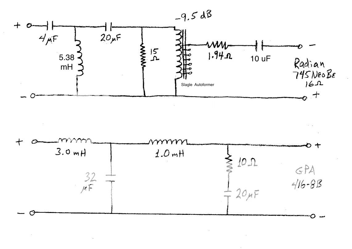
The HF section was at first approached in a similar manner. The original crossover was created with the regular Radian 745-PB driver (ferrite magnet, aluminum diaphragm). It utilized a 3rd-order filter, Zobel, swamping resistor and Slagle auto former attenuator. Response was quite flat to 17 kHz, but I must admit that I wasn't really satisfied with the tonal character of the upper octaves.
When the 745NeoBe became available, I snapped up a pair in hopes that the beryllium diaphragm's performance advantages would result in a more pleasing result. Without adjustment to the crossover, results were mixed. Its lower range had somewhat less output, and there was a broad peak around 4-5 kHz. Above this, response rolled off in a quite linear manner. For some time, I used the RAAL Lazy Ribbon tweeter to cover the top end.
In offline conversations, Pierre and I compared notes about the integration of the compression driver and ribbon. Eventually, he reported optimum results using passive equalization of the 745 driver, sans the ribbon. He shared his schematic with me, but since our autoformers (and woofers) were different, the actual values of the parts didn't apply in my case. I took my speakers outdoors so I could make some clean measurements (at least when the neighbor's lawn mower wasn't running...) and worked to optimize the crossover as best I could.
After some reworking, I was really pleased with the results on the LF section. As for the HF section, Pierre's approach brought about remarkable results. After optimizing part values for my system, the simple circuit was able to simultaneously lift the LF droop in the CD's response, level the peak, and flatten the previously rolled-off HF region. Final response went smoothly to somewhere around 14 kHz or so. Yet I wan't quite satisfied with the way the LF and HF sections summed; there was a wrinkle in the response that I still believe could be ameliorated by raising the turnover frequency of the HF section.
I wasn't able to improve it with capacitors on hand, and didn't have inductors of suitable value for further experimentation, so I brought the system inside for a listen, not knowing what to expect. Wow, just wow. Even without the last top half-octave, the entire upper half of the frequency range sounded so beautifully natural, and the imaging was greatly improved. The drivers integrate with delightful seamlessness.
It wouldn't hurt my feelings if it gets better than this (!), but it exceeded my expectations for this stage of the project, and is definitely a plausible stopping point. As an amateur hobbyist speaker builder, I am frankly pretty darn proud to have reached this level of musical realism, with the help of Lynn, Pierre and others on this board. But there is most certainly room for improvement. I look forward to taking it further, and benefiting from the contributions of other DIY enthusiasts.
In its current form, the crossover is the best I have been able to do using the combination of drivers, enclosures and parts on hand. It is certainly not optimized for any other combination of drivers and enclosures. Anyone building this project should expect to make their own measurements and adjustments--it was most definitely needed in my case.
Gary Dahl
That is a very interesting report. I think the process points out the importance of a well-designed crossover to get the most out of the drivers and configuration.
What is the advantage of using the autoformer? Is it custom made or off the shelf?
It would be very interesting to see what the modifications from Pierre do to the CD’s response (modeled and measured).
Regarding subs for me the question is rather if 4 10”s in an average room (25-36m2) work better than two 15”s integrated with the main speakers. What is the max recommended low pass frequency for multiple subs (given certain room dimensions)?
S.
The combination of the autoformer and the swamping resistor serves to isolate the crossover from the large impedance peak just below the horn's LF limit; in this case, about 350 Hz. With the swamping resistor in parallel with the the driver/autoformer combination, the crossover works into a relatively flat impedance. The large difference in sensitivity between the woofer and the driver calls for a significant amount of attenuation of the latter. To my ears, autoformer attenuation (of compression drivers) brings a smaller sonic penalty than that of resistors.
There are other ways to do this, especially with the equalization. Martin has reported excellent results using equalized crossover circuits without autoformers. I haven't tried any of this, but have an open mind.
Pierre's modification consists of the resistor-capacitor combination between the autoformer's output and the driver; in the original it was just a wire. He described to me the general effect of varying the values but left me to determine the optimum combination for my circuit. Sorry to say I didn't save the curves I made during the process; because of circumstances I had to work fast, and honestly I didn't expect my results that day to be as sonically successful as they were.
Undoubtedly someone with technical chops beyond mine will take this design to greater heights.
My autoformers (Slagle) were inadvertently made with a couple of missing taps, so I guess they're really not off the shelf. Luckily, the missing taps aren't of consequence to me.
Gary Dahl
When using LTSpice to simulate a cross over, how should one model the driver? I just measure the Z with a suitable meter at the nearest possible point and enter the value as an R in the model. (in my case it was 1000Hz). I'm a learner driver but it seems a really nice way to tune the xo, eg for Pierre's add on. But then the Z of the driver is probably different when this takes effect.
I suppose you could do it in Spice, but there are easier ways. Programs like XSim or PCD are meant for simulating passive crossovers. And they are free.
To get accurate results, you should have impedance measurements and FR measurements to enter into the sims. Doing that, the results are pretty accurate.
To get accurate results, you should have impedance measurements and FR measurements to enter into the sims. Doing that, the results are pretty accurate.
I modelled everything in LTSpice. Ultimately the accuracy is limited by my poor models of the horn and autoformer. Still, simulations were useful for understanding the effect of various changes to the crossover configuration.
Gary is a brave man purchasing the Radian Neo's as soon as they came out. I waited and bought mine only after reading his positive review.
Pierre
Gary is a brave man purchasing the Radian Neo's as soon as they came out. I waited and bought mine only after reading his positive review.
Pierre
Of course I made impedance curves and frequency response measurements of my drivers in their horns and enclosures before commencing development and optimization of the crossovers. But I have no skills in modeling, so all I could do was build and make measurements of the real thing, then make repeated cycles of further modifying and measuring.
Dave Slagle's LTSpice models of crossovers using autoformers with swamping resistors made a great resource when I was working on the original crossover. It would be interesting to see the effect our EQ in his model (I didn't ask). But at least it was very easy to see the effect of part value changes on the actual speaker's response.
Gary Dahl
Not having a FR curve and an accurate impedance curve means that any crossover design is just a shot in the dark. The dc resistance of a voicecoil is not going to tell you what you want to know. Today with many open source free software programs, an inexpensive measurement microphone and a good sound card all of this is now possible for many diy enthusiast for measurements that can give a much better result than the old book perfect network designs. You do have to spend a bit to really do an accurate and well thought out network. If the manufacturer of the speaker components gives accurate impedance curves and FR plots you are half way home with all of this.
ps, once we add a horn to all of this you better be able to make real measurements or you'll never get things correct.
ps, once we add a horn to all of this you better be able to make real measurements or you'll never get things correct.
Last edited:
Well spoken, Kindhornman -- couldn't agree more.
If only!
Gary Dahl
If the manufacturer of the speaker components gives accurate impedance curves and FR plots...
If only!
Gary Dahl
ps, once we add a horn to all of this you better be able to make real measurements or you'll never get things correct.
Fully agree.
Anybody here tried Karlson K15 enclosure for midbass/low mid 80-500hz ? There are mixed reports about that box and I never heard one .There is a pair locally which I can grab for testers and I can either stick 515B or 416 in them and use altec 288c in radial horn above.
Rgrds, W
Rgrds, W
If either of you guys want to post your impedance files here, I'll be glad to room them thru a couple of simulators and show the results. Of course we'd need to know the impedance at the primary of the transformer for the horn.
Should be easy enough to plot the actual filter function and show a graph.
Should be easy enough to plot the actual filter function and show a graph.
passive to active
Any of you guys following this, ever consider just dumping this passive crossover idea, and going to an all active 3 way ?
I just can't encourage you enough to try an all 18 db/octave, analogue, active crossover.
I truly believe there are enough smart, filter theory guys here, to come up
with a circuit for this.
I expect the next thing I will read about is how much extra money all these additional amplifiers will cost. Well, yes, they do. Put your Class A SET on the
compression drivers where they belong. Heck, Class D can work for deep bass just fine, and then pick something you like for the Altec 416-8B. Something real nice in the 60 watt range.
If you really, really, want the best sound possible, this is the way to go !
Scott,
The reality is by the time you look at the cost of the autoformers and the cost for good perfect lay inductors and 100v polypro caps you could build and active network for the same or less I imagine. You can purchase inexpensive active boards on Ebay and for the cost of some opamps and resistors you have a Saleen Key network.
On this thread it all seems to be about retro designs, from the amps on up.
I just came across a box of large perfect layer Erse coils I've had and I can only imagine what they would cost today.
On this thread it all seems to be about retro designs, from the amps on up.
Guilty as charged, officer! A long-time offender too, all the way back to the first Ariels in 1993, which were auditioned with a rusty old Dynaco Stereo 70, the Reichert Silver 300B, the Audio Note Ongaku, and bunch of other "retro" electronics.
To repeat: These speakers, along with the Ariels, are designed for triode enthusiasts. They may, or may not, work with other types of amplifiers. Since I'm a systems guy, I design the amplifier and loudspeaker as a complementary pair to create a certain type of subjective experience.
As it is, the Ariels spend 90% of their time connected to a Marantz home theater receiver (AV8003/MM8003), where they're just fine for casual listening (lossy-compression movies, TV, and Internet audio). With the flip of four DPDT switches, the Ariels go over to the all-triode 2-channel system with the Burr-Brown PCM-1704 DAC (CD's, SACD's, and 96/24 downloads). I can compare an all-transistor to an all-triode signal path in a few seconds, by moving the source from the Blu-Ray player to the CD transport.
The new speakers are going to be connected the same way.
Last edited:
Guilty as charged, officer! A long-time offender too, all the way back to the first Ariels in 1993.
To repeat: These speakers, along with the Ariels, are designed for triode enthusiasts. They may, or may not, work with other types of amplifiers. Since I'm a systems guy, I design the amplifier and loudspeaker as a complementary pair to create a certain type of subjective experience.
Lynn, I saw you coming down the line fast, so I jumped off quick with a bit of poetry. These people do not see the light.
I exclaimed Great Scot! as Sherlock Holmes might say to his companion, dear Watson, trying to give him advice on 'watts' new and 'watts' not with unproven hypotheses.
Why does a 3 stage solid state amp sound better than a 6 stage. The old retros optimally revised and updated with modern superior material are having a new lease of life, but this really splits the audiophiles from the sound reinforcement and other professional users even more. We are in their territory, but using it as appropriate to our meet our own audiophile requirements, but our requirements and tastes are quite different.
Last edited:
- Home
- Loudspeakers
- Multi-Way
- Beyond the Ariel