I'd love to hear a good EL84 PP amp on my horns. Currently I am using PP 300B's. They sound great, but I would be happier if they were quieter.
This summer I will build Gary Pimm's 20-watt class A solid-state amp design. I liked the way his own unit sounded with my speakers. It will be interesting to find how it compares with my tube amps, which were out of service at the time.
Gary Dahl
Solid state done right is IMO the way to go, and dead quiet
The topology has been posted in this thread, but I'm not yet sure when (if ever) I will post a crossover schematic with part values. Mine won't really even be finalized until late summer when I get a chance to move my speakers to a place where I can set up an appropriate environment for getting cleaner measurements. Also, my part values wouldn't provide the same results in someone else's system anyway (different cabinets, room, etc.), so they would be of limited use.
Thanks.
Can you please repeat the topology and the crossover frequencies?
Hi Joshua_G,
Here is a picture of the speakers in their current form:
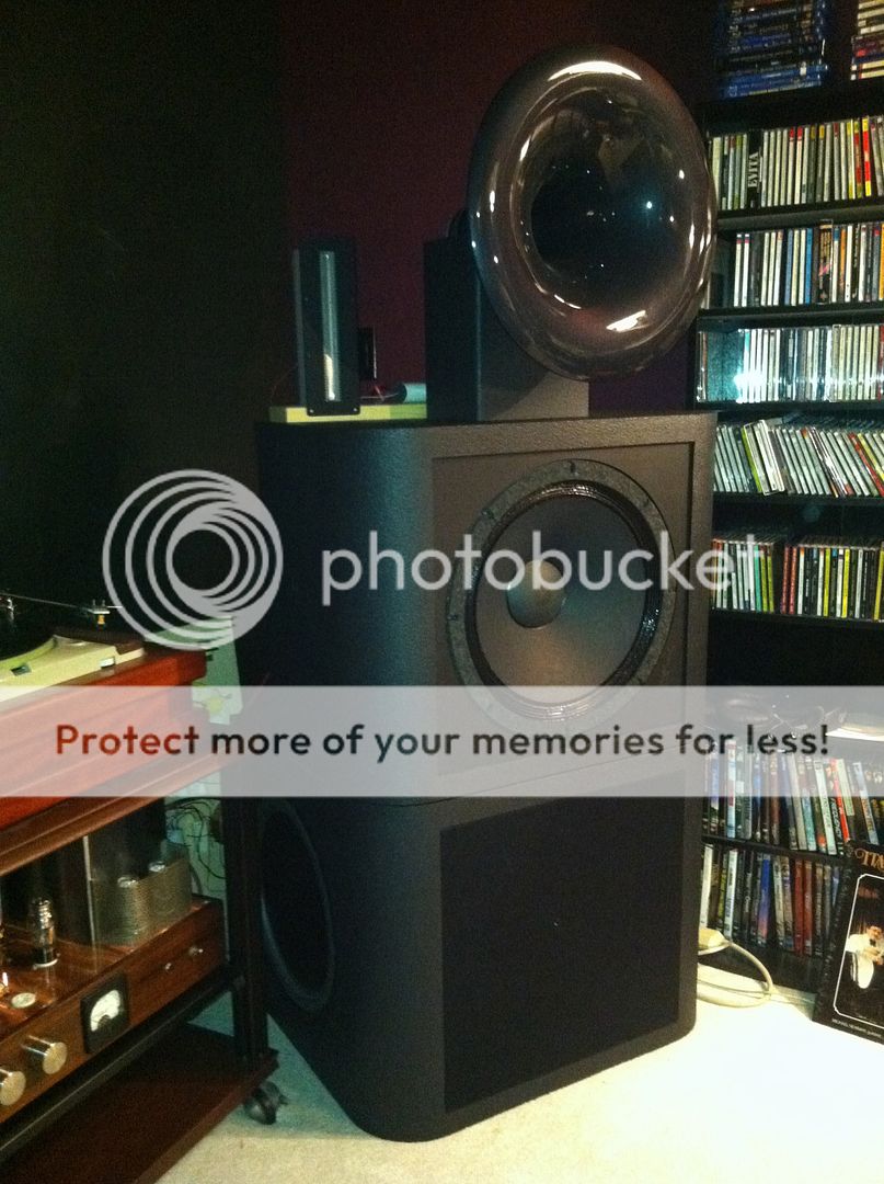
If the picture looks "squished," you might need to click on it. I don't know how to fix it.
Here is a description:
1. RAAL Lazy ribbon, 2nd order high pass at ~8 kHz, 10-ohm tap of tweeter connected to -9.5 dB tap on Slagle autoformer.
2. Radian 745NEO/Be (16 ohm) driver, Azurahorn AH425, 3rd order high pass at ~700 Hz, connected to -17.5 dB tap on Slagle autoformer with 35-ohm swamping resistor.
3. GPA 416-8B Classic Series (alnico), 3 cu ft sealed enclosure, 3rd order low pass at ~700 Hz, Zobel circuit, -3 dB at 61 Hz, attenuation-band notch filter at about 1,500 Hz.
4. AE TD15H-4 plus two AE PR15-700 passive radiators (1 on each side of cabinet), separately powered by plate amp. Enclosure is 5 cu ft, tuned to 23 Hz.
The crossover frequencies (and even their orders) are actually somewhat different than shown above when the acoustical response is taken into account. The transitions sound quite seamless but I won't be quite sure what is really going on until I can get some cleaner measurements. For example, the the rise in the upper end of the 416's response works against its LP filter, resulting in a higher-than-predicted cutoff point and a gentler slope. Meanwhile, the 745's beryllium diaphragm has a bit of droop below 1 kHz, so the two curves sum pretty nicely. I want to get some cleaner measurements so I can see if further adjustments are of value.
Gary Dahl
Here is a picture of the speakers in their current form:
If the picture looks "squished," you might need to click on it. I don't know how to fix it.
Here is a description:
1. RAAL Lazy ribbon, 2nd order high pass at ~8 kHz, 10-ohm tap of tweeter connected to -9.5 dB tap on Slagle autoformer.
2. Radian 745NEO/Be (16 ohm) driver, Azurahorn AH425, 3rd order high pass at ~700 Hz, connected to -17.5 dB tap on Slagle autoformer with 35-ohm swamping resistor.
3. GPA 416-8B Classic Series (alnico), 3 cu ft sealed enclosure, 3rd order low pass at ~700 Hz, Zobel circuit, -3 dB at 61 Hz, attenuation-band notch filter at about 1,500 Hz.
4. AE TD15H-4 plus two AE PR15-700 passive radiators (1 on each side of cabinet), separately powered by plate amp. Enclosure is 5 cu ft, tuned to 23 Hz.
The crossover frequencies (and even their orders) are actually somewhat different than shown above when the acoustical response is taken into account. The transitions sound quite seamless but I won't be quite sure what is really going on until I can get some cleaner measurements. For example, the the rise in the upper end of the 416's response works against its LP filter, resulting in a higher-than-predicted cutoff point and a gentler slope. Meanwhile, the 745's beryllium diaphragm has a bit of droop below 1 kHz, so the two curves sum pretty nicely. I want to get some cleaner measurements so I can see if further adjustments are of value.
Gary Dahl
Hi Gary,
Thank you very much.
The picture looks fine.
I get that the crossovers are tuned to both the speakers and the listening room, yet I needed a starting point, which you graciously provided.
Right now my mind and time are elsewhere (directing, producing and editing an indie documentary movie) and my finances are below zero.
But this is only right now, as some of us may know, the wheel turns…
Hi Joshua_G,
Here is a picture of the speakers in their current form:
~~~~~~~~~~~~~~~~~~~SNIP~~~~~~~~~~~~~~~~~~~~~
Gary Dahl
Hi Gary,
Your new speakers looks pretty darn sharp. You've always done very nice work and the pictures indicate that these speakers are certainly no exception!
Best Regards,
Terry
Some of it is mechanical noise from the power supply iron, which was scavenged from Lynn's discards. At the time, I was trying to build his design "on the cheap" making use of every recycled part I could come up with. I have another set of power iron waiting in the wings and will install it when I get a chance.
The rest of the noise is there because of imbalance between the output tubes. The circuit doesn't have a hum balance pot, making its noise level dependent upon the matching of output tubes. My current set of output tubes don't match as well as the ones I have had in the past, unfortunately. The "matched quad" has two tubes that match, and two that are off in opposite directions. If I use the matched pair in one channel, it runs silently (except for the power iron, of course), but the other channel is too noisy. Best results are obtained by splitting up the pairs. Or I could order more tubes, of course.
Lynn doesn't have the matching problem in his own amp because he has a special circuit for cancelling the hum...another good project for me in the future.
Gary Dahl
It's always good to have more projects.
")
The next DIY project on my horizon will be building Gary Pimm's amplifier design, the Solid-State Tabor (transformer coupled!)...... The iron for it should be ready by mid-summer.
Interesting - a variation on that theme is Susan Parker's Zeus which was developed about the same time. If my memory serves me Barbour's IEEE Spectrum article of 1998 suggested that well selected MOSFETs run at valve like operating points should be of similar linearity.
Ah - "The IRF822 was very triode-like in distortion yet suffered from a noise floor some 30 dB higher than that of the triode." (side bar on distortion Eric Barbour with John Atwood)
Last edited:
Yeah I dig Gary's speaks as well. Nice aesthetically even for a large speaker.
Below the Altec (as opposed to beyond the ariel), ever think of employing the single bass array concept to lessen room modes between the primary mode and schroeder frequency? For example a bunch of good but economical 15" woofers (Dayton reference series for example) in sealed alignment stacked vertically and placed appropriately horizontally. If you cross them low enough like gary's setup you could run them off an Inuke DSP6000, cheap and cheerfully while being able to employ LR transform on the stack.
Below the Altec (as opposed to beyond the ariel), ever think of employing the single bass array concept to lessen room modes between the primary mode and schroeder frequency? For example a bunch of good but economical 15" woofers (Dayton reference series for example) in sealed alignment stacked vertically and placed appropriately horizontally. If you cross them low enough like gary's setup you could run them off an Inuke DSP6000, cheap and cheerfully while being able to employ LR transform on the stack.
Last edited:
Hi, Elias! I set dipoles aside after considering the equalization requirements, which conflict with the intention to use the loudspeaker with low-power triode amplifiers. In particular, seeing the detailed equalization curves for Linkwitz's speaker at one of the RMAF shows really gave me pause. The woofers had 20 dB of boost EQ in the 30~300 Hz range, and the midrange had a M-shaped EQ curve with the left side of "M" having 8 dB of boost while the right side had 6 dB of boost. No EQ was required for the dome tweeter, of course, just a highpass filter.
The reason for the "M" shaped midrange curve was to counteract the baffle peak, which fell right in the middle of the mid's working range. That got me thinking a little more about the impulse response.
In an OB with a perfect driver, you see the impulse from the front of the cone, followed by an inverted, delayed, and lowpass-filtered wave from the back of the cone. This secondary wave is responsible for the 3~6 dB baffle peak, the 6 dB/octave rolloff below that, and a series of comb-filter nulls above the baffle peak. The ideal correction would be a FIR filter, which electronically cancels the back wave (although the correction becomes less accurate as you move off-axis).
There are many speaker designers (whose work I admire and respect) who feel that competently designed amplifiers and DACs are pretty much the same, which opens the door to multi-amping with moderately-priced transistor amplifiers, computer-based digital correction, and 8-channel delta-sigma DACs. This is the mainstream approach in the pro world, and the main difference from Linkwitz is that he's using an array of opamps and equalization in the analog domain, instead of digital FIR correction.
Both approaches are a long way from the kind of system I've had for the last ten years. One DAC with expensive and hard-to-source TI/Burr-Brown PCM-1704 converters (OEM price $75 per mono channel), vacuum-tube I/V conversion, and an all-vacuum-tube amplification chain with DHT 45's for drivers and DHT 300B's for power tubes. A multichannel version of this would cost as much as a new BMW, not to mention heating up the room and requiring a full-sized equipment rack. Not going to do this, nor am I going back to transistors for music listening (although perfectly happy using them for home theater).
I'm still curious about open-back boxes filled with UltraTouch recycled cotton, which is a kind of a halfway house between an OB and a conventional closed box (lined or filled with recycled cotton). The baffle peak should be much smaller, maybe 1~2 dB, and the rate of rolloff decreased as well. With much less energy from the back wave, the equalization requirements fall inside what can done with passive crossover filters.
Jpak was asking about bi-amplification. Since the MF/HF section does not need in-band equalization, and is absurdly efficient at 112~115 dB/meter, a very minimal (and low distortion) Class A amplifier would do the job. A single-ended 45 amplifier would be ideal for the task, with a more-than-enough output of 1500 milliwatts.
Of course, once you open the door to bi-amping, there's no reason to stay with a very expensive PP DHT amplifier for the below-700 Hz duties. A generic 60-watt PP pentode (KT88, KT120, 6550) amplifier might do just as well, and you can go vintage, or build your own. If the bass unit was a true OB, though, 60 watts would probably not be enough, and you'd have to consider something like a 200-watt Class AB transistor amp. Think of it as a partial Linkwitz system.
I tried a 2A3 SET amp on a JBL 2220 and despite its high sensitivity it needed so much more power than the Fane S 8M, that I was not comfortable pushing the SET amp any more. Then I switched to an 800W A/B amp and it is now so much more alive. I hardly need to touch the volume knob, but it needs these power reserves to sound less restrained. I think it is important to use these old PA woofers the way they were intended and backing them with a lot of power like they would be in a concert.
My comment referred to a high loss rubber surround glued to the back of a cone, not about attaching it to the front or rear.PeterBracke,
That is a very interesting comment about the placement of the surround on the front or rear of the cone. Have you actually built two similar drivers with the surround on the front and back of the cone to confirm this change in small scale response? I am trying to understand the real physics here as the surround is working as a damper on the edge and also as a termination path to reduce reversion of waves back down the cone after reaching this point. This is one reason that I would avoid a rubber surround as they will return more energy back down the cone due to their hysteresis effects.
I posted previously about whether in the ultimate comparison, whether anyone has seen a quality study showing DHT valves are superior to solid state amplification cost and technology no object. Mine run neck and neck i.e swings and roundabouts.
The interest show in this blog about solid state is growing.
The interest show in this blog about solid state is growing.
"To make the driver look better on a frequency response chart or on a decay chart, sometimes the cone edge resonance is unnecessarily damped (e.g the rubber edge of the suspension glued to cone outer edge to act as constrained layer damping), but in most cases the complete sound gets damped (no micro-dynamics)".
Peter,
Yes in this statement you do mention a rubber surround. but at the same time I am wondering how you come to these conclusions that front and rear attachment changes the response and that it is not just the nature of the rubber surround? As I said rubber is a very poor material for a surround due to it hysteresis properties but I don't see the exact physical change that the position is making. It will have the same basic function on either side. still a single sided constrained layer, it is not as if you have a two sided constrainment? Also what is possibly incorrect with just what a surround would be meant to do which is smooth the response curve, FR, and clean up the impulse response plot? Are you saying you would rather see an undamped end condition to a cone driver, sort of a whizzer cone effect where the termination does not damp the end condition, whether it was a rubber surround or not? I am not being facetious here. I am truly trying to understand your logic here. I did find the comment about the mounting position of the surround interesting and am attempting to understand the physics there and will be doing some testing from your comment.
Boldname,
While I have seen Lynn's justification for using DHT amplification I think that you have to look at the context where he is using this type of tube amplification. In his home use of this amp with high efficiency drivers over a limited SPL or dynamic range you could more than likely get away with the limited power of one of these amplifiers. Now if you are reaching for higher level SPL or start to look at the clipping behavior of these DHT amps I think things start to get cloudy vs a much higher power solid state amp. At that point I would think the limitation would be on the DHT even if it has a somewhat pleasing 2nd harmonic nature to the distortion while the solid state amp may be very far from distortion or clipping with a much higher power output. I wonder how much of this would change with a cost no object DHT amplifier with multiple paralleled tube stage output section with massive transformer power supply, not withstanding the massive heat output of such a design?
While I have seen Lynn's justification for using DHT amplification I think that you have to look at the context where he is using this type of tube amplification. In his home use of this amp with high efficiency drivers over a limited SPL or dynamic range you could more than likely get away with the limited power of one of these amplifiers. Now if you are reaching for higher level SPL or start to look at the clipping behavior of these DHT amps I think things start to get cloudy vs a much higher power solid state amp. At that point I would think the limitation would be on the DHT even if it has a somewhat pleasing 2nd harmonic nature to the distortion while the solid state amp may be very far from distortion or clipping with a much higher power output. I wonder how much of this would change with a cost no object DHT amplifier with multiple paralleled tube stage output section with massive transformer power supply, not withstanding the massive heat output of such a design?
Boldname,
While I have seen Lynn's justification for using DHT amplification I think that you have to look at the context where he is using this type of tube amplification. In his home use of this amp with high efficiency drivers over a limited SPL or dynamic range you could more than likely get away with the limited power of one of these amplifiers. Now if you are reaching for higher level SPL or start to look at the clipping behavior of these DHT amps I think things start to get cloudy vs a much higher power solid state amp. At that point I would think the limitation would be on the DHT even if it has a somewhat pleasing 2nd harmonic nature to the distortion while the solid state amp may be very far from distortion or clipping with a much higher power output. I wonder how much of this would change with a cost no object DHT amplifier with multiple paralleled tube stage output section with massive transformer power supply, not withstanding the massive heat output of such a design?
This is my experience of running the two systems and it is what I expected.
But I think the fundamental principles in physics favours the electron flow in valves with all its limitations i.e is inherently better, if you know how to do it, but the price to be paid is so high. The best solid state still very costly is pleasing enough to bury the difference, and offer more flexible watts and impedance for any type of speaker.
I ask has any wealthy audiophile made the defining test for the two
technologies.
Boldname,
I think you should visit the Slewmaster thread and see what is being done with a diy high powered low distortion amplifier. I think anyone would be hard pressed to match this sort of amplifier with a tube diy setup for anywhere near the cost. This is solid state being pushed to a very high level at a reasonable if not cheap cost.
I think you should visit the Slewmaster thread and see what is being done with a diy high powered low distortion amplifier. I think anyone would be hard pressed to match this sort of amplifier with a tube diy setup for anywhere near the cost. This is solid state being pushed to a very high level at a reasonable if not cheap cost.
Boldname,
I think you should visit the Slewmaster thread and see what is being done with a diy high powered low distortion amplifier. I think anyone would be hard pressed to match this sort of amplifier with a tube diy setup for anywhere near the cost. This is solid state being pushed to a very high level at a reasonable if not cheap cost.
There are so many solid state topologies that are contenders but how do they actually stack up on a direct comparison. Lynn has has the opportunity to get around so many amplifiers and rates his Karna. I have looked at the circuit diagrams and I liked what I saw. However, these new sold state designs have not yet been compared and publicised. I would put my money on the Karna albeit for High efficiency speakers. So the solid state for an average efficiency speaker system will remain open an open question until someone comes up with a trustorthy audition that blows the best DHT away. Is there anybody out who has heard. Of course this thread is now about horns and DHT so my remark is DHT horns versus SS horns
Here is a picture of the speakers in their current form:
Here is a description:
1. RAAL Lazy ribbon, 2nd order high pass at ~8 kHz, 10-ohm tap of tweeter connected to -9.5 dB tap on Slagle autoformer.
2. Radian 745NEO/Be (16 ohm) driver, Azurahorn AH425, 3rd order high pass at ~700 Hz, connected to -17.5 dB tap on Slagle autoformer with 35-ohm swamping resistor.
3. GPA 416-8B Classic Series (alnico), 3 cu ft sealed enclosure, 3rd order low pass at ~700 Hz, Zobel circuit, -3 dB at 61 Hz, attenuation-band notch filter at about 1,500 Hz.
4. AE TD15H-4 plus two AE PR15-700 passive radiators (1 on each side of cabinet), separately powered by plate amp. Enclosure is 5 cu ft, tuned to 23 Hz.
Gary Dahl
Gary, what is your listening distance and average SPL at the listening position?
Boldname, I think you should visit the Slewmaster thread and see what is being done with a diy high powered low distortion amplifier. I think anyone would be hard pressed to match this sort of amplifier with a tube diy setup for anywhere near the cost. This is solid state being pushed to a very high level at a reasonable if not cheap cost.
A great thread if you're interested in high-power transistor Class AB feedback amplifiers; the simulated distortion is extremely low, stability and slew rate are high, and many variations on a theme. Maybe somebody will bring one to the RMAF show this fall; I'm curious to hear what one of the Slewmaster variants sounds like.
My interest is in amplifiers with zero feedback (local or global), amplifying elements with very low intrinsic distortion, and no switching artifacts. The Karna is one approach; Gary Pimm's is completely different, with MOSFETs, FETs, and bipolar transistors, but full (thermal) Class A and operating as a high-voltage differential steered current source.
Interestingly enough, both amplifiers sound pretty similar to each other, but both are sonically quite different than commercial SETs or transistor Class AB feedback amplifiers. (Gary Pimm built my Karna amplifiers, and we've done a lot of direct comparisons between the two. Both amplifiers use Gary's cascoded MOSFET current sources.) I'm contemplating a Mark II version with direct-coupling between the differential input and driver section, with a center-tapped reactor/audio-grade choke to keep the input section dynamically balanced and voltage offsets between the pair low.
Thermal Class A limits the power to 20 watts/channel or less if you want to keep heatsink size reasonable or B+ voltages less than 550V. Twenty watts isn't a limitation if the speaker efficiency is high enough, there is no requirement to fill an auditorium, and a separate amplifier is used to the cover the below-60 Hz range.
100+ watts/channel of (thermal) Class A power gets us into the rack-sized range, serious cooling requirements, and either very large heatsinks or B+ voltages in the 1 kV to 2.5 kV range ... something the size of a small radio-station transmitter.
Gary Pimm, Gary Dahl, and I are not building rack-sized amplifiers, and we like the sound of Class A operation (direct-heated triode, MOSFET or bipolar transistor). So ... a more efficient loudspeaker, which Gary Dahl is enjoying right now.
Last edited:
- Home
- Loudspeakers
- Multi-Way
- Beyond the Ariel