Kindhornman
You have the physics wrong about resonances. Electrical EQ can remove most mechanical resonances (not acoustic one however) and a signal/excitation is always required to excite it.
Claiming that compression drivers are a commodity is not the same thing as saying that they all sound the same. It simply means that one company can make one just as good as another company (to wit my own blind test comparing a B&C to a TAD). What differences may exist were not enough to get one rated as any better than the other - they are a commodity, like soap - it doesn't all smell the same, but it all works the same.
My opinions of the LeCleac'h horns is a matter of record - good looks and good sound are not well correlated.
Lynn,The most important takeaway from the two papers isn't the improvement at high frequencies, which we all expect, but the significant improvement in self-damping, as seen in the decay characteristics in both the tuning forks and the diaphragms. This is a big deal.
Adding damping goo to a diaphragm decreases efficiency and tends to dull the sound, but better self-damping from the material itself is another thing altogether. Note also that titanium has the worst self-damping of all three metals ... and this is what's used in the majority of PA and movie theater speakers today.
Having done extensive testing of drivers using aluminum, titanium, titanium with a poly surround, and polyester diaphragms all on the same horn, I found when they were equalized the same, they were virtually indistinguishable to my hearing. In fact, I find it hard to tell the difference between the recording of the horn and the original recording when listening on headphones.
When pushed to high excursion, each driver type had a unique distortion signature, but at "normal" levels, distortion was no issue.
http://www.diyaudio.com/forums/multi-way/212240-high-frequency-compression-driver-evaluation.html
I would be interested if any of you find a preference, or detect some weakness for any driver type listening to the comparisons available in the thread link above.
Art
I hate to disagree with Dr. Geddes, but the kind of resonances we see in the Materion papers are beyond the scope of equalization. For example, if the diaphragm is beyond the first mode and is in chaotic breakup, there are multiple centers of radiation that have essentially random phase relations with each other. The phase plug is far outside the design assumptions, the wavefront emerging from the phase plug is no longer planar, the wavefront emerging from the horn is no longer coherent (or even predictable), and the far-field radiation is no longer well-defined.
Even if one axis of radiation could be digitally corrected, other directions will be wrong. It can be equalized in the gross sense of offsetting power loss, but that only drives the diaphragm further into breakup.
This is not abstract; modern theaters use large-format titanium diaphragms that have their first mode between 4 and 7 kHz, and are well into chaotic breakup by 15 kHz. The industry-standard correction technique is massive boost equalization, 10 to 15 dB by 15 kHz, which of course makes the breakup far worse. Since beryllium diaphragms are quite a bit more expensive than titanium, this situation will probably continue until Materion can reduce their production costs by a factor of three or more.
Materion is right to draw attention to the decay times of the three different metals. In principle, a high-Q first mode can be equalized, but my experience with high-Q resonances from rigid diaphragms is that the resonance frequency is both very narrow and unfortunately moves around with level, making equalization very difficult. In other words, if diaphragm #16482 has a peak at 7.75 kHz, diaphragm #16483 will have a peak at 7.86 kHz, and then both peaks will wander around in frequency. You can set a notch filter to 7.8 kHz and hope for the best, but that's about the best you can do.
What I've actually measured from rigid diaphragms is not a single-frequency first mode, but two or more modes that are only separated by 50 to 200 Hz; this is why you see a pulsing pattern in the decay characteristics of metallic diaphragms. Add in the chaotic breakup that appears above the first mode, and then you see noiselike decay characteristics. But it isn't noise; the first mode and the chaotic modes are program-modulated.
Soft materials like Mylar diaphragms and paper cones are much more forgiving. The Q's of the first-order modes are broader and more stable, so notch filters work just fine, correcting both time and frequency domains.
Last edited:
Very interesting, Lynn. Let me quote Robin Marshall:
Robin Marshall: A Modicum of Genius Page 4 | Stereophile.com
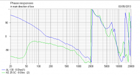
Conventional wisdom says metal domes don't go wrong till about 30kHz, but actually this phase plot for the Visaton KE25SC Ceramic dome paired with a metal woofer makes it clear that something is going worryingly wrong around 7kHz. I really don't know what to make of it.
The first bending mode of the dome, even an aluminum dome, is not what most people think. Most people say, "Here's our aluminum-dome tweeter, the first bending mode is at 23kHz." Not so. That's the second bending mode. The first bending mode is maybe at 200Hz. It's the second bending mode that's bothering them, which perhaps is at 23kHz. This is usually an oilcan mode, when the middle of the dome is going backwards while the outer edges of the dome are going forwards. It's not a rocking mode, which is not so much due to the dome—and whatever you make the dome out of—but is due to a suspension problem.
The first bending mode is when the outer edges just slightly begin to tip up. This is widely known. Don Barlowe, who is seriously underrated by I think almost everybody (footnote 2), has already written a number of papers about this. He described, in a paper on dome radiators he gave to the 50th AES Convention in London, the first bending mode as being low down.
Atkinson: You say that you think a cone tweeter might be a better way of going about it?
Marshall: Yes I do. Because when a dome goes into breakup, it's utterly, totally finished. Uncontrollable. That's it. There's nothing more to be had. When a cone goes into breakup, all that's happening, providing you can control it, is that the radiating area is diminishing. It's much easier to control that. There's a lot of work to do, of course. I wouldn't like to say that you can just take a sheet of paper and design a cone tweeter which is going to be a world-beater. But I'm sure there's a lot of scope. I shouldn't say this, should I? I should just go out and do it.
Atkinson: But can't you add damping to control the dome breakup, or use a material which has high intrinsic damping?
Marshall: Yes, but the damping makes things worse. You look at a soft-dome's frequency response—and that's how most people judge a tweeter—and if it's nice and flat, it's wonderful, isn't it? What it's not telling you is that the first worrying resonance, the second resonance, may be at 6kHz. It's heavily damped, it's very low-Q, but that means it's actually worse than if it's an aluminum dome. If you looked at it in the old-fashioned way of judging hi-fi in the 1970s and early 1980s, a low-Q resonance is great because you can't see it. But a low-Q resonance is far more worrying than a high-Q resonance.
Robin Marshall: A Modicum of Genius Page 4 | Stereophile.com
Conventional wisdom says metal domes don't go wrong till about 30kHz, but actually this phase plot for the Visaton KE25SC Ceramic dome paired with a metal woofer makes it clear that something is going worryingly wrong around 7kHz. I really don't know what to make of it.
Attachments
I regularly measure polar patterns and I have software that can reconstruct the mouth waveform from these patterns. Below 10 kHz I do not see any effects that could be called "chaotic" happening in any drivers that I have tested. Even above 10 kHz things are fairly well behaved.
I am with Art here - once EQ'd all compression drivers are close enough to each other, both measured and audible, that the differences are not worth worrying about (not unless one gets fixated on insignificant problems, which seems to be a common aspect of most audiophile discussions.)
Further, in a blind test of compression drivers with enough responders to be statistically significant there was no audible nonlinear effect - nonlinear distortion in a compression driver is not audible. This was published in the AES some years ago. There was small correlation to frequency response, but once this was corrected via EQ even this effect went away.
I came here just to correct a mis-statement attributed to me. I've done that and now I will go away as this thread is not really in the realm of discussions that I find attractive. Too much "I hear this" for me.
And hearing is not good. Not good at all.Too much "I hear this" for me.

And hearing is not good. Not good at all.
A few curious questions about the gedlee company AES test of the audibility of distortion in compression drivers.
1) How many listening test subjects? Who were they and what was their listening training? Are the results averaged?
2) The test shows a 1 in 5 correlation - p=0.203 that is significant the opposite the gedlee people claim
3) What was the input level of the drivers used during the test? I seem to remember it was 100 watts or 28 volts of drive. This is pretty much insane levels- most hifi home listeners drive their compression drivers with a few watts not 14, 20 or 28 volts
Why wasn't the comparison done with realistic input levels that would have "lower distortion" when in fact that is what gedlee are testing for?4) 15 seconds of "Burning Down the House" was the sole material used to get the "results" - hardly what I feel to be the most revealing piece of music
27 to 45 repeats (15 to 27 minutes!) of this is not natural and would make me run for the door - how many times did this cut have to pass through the sound card before the listeners heard it? at least 3 times5) Why was a 5000 watt subwoofer amplifier used to drive compression drivers that only require a few good watts?
This is an excellent point Lynn, and something I've discovered empirically.I hate to disagree with Dr. Geddes, but the kind of resonances we see in the Materion papers are beyond the scope of equalization.
[...]
Materion is right to draw attention to the decay times of the three different metals. In principle, a high-Q first mode can be equalized, but my experience with high-Q resonances from rigid diaphragms is that the resonance frequency is both very narrow and unfortunately moves around with level, making equalization very difficult. In other words, if diaphragm #16482 has a peak at 7.75 kHz, diaphragm #16483 will have a peak at 7.86 kHz, and then both peaks will wander around in frequency. You can set a notch filter to 7.8 kHz and hope for the best, but that's about the best you can do.
Conventional wisdom is that a resonance that manifests on all axes (eg is truly a mechanical resonance and not a diffraction artifact on a particular axis) can be corrected by EQ, but there is something else that must be true for this to be possible in practice - the resonance must be stable and not excessively high in Q, both of which are often not the case with cone resonances.
There is definitely an upper practical limit of the Q of a driver resonance that can be successfully corrected with EQ. The higher the Q the more precise the notch filter alignment has to be to give an acceptable result, particularly the centre frequency, yet typically the higher Q a mechanical resonance is the more unstable it becomes. A point is quickly reached where the resonance becomes too narrow and unstable.
In the example you give the resonance might change with drive level, on softer cones like paper it can also change due to variations in temperature and in particularly humidity. On a wide range driver the flexing of the cone at lower frequencies can even change the damping and centre frequency of the high Q breakup resonances at high frequencies, thus those resonances are not even stable from one moment in time to another and are modulated by the lower frequencies. All of which makes it impossible to EQ resonances that are too high Q and too unstable.
If you get a notch filter perfect the ringing in the time domain is also eliminated because the notch filter rings 180 degrees out of phase with the peak caused by the mechanical resonance and decays at the same rate, summing to zero ringing for that whole time however centre frequency, Q, and amplitude all have to be perfect, and they have to stay out of phase until they have sufficiently decayed.
Getting the centre frequency wrong when notching a high Q resonance often sounds worse than doing nothing about it. If the centre frequency is wrong even by say 100Hz at 4Khz on a high Q resonance then the two sets of ringing will start out of phase and cancelling but drift in and out of phase at a 100Hz rate, causing a 4Khz "tail" that is AM modulated at 100Hz...this shows up in a CSD as a decay tail that drops quickly at first but "rebounds" up and down.
A 100Hz centre frequency error on a low Q 4Khz resonance wouldn't matter because the resonance has decayed sufficiently before the phase between the two has had time to drift far.
Not directly relevant to your compression driver scenario but with wide range paper cones I find that while you often can't EQ some of the resonances of the cone for exactly the reasons described above (multiple high Q unstable resonances) that a combination of mechanical damping and electrical EQ can work wonders.
I've used stick on foam strips in a specially developed symmetrical but staggered pattern only near the perimeter of the cone which can drastically reduce the Q of the the main troublesome cone resonances but without hurting high frequency extension. What are left are much lower Q resonances which can be successfully and completely EQ'ed. (On some drivers some of the resonances can be almost cancelled out completely even before applying EQ to mop up what is left)
Because the foam becomes the dominant damping factor at the cone edge small changes in the damping characteristics of the paper with eg humidity or cone flexure which previously caused a large shift in the high Q resonances make an almost insignificant difference to the now low Q resonances.
So you end up with very stable low Q resonances that can be EQ'ed instead of very high Q unstable resonances that can't be EQ'ed.
Yep, exactly what happens with a single resonance and a misaligned notch as well - and it doesn't sound good.What I've actually measured from rigid diaphragms is not a single-frequency first mode, but two or more modes that are only separated by 50 to 200 Hz; this is why you see a pulsing pattern in the decay characteristics of metallic diaphragms.
Yes... they're noise like in that they literally do sound like noise superimposed on the music but they are program modulated. I think all that the "chaotic" "noise like" breakup actually is is a large number of closely spaced very high Q resonances.Add in the chaotic breakup that appears above the first mode, and then you see noiselike decay characteristics. But it isn't noise; the first mode and the chaotic modes are program-modulated.
Each resonance is stimulated by the program material and rings for a very long time (and therefore seems to be decoupled from the transient nature of the music, smearing it) but because there are so many resonances spread across a range of frequencies it sounds like "noise" rather than having the definite pitch of a single discrete resonance.
This is a common sound on poorly designed full range drivers - a chaotic noise like breakup in the upper midrange which can't be EQ'ed even digitally as its too complex and chaotic. Only mechanical damping can help with this sort of problem and again I've had good success with the foam strips removing this "chaotic" noise like breakup before EQ is even applied. (One reason why is that an EQ notch only targets an individual resonance, damping can target several resonances at once depending on where it's located on the standing wave pattern that forms on the cone)
Definitely agree. It baffles me when I see some people advocate higher Q resonances as being less audible than lower Q ones because they occupy a lot less bandwidth.Soft materials like Mylar diaphragms and paper cones are much more forgiving. The Q's of the first-order modes are broader and more stable, so notch filters work just fine, correcting both time and frequency domains.
Whether that's true or not (I don't think it is, higher Q mechanical resonances always sound more audible to me) the important point is that low Q mechanical resonances can be EQ'ed and eliminated completely, high Q mechanical resonances can't!
Last edited:
Hi Guys
I have to say that while sounding like a wet blanket, my experience has been similar to Earls and Arts’s. If you take the time to side by side - A vs B two identical horns with two different drivers, they will all sound different……until you equalize them to have the same frequency response. At that point, they will sound much much more similar. Understand, I am not saying there is no difference, it’s just that until you match the responses and levels, you are not really hearing the difference between drivers, you are hearing the different responses they produce on that horn. Since there ARE NO flat power response compression drivers AND NO horns that are perfectly CD, starting with a “not flat response” on a horn is also a fact of life.
Also, things like radiator breakup are NOT just indicators of the radiator “quality” but it’s geometry as well. Also, one isn’t limited to the traditional Dome, annular radiators also work too, maybe better if you need to get up high without breakup.
It is right to be concerned about breakup modes in ANY radiator but more so for drivers where the breakup falls in the ears sweet spot. In other words, if one looks at an equal loudness curve, one can see that ones ears are much less sensitive to a 3 or 5th harmonic which falls above 10Khz than to ones where the break up is in the 2-4Khz range. This is why seemingly very high levels of harmonic distortion are barely audible IF the harmonics are very high in frequency. For example, how much louder does the 5th harmonic of 5Khz have to be, to be detectable even against a silent background, compared to the sweet spot?
Now, break up is bad generally and here is why;
Pretend you had a driver that had a very simple shape breakup just one big mound at it’s top end and for fun, lets say it’s a mount +10dB over the flat level and centered at 2Khz.
So lets say you rolled that off with a 4th order crossover at 1Khz so that it is invisible in the final response, all fixed right?. While the amplitude response is fixed, the wart is covered by bondo.
So what you have is an acoustic system that has a big lump of gain (10dB) and it is after the voice coil. So now, pretend you’re driving the speaker at 400Hz way below the breakup and all is well right? Well not completely, the driver always has some harmonic distortion and what ever amount of 5th harmonic is has, that is still boosted 10dB by the breakup gain. Same for the 3rd harmonic at 660Hz and so on. A big lump of gain from breakup is not good.
Lynn, a lot of, maybe most PA speakers sound like crap, but you haven’t heard them all.
So many things are attributed to one thing but may be only correlation but not causality. For example, the very logical sounding but also incorrect concept that a large heavy woofer is “slow” because of the moving mass.
Also consider the task af a PA speaker, lets say its only 4 times farther from you than your home speaker. To produce the same loudness, it has to produce 16 times more acoustic power AND nearly every “bad thing” about loudspeakers gets worse much faster than the desired sound does.
Part two, the larger the room or space is, the more directivity and where the speaker is pointed governs how far away you can extract information like intelligibility of random words or preserve a stereo image. In large scale sound, directivity can make or break your understanding words or turns a live concert into a musical sounding roar.
The point is, given the cost is occasionally not even an issue when dealing with sound for 5,000-100,000 people, do you think large scale PA stinks because they simply choose not to do better?
No, the problem is the task requires too much acoustic power for one source and so they use many sources of sound and these are too far apart to combine coherently so they produce a complex interference pattern they argue “you can’t hear”. Well, we hear changes much faster than steady state issues so as soon as the wind blows or you move, you hear it. If you play pink noise and move around and hear swishy swishy, you are in an interference pattern. We use a signal which has one single time reference all the way to the loudspeaker but few consider preserving this is important for the loudspeaker and a long train of delayed and reflected snippets is what we hear.
A caution about Coax drivers in general, these are also appealing and logical sounding but very much compromised devices, VERY few have a “HF driver to cone as horn” transition that is anything close to ideal from a horn standpoint and the flat baffle edge termination makes a poor horn worse. About 8 years ago I had to design a couple ‘wide angle” products for work and sampled most of the likely Coax candidates and found only a few had a small enough perturbation to be acceptable. Also, a trend was the larger the Coax driver, the worse all that was. Eventually I went with an 8inch B&C which was the best at the time (and has a mylar hf diaphragm).
A better view of the spatial interference even a reputed “good” coax driver produces can be seen in the polar map of the Tannoy here;
3D3A Lab at Princeton University
Hi Pano
Multi-cells (the best) were an expensive comprise between acoustic loading at the low end for the driver and the desire / requirement to have as much as possible constant directivity especially up high where the traditional simple shapes greatly narrowed up high.
Between the pattern loss point and the point up high where the radius of curvature in the exit of each cell is too large compared to the wavelength, they can / did behave pretty well and like a section of a freely radiating single source would. Up high, they radiate as individual cells but they are at least very close together.
It was a combination of driver / amplifier technology, the ability to get by with less acoustic loading (a nail was “What’s so sacred about exponential horns”) and the MUCH larger cost to make one of more excellent multi-cells that lead to their end more than any problem with a well executed one in that day.
To this day, I love the way they look, I have a big 3X5 multi-cell on my roof as a yard ornament and occasionally bee’s nest.
Clearly, there are other ways to radiate as if one had a single source in time and space with a wider bandwidth than a single driver haha.
Best,
Tom Danley
I find that very hard to argue with, Tom. Until the frequency response is the same, we all have a hard time hearing past it. The FR will dominate. It's only after the frequency response has been equalized that we are free to judge other merits and flaws. But isn't that what crossovers are for? Shouldn't the crossover be built to give a reasonably flat response thru the pass-band? There may be some skilled listeners who can hear other flaws over gross FR errors, but I know I can not. Once we get past the FR, don't other traits stand out?I have to say that while sounding like a wet blanket, my experience has been similar to Earls and Arts’s. If you take the time to side by side - A vs B two identical horns with two different drivers, they will all sound different……until you equalize them to have the same frequency response.
I don't know if the mechanical resonances of drivers can actually be nulled with notch filters, but a number of smart people here say they can. My question: Even if they can, should they be? Is it wise to do so?
Let me take an example that I hope is not too far off the mark.
I've worked with a number of Altec A7 boxes that had terrific buzzes and rattles at certain frequencies. Typically the bass horn flares will buzz loudly in what seems like narrow Q resonances typically from about 100Hz to 250Hz. Each panel might have 2 or more resonances.
Not surprising, because as built they are not braced or damped. Adding a stiff brace + a coat of tar and sand will completely eliminate the resonances. Is that the right approach? Doesn't it make more sense to take care of the resonances in the mechanical domain rather than electrical? Would this be all that different from the resonances of cone materials or the diaphragms of a compression diver?
Hi Pano
Boy, there isn’t a yes / no answer I don’t think.
In the simple case example I used, one has a mound of gain placed between the motor and the radiation. As such, it can be equalized to be flat and with that simple behavior, fixing the amplitude also fixes the phase (hey it’s minimum phase magic).
What is not fixed is that gain still magnifies the harmonics in that same mound which are invariably produced at sub multiple frequencies of that mound. That may or may not be a concern. I know for me, I never worried about anything I didn’t know about haha.
This would be the case with the thin walls in the A-7 flares as well. (what I recall was they put a couple dips and little peaks in the response) I glued a couple braces in them but that only kills #1 and #2, but a load of damping is broad band and better. I remember thinking I bet these were a lot less dead before the wood had decades to dry out.
The real problem is that a radiator can become chaotic when in breakup ( a cymbal might be an extreme example). At this point it is beyond help and normally happens past the first simple modes.
If one were tasked with building a passive filter that would completely swamp out a woofers impedance which results in a load that was near the drivers Rdc, one would find that was possible, you can eq the drivers impedance with a conjugate circuit!!!
Now change the driver level and hey it’s a little off, drive it harder it off more and so on.
The T&S parameter view does not reveal that loudspeaker parameters themselves are a level dependent and prior history map, the stress / strain response of materials is often level dependent and can be nonlinear.
I have heard an explanation for chaotic behavior, maybe if Earl is still following along he could explain what happens between the simple modal behavior and chaotic behavior.
I did attend an AES presentation once where they were demonstrating a flat panel speaker driven in a number of places and by design driven into very complex modal behavior. The ETC measurement he showed struck me and being curious and suspicious. I asked what was that tail in the ETC after the main energy. His reply was wonderful I thought, much like how saying “Tax loophole” is intended to sound like an accident or oversight instead of provisions deliberately added, he said “oh that’s uncorrelated soundAre there any other questions (looking elsewhere)???”
Ah, so that’s random noise generated by the process?? Well, if it were random, at least it wouldn't add much to the harmonic distortion, even if they did have a plastic foam beer cooler “sound”.
Best,
Tom
As it happens, Pano, I have come to think that seeking a flat frequency response at speaker crossover might be the biggest mistake people make in audio.
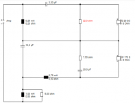
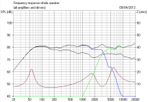
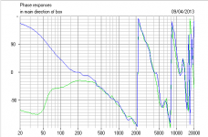
Quantum Theory says that ENERGY and TIME are related. But energy is not the same thing as frequency response when you try and integrate two drivers. Frequency response is momentum to me with my physics background, and that relates to position in quantum theory. We know that in a two way conventional speaker with flat frequency response, the overall energy takes a dip at crossover due to lobing above and below axis. I never get really good phase alignment with parallel Linkwitz-Riley filters unless I notch everything in sight. But the un-notched Butterworth series filter response with it's horrible +3dB peak (and actually FLAT POWER RESPONSE) works just great.
This time aligned series filter just seems to just WORK on a regular 6" bass plus 1" tweeter with no notches at all. BTW, time-aligned just means you set the tweeter back a couple of cms on the baffle, not hard.
Attachments
Last edited:
Well, I was afraid that my last posting would stir things up. That wasn't my intention; I'm still in the "mend/fix it mechanically or acoustically before resorting to electronics" school, and wanted to provide a little background.
It's part of the reason I don't completely trust simulations in loudspeakers or electronics: they're good first-order approximations, but they can also be completely wrong, too. Simulation, measuring (at high resolution), and listening are a good trio; when they don't match up, it's kind of annoying, but that also tells you there's a problem with one or more of the three.
It was reading Dr. Geddes' book (which I purchased at the RMAF show where he was exhibiting the Summa) that tipped me off that standard models of horns were nowhere close to what they actually did. That in turn led me to Bjorn Kolbrek and his BEM models, which were used to design the AH425 horn.
Buzzforb: The measurement software that was used on the first prototypes was not something I would have used myself (it was chosen by my collaborator), and I don't consider what I saw all that trustworthy. Nevertheless, it confirmed results obtained by Martin Seddon (Azurahorn) and Bjorn Kolbrek with their own AH425's, which matched Bjorn's BEM simulations.
Last edited:
Thanks Tom. I just doesn't make sense to me to fix things in the signal that could be fixed in the driver or the box. Well, it might be easier in the electrical domain these days with DSP, I just don't see how it's a better solution. Sometimes it may be the only practical or economical way to go, of course. Compromises, always.
NXT?I did attend an AES presentation once where they were demonstrating a flat panel speaker driven in a number of places and by design driven into very complex modal behavior.
Continuing reply to Buzzforb: Part of the reason for building my own set of LTO's is to do high-quality measurements of my own, using MLSSA (on an old 486 PC), and ARTA (with RME Babyface 192/24 USB 2.0 interface), with an 1/2" Aco Pacific instrumentation microphone.
The starting point crossover will the same as the first prototypes: 3rd-order Bessel with Zobel correction for the 15" bass driver, and 4th-order, transitional between LR and Bessel, for the AH425 & Radian 745 Neo, with autoformer/transformer attenuation between the driver and the highpass filter. Acoustical crossover around 700 Hz, with an option to go a bit higher.
Regarding the center speaker: Yes, I know coaxes have a lot of drawbacks. But ... a matching full-size LTO is out of the question. A 4" to 6" fullrange driver will not match the dynamics of the Ariel, much less the LTO.
So it has to be 2-way. It can be a compact vertical MT cabinet, with the same 5.5" driver as the Ariel (I bought some of the last stock at Madisound) and the Scan-Speak 93000, or a coax, as mentioned in previous posts.
It's not a high-priority project, since I already have the Dynaudio Contour CSX doing center-speaker duties, but a nice-to-have item so movies sound better. It will not be connected to the 2-channel all-triode system; the only amplifier it will see is the Marantz MM8003, which is an ordinary THX-certified Class AB transistor amplifier. When movies are playing, the LTO's will be switched over to the Marantz, so amplifier "voicing" between loudspeakers will not be an issue.
Last edited:
Hi Pano, Lynn, all
A problem is that sound in air exists in 3 dimensions, it has width, height and depth (X, Y and Z) and while DSP allows one to adjust Z (time / depth) it has no ability to fix errors in X and Y, that is a spatial problem. As a result if one is “fixing” sound from two or more acoustically separate sources with DSP, at best one can fix or align only one location in space. When people are concerned about aligning the lobe at crossover, it is because the sources are not normally combing into one new source, that causes them to radiate independently which produces an interference pattern and forms lobes (and the nulls which accompany it). These spatial things CANNOT be fixed globally electronically and can only be solved in the spatial domains that caused them.
System 7, once one has more than one source, has a crossover, then one has added another factor to the consideration. It was probably the late Richard Heyser’s “determination of loudspeaker arrival times” paper in 1971 that began the interest in loudspeakers time performance. It was his measurement system which was the first way to examine the loudspeaker in that way. In his view, the ideally, the loudspeaker appears to be a single wide band source occupying a single point in space and time. While that isn’t that hard on the scale of a headphone driver, even a single small full range driver is having problems because of the vast scale difference in the wavelengths being produced vs the radiators properties.
We are sensitive to a lot of things but I believe our hearing acuity is like our vision, we all respond slightly differently to things, it’s why I like deep purple but others like lime Green or Red. That is why (I think) there has been no “universal” solution, why there are Lowther fans, Fostex fans, cone and dome fans, coax fans, planar fans and horn fans. Each solution has distinct problems and limitations, each has a following who favors some aspects of each.
System7 suggests placing the tweeter behind the woofer is the direction and if you look at the phase response of the electrical crossover, one would conclude that is correct, the LF portion always emerges later than the HF portion from the filter.
The problem is, when you correct the GD of the filter by delaying or physically offsetting (and usually inverting) the hf driver, one finds that NONE of the text book filters deliver an acceptable response. Also, in a filter modeling program one is looking at the outputs of the filters but in the loudspeaker, one has drivers that already have their own magnitude and phase.
On the other hand, if at crossover, one can place the upper and lower range sources less than about ¼ wl apart AND one can derive the crossover shape which sums “flat” in mag and phase (no GD, not like a normal all pass sum), then one has what measures /acts / sounds like a single source.
I know this can be done, for the last 14 years I have been working on horn systems for large spaces which operate this way. The very first ones were called a Unity Horns and the modern evolution is the Synergy Horn (both patented). In a speaker like the SH-50), a 3 way system, there is no crossover phase shift or lobes and nulls at crossover and as it appears to be a single source, it can reproduce a square wave over more than a decade, spanning both crossovers.
Lynn, you are so right, a computer simulation is only as useful as it’s ability to predict what one measures in the real thing. A proper measurement ALWAYS trumps the computer model. For me, one cannot have faith in an acoustic model until one has measured what your modeling enough so that you figure out the minor unaccounted things that produce what one measures.. For example, in Akabak, for a bass horn or Tapped horn, a flexing panel looks like an unaccounted volume. Also, most acoustic models of horns and Tapped horns often over estimate the magnitude of the hf detail, showing high Q’s which cannot be realized a that scale and do not exist in measurements at all or at a lesser degree.
Until one backs up the model with measurements, it is anywhere from a reality to fantasy, pretty or not.
I don’t know what your budget is, but if your keen to know where the sound actually goes, Pat Browns company (ETC) can measure the loudspeaker every 5 degrees over an entire sphere for a few hundred dollars if you want.
That measurement (the data) is a requirement for us in commercial sound and WAY too hard for me or the shop to do.
Bottom line, a computer model is only as powerful as it’s prior proven ability to predict what one measures.
Pano, Oh, Why yes it was NXT. In the way old Intersonics / Servodrive days I knew a guy named Bertagni who made some flat panels that I thought sounded decent so when I heard about these new ones, I went to the paper. The Bertagni speakers had damping in them at the edges which made sense but “letting it rip” and the argument that “we can’t hear it” because (like now with the line array) the combing was so dense. That didn’t sound right (and the underwhelming success they had in spite of big marketing maybe suggests something).
If I put a single impulse into the speaker, THAT is what I want to get at the LP, just one copy, not stretched out in time, with harmonic structure intact and no rearanged by the loudspeaker.
The great difficulty involved is NO reason not to think of a loudspeakers ideal function is as a faithful part of the signal chain just like an amplifier or pre-amp and like any part of the chain, a Generation loss recording can produce a progressive caricature of what is wrong, what isn’t faithful to the signal.
Best,
Tom
I think Lynn pointed out a very important aspect, dynamics. However, there are many issues related with perception of dynamics. Then there is also a factor of what SPL level do we expect at a specific listening distance. These are so complicated that normally there is no fine line how you trade off in designs. Some aspects even relate with room characteristics. If we try to sort things out I would consider a short list below.
1. How high SPL would you design for at what distance?
2. Under 1, how fast can the CSD decay below audible levels?
3. How fast can the SPL rise to maximum in a coherent manner across the spectrum?
4. How much lower than the prime signal are the harmonics?
1. How high SPL would you design for at what distance?
2. Under 1, how fast can the CSD decay below audible levels?
3. How fast can the SPL rise to maximum in a coherent manner across the spectrum?
4. How much lower than the prime signal are the harmonics?
- Home
- Loudspeakers
- Multi-Way
- Beyond the Ariel