IslandPink said:Lynn
Which was the thread you had in mind, with GM and Planet 10?
MJ
Here's the Onken thread I was reading a few days ago. I don't think the alignment itself is anything that amazing, but I like the double-walled cabinet, particularly if the front edges have 45 degree slopes on the left and right edges, as Planet 10 has done with his variants.
As for the actual alignments, I favor resistive venting (which is a de facto 3rd-order highpass) or Bessel/Gaussian tuning for a more conventional 4th-order vented box. Oddly enough, when you look up a 6th-order Butterworth alignment with 6 dB of active equalization, if the equalizer is omitted, you get something very close to a 4th-order Bessel/Gaussian highpass alignment.
I like these alignments because they not only have good step response with minimum overshoot, but they are relatively insensitive to driver parameter variations under dynamic conditions. Other vented alignments can be rather touchy about parameter variations - I avoid those.
One offbeat variant might be with two paralleled 16-ohm 414's - the upper one in a closed box, and the lower one in a vented box. When working with multiple drivers in a common enclosure, I prefer to keep them separated, otherwise you get really weird-sounding crosstalk effects from driver to driver. If they're separated - well - there's no real reason to have the same exact alignment, in fact, they'll sound a bit better if the tuning is offset a bit.
As for myself, I'm going ahead with the more complex open-baffle approach, but the real voicing of the system will be the 800~900 Hz 414/288 crossover, and any associated equalization of the AH-425. Most horns, including these, will need some degree of slope equalization, and that can only be determined by gated MLS measurement at 2 and 3 meters distance.
414 data
Thanks Lynn
I don't know if the info has already been given but Steve Upchurch kindly provided me with T/S data for the GPA 414-8C (ceramic), and assured me the 414-8B (alnico) will be very similar :
RE 5.80 Ohm (23◦ C)
FS 26.6 Hz
QTS 0.21
QMS 5.84
QES 0.21
SD 81.71 in.2 (0.053 m2)
XMAX 0.15 in. (4 mm)
VD 12.26 in.3 (0.2 l)
VAS 10.49 ft.3 (297.0 l)
no 2.52 %
Sorry the greek characters got a bit mangled in transit , I had to compromise !
MJ
On the other hand the original Altec 414 8B and 8C weren't that similar :
http://www.rdrop.com/~billmc/speakers
and the old 8B certainly looks more logical in an Onken box , according to the spreadsheet I found ( from Lars ) .
MJ
http://www.rdrop.com/~billmc/speakers
and the old 8B certainly looks more logical in an Onken box , according to the spreadsheet I found ( from Lars ) .
MJ
")
Commercializing some ideas about OB & amps
Looks a bit like some of Mag's (the horn) & Lynn's (mid & woofer) work. Combined with the amp described the designer is familiar with Lynn's thinking on amps and speakers:
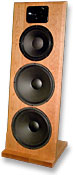
"K&Q Sound Genesis will be at the CES 2009 with their Model 1 loudspeaker and Model 2 tube amplifier. Led by founder Quoc, K&Q Sound Genesis produces unique speakers and tube-based amplifiers to audiophile standards. The Model 1 is a delicate sounding, high efficiency three-way loudspeaker with furniture quality, solid cherry wood open baffle. A 12-inch state-of-the-art paper cone and feed-forward midbass driver are mated with a highly efficient tweeter. There are no crossover points in the critical mid-range, allowing coherence of the driver to shine through. Two 15-inch paper cone woofers handle the lowermost registers while the treble range is produced by a smooth one-inch horn loaded compression tweeter. K&Q Sound Genesis Model 2 is a zero feedback, all transformer coupled, all direct heated triode, single-ended design using a 300B to drive another 300B. It is based on the seminal acoustic research findings and technology developments introduced by Western Electric in the late 1920s. This amplifier topology is rarely found in today's commercial tube amplifiers."
http://enjoythemusic.com/ces2009/preshow/e.htm
Would like to hear the amp/speaker.
Looks a bit like some of Mag's (the horn) & Lynn's (mid & woofer) work. Combined with the amp described the designer is familiar with Lynn's thinking on amps and speakers:
"K&Q Sound Genesis will be at the CES 2009 with their Model 1 loudspeaker and Model 2 tube amplifier. Led by founder Quoc, K&Q Sound Genesis produces unique speakers and tube-based amplifiers to audiophile standards. The Model 1 is a delicate sounding, high efficiency three-way loudspeaker with furniture quality, solid cherry wood open baffle. A 12-inch state-of-the-art paper cone and feed-forward midbass driver are mated with a highly efficient tweeter. There are no crossover points in the critical mid-range, allowing coherence of the driver to shine through. Two 15-inch paper cone woofers handle the lowermost registers while the treble range is produced by a smooth one-inch horn loaded compression tweeter. K&Q Sound Genesis Model 2 is a zero feedback, all transformer coupled, all direct heated triode, single-ended design using a 300B to drive another 300B. It is based on the seminal acoustic research findings and technology developments introduced by Western Electric in the late 1920s. This amplifier topology is rarely found in today's commercial tube amplifiers."
http://enjoythemusic.com/ces2009/preshow/e.htm
Would like to hear the amp/speaker.
Feed-forward midbass driver? What's that? It's an exotic amplifier design technique (that is fairly sensitive to reactive loads), but I've never heard of it described in the context of a loudspeaker before.
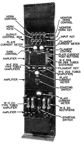
The WE quote is a bit odd as well. WE never made an all-trans-coupled SE amplifier for theater use; the single-ended 91A is cap-coupled (with a pentode front end), and the 86B and 92A amplifiers have PP output stages. The late-twenties 43A is PP as well, as you can see from the schematic. Note the use of a pair of 211's as HV rectifiers - this amp slightly precedes the invention of dedicated rectifier tubes. The filament pre-warmer switch (and separate filament and plate transformers) is a nice transmitter-style refinement that extends reliability.
Western Electric rack-mount as used in the late Twenties for the first-generation sound-on-disc movies. (The 86B, 92A, and 91A were introduced in the Thirties and were contemporary with 35mm optical-sound movies and the introduction of the MGM Shearer Sound theatre speaker.) A single 86B, 92A, or 91A amplifier would replace everything in this entire rack, since they incorporated photo-detector pre-amplifiers.
Re: Commercializing some ideas about OB & amps
So according to the designer, the drivers appears to be dual Selenium 15PW3-SLF for the lows, an 18Sound 12NDA520 running full range, and a B&C DE250 compression driver for the highs. The horn looks like something from an 18Sound XD125.
Enjoy the Music[/i] [B]K&Q Sound Genesis Model 2 is a zero feedback said:FWIW, there's a thread on this design over at AudioCircle here. The designer Quoc makes a brief appearance.
So according to the designer, the drivers appears to be dual Selenium 15PW3-SLF for the lows, an 18Sound 12NDA520 running full range, and a B&C DE250 compression driver for the highs. The horn looks like something from an 18Sound XD125.
Thanks for the link to the AudioCircle thread, where it looks like thoughtful choices were made by Quoc about the driver line-up. The PR material about the "feedforward midbass driver" was probably garbled by the marketing flacks, inaccurate transcription from the show reporter, or both.
Regarding my own plans over the next several months, here's what's on the agenda:
1A) MLS measurements at 2-meter distance at 0, 5, 10, 15, 30, and 45 degrees off-axis with the AH425 and GPA 288/Alnico. I will be looking at which angle gives the fastest settling time in the time domain, and see how much equalization that requires in the frequency domain. Time-domain errors are frequently not correctable by equalization, which is why it is important to determine which emission angle is most favorable. I will be on the lookout for narrow spikes in directionality, which indicate problems with reflections and diffraction.
1B) The decision to keep or discard the AH425 + 288 will be determined by the time-domain measurements. A lot of clutter in the time domain indicates trouble with the horn and/or the diaphragm - I expect to fool around with damping materials and see what effect they have on time-domain performance.
2) If the AH425 + 288 are retained (which I expect), then equalize as necessary and make a first rough cut at the highpass crossover (2nd-order or higher order acoustic highpass function).
3) Quick complementary lowpass function for the OB GPA 414, and another quick attempt with the 12NDA520, so they can be compared. This gives a basic, semi-listenable 2-way system.
4) If the AH425 + 288 fall short, the next option is to try a plastic-film 1" compression driver like the B&C DE250 with an adapter plate for the AH425.
5) The next fallback plan is to discard horns and compression drivers, utilize the paired RAAL tweeters down to 2 kHz, and see how well the GPA 414 or 12NDA520 work up to 2 kHz. This is not a very attractive option, since it "stretches" both sets of drivers to the limits of their performance envelope. Stacked 18Sound midranges will also be assessed, but I do not have high hopes for these.
6) Once the critical mid-high region is sorted out (which determines the basic character of the speaker), then move on to either a single or paired 15" drivers for the bass-fill section (250~300 Hz lowpass filter).
7) Subjective fine-tuning follows all of the above steps - I don't even want to listen to a speaker unless I know the basic characteristics (rapid settling time and reasonably flat response for first-arrival sound) are doing what they should be doing.
The problem with subjective twiddling with an uncharacterized speaker is that you're never really sure what it SHOULD sound like, so you just end up re-EQ'ing for each recording. No thanks. The numbers have to be there first, then all the fancy stuff follows.
If there are gross problems in the time domain, as mentioned earlier, these can be very hard to correct with equalization, since time problems are typically non-minimum-phase and are created by internal reflections and diffraction. And subjective "EQ" can be even worse, since the appropriate settings will depend on the transient content of the music being played. Much better to keep time-domain clutter to the minimum, and aim for the quickest settling time possible. This also simplifies the equalization picture as well, since systems with rapid settling times are usually flatter and have fewer problems with hard-to-equalize narrowband notches and peaks.
8) I give much more weight to first-arrival sound than most other contemporary designers, to forestall the inevitable questions about directivity. If there's clutter in the 1~5 mSec time interval, I don't care about the directivity - I work on the clutter first, and let the directivity fall where it may. Since time clutter is traditionally problematic for horns, this should be an interesting exercise.
Lynn Olson said:
4) If the AH425 + 288 fall short, the next option is to try a plastic-film 1" compression driver like the B&C DE250 with an adapter plate for the AH425.
5) The next fallback plan is to discard horns and compression drivers,
Your assuming that the horn can't be the problem. Why is that? In my experince that will be the most likely failure.
John Sheerin said:Having been doing some FEA on Le Cleac'h horns the last few days, I can say there will definitely be diffraction from the mouth of the horn due to the incomplete roll back.
All horns and waveguide have some diffraction at the mouth, it has to happen. The key is how to minimize this. It is easy to show that an enclosure helps, i.e. put the device is as large an enclosure baffle as possible. The idea of having the horn free standing is a very bad one IMO. As large a radius flare at the mouth as possible in as large a baffle/enclosure as possible - thats the best you can do, but this works fairly well.
Hello John,
I agree that a complete rolled mouth lead to lesser diffraction amount for the Le Cleach horn. I allways recommanded to reach at least an opening angle of 270° minimum and 360° if possible for the radial tangential to the mouth.
In the passed months, many long duration BEM simulations have been done in order to compare Le Cleach horns to OS waveguides (even with a curved mouth) and, when it comes to mouth diffraction, the Le Cleach horn (even the AH425) have, by far, less diffraction than an OS waveguide and the pressure field inside the horn is more evenly distributed than in the OS waveguide.
Best regards from Paris, France
Jean-Michel Le Cléac'h
John Sheerin said:Having been doing some FEA on Le Cleac'h horns the last few days, I can say there will definitely be diffraction from the mouth of the horn due to the incomplete roll back.
Well, that's why I'll have to measure, rather than rely on theory or simulations. Impulse response, particularly over a wide range of emission angles, seems to be the most neglected area of horn research.
Even if there is a "failure" leading to abandonment of the AH425, other horns, or OS waveguides, I'll be measuring them in the time, frequency, and CSD domains as I go. If I end up using conventional direct-radiators, at least I'll have a set of measurements on how different horns and waveguides behaved. Anything that yields more hard data is a plus, in my view - that justifies the investment in time and money right there. As I become more physically fit (thanks to working out 3 times weekly at the local gym), I'll be able to make the measurements and get started. You'll see them here first.
When I started the Ariel 15 years ago, there was not much published on the impact of cabinet edge diffraction on time response, and the success or non-success of felt or foam linings to minimize it. Long story short, felt and foams didn't work all that well, contrary to expectations. The only effective measure was a combination of off-center tweeter mounting combined with large-radius cabinet edges. This is all considered obvious now, but it wasn't that obvious in 1993.
The reason I was curious about edge diffraction was an experimental Audionics speaker I built in 1978 that looked like a giant vitamin capsule, with large radii everywhere. My measurement equipment back then was a Tek scope and squarewave-generator setup, and the FR was done with the Altec 1/3 octave realtime analyzer. Although the square wave was difficult to interpret - much sweeping up and down in frequency was needed - it was clear the reduction in diffraction was worthwhile. (FFT systems in 1978 involved dedicated anechoic chambers, $100,000 rack-sized DEC minicomputers, and a staff programmer to write the Fortran measurement, computation, and display routines - all out of Audionics' reach financially. KEF in England was one of the very few companies doing this at the time.)
Aside from the difficulties in fabrication - this project drove the woodshop nuts - controlling the dominant top-to-bottom cylindrical mode in the cabinet was not at all easy. Many years later, B&W came up with the "Nautilus", a clever reverse-horn flare for damping the backwave from the driver.
Unlike many speaker designers, I'm not working from a larger meta-theory - I'm really just poking around, trying to see how these gizmos work. I've been led astray so many times by the prevailing theories in the audio biz I always like to do my own measurements, and see how these things physically work, as opposed to the theoretical model. It's the departure from theory that's always the most interesting. (That's a lesson I wish economists would learn.)
1978 was pretty early days for looking at diffraction - but that was was due to lack of good techniques for time-domain analysis as much as anything. Although KEF had their equivalent of the CSD back then (and mostly used for internal use), the Brits seem to like their square-sided cabinets with attractive veneer finishes.
One of the sad discoveries of the experimental Audionics speaker was the ideal exterior shape (an approximation of a sphere) was also the worst interior shape. Controlling that interior standing-wave mode was very difficult in a hemisphere-ended cylinder 18" high - and the coloration was really obnoxious. One of the subtle advantages of a conventional box with dissimilar HWD dimensions is a scrambling and partial randomization of the interior standing-wave modes. Try the same thing with a cubical or spherical enclosure and you'll find the remaining single high-Q mode is very, very difficult to control, no matter what magic damping materials you try.
I'm looking forward to seeing what MLSSA says about various horns and waveguides - for one thing, horn and waveguide theories typically omit the effects of the phase-plug, and assume perfect pistonic (or pulsating spherical) diaphragms at the entrance of the horn. So right there, a departure from theory can be expected, although I have no way to guess what this will be.
Quite true.
I have not seen many horn or wave guide users publish impulse response, or CSD data. Most SPL data seem smoothed. There is still much to be learned after all these years. I recall Earl showed some impulse response a long time ago. Most problems occur right around the throat to the diaphram.
I have not seen many horn or wave guide users publish impulse response, or CSD data. Most SPL data seem smoothed. There is still much to be learned after all these years. I recall Earl showed some impulse response a long time ago. Most problems occur right around the throat to the diaphram.
- Home
- Loudspeakers
- Multi-Way
- Beyond the Ariel