john k... said:
Yes with the result that excursion would be reduced by another 24dB or by a factor of 0.063 with a subsequent similar reduction in modulation index.
Sure
gedlee said:I didn't go through the analysis in detail, but while the net acoustic response below the -12 db/oct HP filter falls at -24 dB / oct, the excursion only falls at -12 dB /oct. I hope that you are considering this fact.
Maybe add kind of SOA to my spreadsheet.
john k... said:At a given frequency SPL goes like 20 Log (X) so if the SPL is reduced by 6 dB excursion halved.
For constant SPL vs frequency, excursion goes like 1/f^2, or for constant excursion, SPL increase at 12dB/octave.
The initial argument was that for a 2nd order acoustic response with corner frequency around 2k Hz a tweeter would have the same excursion at 100 Hz as at 2k (approximately) when driven by a signal of constant anplitude vs frequency. If the tweeter had an Fs of 500 Hz and was filtered by a 2nd order electrical filter the acoustic response below 500 Hz rolls off at 24dB/octave and would be down another 24dB, more or less (two octaves), at 100 Hz compared to the 2nd order acoustic roll off (all the way to DC). The additional 24dB reduction in SPL at 100 Hz would reduct the excursion by a factor of 0.063 from that which it would be if the acoustic roll off remained 2nd order below Fs.
Thanks – it's good to have it in clear figures.
Lynn Olson said:
the interesting investigation - the apparent translation from FM to AM modulation artifacts is most interesting. It underlines why multiway systems, for all of the faults, have greater dynamic range, thanks to significant decreases in nonlinear distortion artifacts. The effective acoustical slopes of the crossover have major effects on the "area under the curve" when the excursion of the driver before and after the crossover is compared - and this "area under the curve" is the source of the artifacts we see above.
The artifacts are real and exist in the physical world; audibility, of course, is another matter.
For the math genius' and the ones dealing with that all day its trivial.
But for the rest of us ...
Though I'm fairly familiar with the topic I always have to check back.
Knowing – as also clearly outlined by others – its hardly ever happening that we will have 100% modulation index – it nevertheless might complete the picture in how side band artefacts develop with increasing / decreasing Doppler intermodulation.
Going back to what I have posted at the very beginning, it is interesting to note that even the "pure" amplitude modulated signal (RED trace) develops a bunch of side bands.

Referring to the time domain plot:
"Pure amplitude modulation" (RED trace) here is meant as the sine wave peak points are equally spaced from each other.
The BROWN trace is "pure" frequency modulated meaning the peak points are *not* equally spaced from each other *but* the amplitude remains constant.
Not sure my semantics confirm with any standards in this regard.
")
Anyway - looking at the frequency domain plots - we notice a almost similar spread out of side bands for what looked completely different at the time domain plot.
Main difference is that the fundamental and the even order side bands are attenuated if we *not* only take the front radiated SPL into account.
In my last posting I already mentioned as a side note that there are similarities of the sound pattern for Doppler modulation and for clock jitter (– at least from what plots can tell us).
( Might be that triggered my special interest even more.
)Basically clock jitter in digital audio devices shifts the frequency according to that jitter – very much the same as does Doppler intermodulation.
To put into perspective what *I* found to be audible in this regard lets have a look at the measurement below

The zoomed plot shows a jitter measurement of my pro-soundcard.
It already performs very well regarding to clock jitter but any improvements still resulted in audible better performance.
Note that its rather a "smeared" spread out of "sidebands" (appearing in shape of a smooth hill rather than in single steep peaks) as is typically for noise generated random jitter – something quite similar to what I would expect for speakers with back chamber walls *not* equally spaced to the membrane.
Someone should do some math's to calculate what this –110dB translates into - in terms of audible intermodulation distortion threshold.
Michael
mige0 said:Someone should do some math's to calculate what this –110dB translates into - in terms of audible intermodulation distortion threshold.
Some time ago I looked at jitter in terms of its audibility and here is what I concluded. Random jitter is not a problem at all because it can be shown to be identical in effect to "dither" noise added to the signal which is know to actually improve the audibility. However any discrete components in the jitter - such as yours shows - admittedly at a low level - will be high audible.
So just like nonlinear distortion, its NOT the absolute level of the jitter (or THD) that is audibly important but the spectrum and details of these effects. In both cases the ear is quite tollerant of some forms but quite intollerant of others. Basically random effects tend to be inaudible to actually pleasing to the ear while coherent effects interfere with the siganl and the ear doesn't like this. Of course nonlinear distortion can be coherent and/or incoherent so things are never really that simple.
EnABL and ESL?
Sorry for me interrupting the thread, but it seems to be the only place where surface treatment is seriously considered and known.
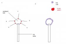
In the attachment, a pic with two variants of applying treating to an ESL is provided. On the left, it's cardboard tube along the edge of panel, with felt near the panel and several EnABL patterns along it's circumference. I'd also like to know if really several patterns are needed.
On the right, the whole tube is just coated with felt.
The question is, which is more beneficial?
Also, would adding felt between stator and diaphragm along the edge of panel help as well?
Edit: forgot the attachment..
Sorry for me interrupting the thread, but it seems to be the only place where surface treatment is seriously considered and known.
In the attachment, a pic with two variants of applying treating to an ESL is provided. On the left, it's cardboard tube along the edge of panel, with felt near the panel and several EnABL patterns along it's circumference. I'd also like to know if really several patterns are needed.
On the right, the whole tube is just coated with felt.
The question is, which is more beneficial?
Also, would adding felt between stator and diaphragm along the edge of panel help as well?
Edit: forgot the attachment..
Attachments
gedlee said:
Some time ago I looked at jitter in terms of its audibility and here is what I concluded. Random jitter is not a problem at all because it can be shown to be identical in effect to "dither" noise added to the signal which is know to actually improve the audibility. However any discrete components in the jitter - such as yours shows - admittedly at a low level - will be high audible.
So just like nonlinear distortion, its NOT the absolute level of the jitter (or THD) that is audibly important but the spectrum and details of these effects. In both cases the ear is quite tollerant of some forms but quite intollerant of others. Basically random effects tend to be inaudible to actually pleasing to the ear while coherent effects interfere with the siganl and the ear doesn't like this. Of course nonlinear distortion can be coherent and/or incoherent so things are never really that simple.
Can you give a definition for coherent and incoherent nonlinear distortion? If I'm understanding you correctly, coherent would be 'traditional', or H2, H3, and soforth, and incoherent would behave.....how?
thanks
A quick writting may have caused me to use the wrong words, but here is my point.
Odd harmonics from a nonlinear process (with a pure sine wave input) will be correlated with the input signal and cross correlation will not remove their effects. On the other hand even orders are not correlated with the input signal so cross correlation will remove their effects. In terms of coherence then the odd would be coherent, but the even would not.
This is easily seen as follows. The odd harmonics affect the amplitude of the input signal, but the even don't. So even if we cross correlate the pure sine wave input with the output the effects of the odd order nonlinearities will be present in the result - i.e. the main signals amplitude will be affected. Even orders don't affect the amplitude and as such their effect will not be seen after we do a cross correlation.
I'm not implying anything regarding audibility here, just the pure mathematical relationships involved.
gedlee said:
Some time ago I looked at jitter in terms of its audibility and here is what I concluded. Random jitter is not a problem at all because it can be shown to be identical in effect to "dither" noise added to the signal which is know to actually improve the audibility. However any discrete components in the jitter - such as yours shows - admittedly at a low level - will be high audible.
So just like nonlinear distortion, its NOT the absolute level of the jitter (or THD) that is audibly important but the spectrum and details of these effects. In both cases the ear is quite tollerant of some forms but quite intollerant of others. Basically random effects tend to be inaudible to actually pleasing to the ear while coherent effects interfere with the siganl and the ear doesn't like this. Of course nonlinear distortion can be coherent and/or incoherent so things are never really that simple.
Love to see you speculating - spreading out into details not being carved in stone yet, Earl
Not being specialised on the topic of dither I would put it different though.
Basically dither was "invented" (or at least came into an everybody's mind) to mask the imperfections that became apparent with 16bit coding .
Meaning nothing else than 16 bit coding isn't sufficient for our hearing ability - and second - that one bad system has been masked with overlaying an other bad system .
If I remember correct dither is done somewhere in the last significant bit or so only.
I'm with you to the point as there *is* a difference about distortions whatsoever be it correlated to the signal versus un-correlated (random - like noise, in other words).
Where your conclusions go wrong IMO is when you perceive the jitter shown in the last posting of mine as to be correlated.
To give an other example:
An externally hosted image should be here but it was not working when we last tested it.
*This* *is* a highly correlated jitter (or in this case - one with stable modulation freqeuncies).
No smooth hill but only sharp single peaks.
Same as we saw it in my simus for speaker back chamber reflections – and what I would expect to show up that way in measurements of speakers with rear chamber wall equally spaced to the membrane.
About the *conclusions* you come to regarding what *might* be heard or not – well, I already *have* heard.
Might be, I'm not representative for any majority but simply put – we are *not* insensitive to random effects – they are by no means "inaudible to actually pleasing to the ear" - *in gerenral*.
I already know you are a big fan of "randomising" as cure to imperfections (as in cases, it even might be the "no good" but the "best available" option) but basically you always smear what should be reproduce accurate – or to see it from another perspective – put another veil instead of unveil details actually available.
Michael
Lovely take on even and odd order harmonics I have to run a simu to visualise that for me
Well you misunderstand "randomizing" in my context and your explaination of "dither" is incorrect.
Dither does not mask the errors in the LSB, it randomizes them to be incoherent with the waveform and as such allows signals to be used down to the LSB without audible distortion. Dither is completely different than masking. All digital channels use this technique including video. And my idea about randomizing is not to "mask" the signal with noise ("a veil"), but to randomize the coherent errors in such a way that they are not as audible - exactly like dither.
Dither does not mask the errors in the LSB, it randomizes them to be incoherent with the waveform and as such allows signals to be used down to the LSB without audible distortion. Dither is completely different than masking. All digital channels use this technique including video. And my idea about randomizing is not to "mask" the signal with noise ("a veil"), but to randomize the coherent errors in such a way that they are not as audible - exactly like dither.
gedlee said:Well you misunderstand "randomizing" in my context and your explaination of "dither" is incorrect.
Dither does not mask the errors in the LSB, it randomizes them to be incoherent with the waveform and as such allows signals to be used down to the LSB without audible distortion. Dither is completely different than masking. All digital channels use this technique including video. And my idea about randomizing is not to "mask" the signal with noise ("a veil"), but to randomize the coherent errors in such a way that they are not as audible - exactly like dither.
You wouldn't agree that my take about dither "in layman's language" is *exactly* what you say "in scientific language" ?
Wouldn't you agree that the "positive" effect of dithering you mention would be inaudible with audio coding way higher than what we have now ?
- Meaning we would need *no* dither at high resolution to get same distortion perception as we now have with dither and low resolution .
Michael
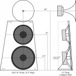
I am in negotiation with AESpeakers for an open-baffle variant of the TD15M; I'll be buying four of these for the two bass modules. More to follow, including specifications.
Thoughts about the 2008 RMAF
Thoughts about the 2008 RMAF
Hello Mr. Olson,
After having the RMAF experience with the RAAL omni midrange, would you use an array of 4 smaller midranges (4"-6") in order to gain some advantages (as sensitivity) over a single 15" or 12" driver?
Or the integration problems are too hard to worth the effort?
After having the RMAF experience with the RAAL omni midrange, would you use an array of 4 smaller midranges (4"-6") in order to gain some advantages (as sensitivity) over a single 15" or 12" driver?
Or the integration problems are too hard to worth the effort?
Just ordered four TD15-Dipoles from AESpeakers, and I expect John Atwood will order two more. (The name is made up; I don't know what John J will actually call them.) Pricing is similar to the existing TD15M and Dipole15 drivers.
The drivers are essentially TD15M cones, spiders, and cloth accordion surrounds, with Dipole15 voice coils and magnet structures. What I wanted was a reasonably efficient woofer similar in character to an Altec 515/416, with a high-quality cone, spider, damped cloth accordion surround, and underhung voice coil, combined a Qts and Fs suitable for open-baffle or IB use.
The T/S specifications of the new driver are:
Fs: 33.8Hz
Qms: 19.4
Qes 0.86
Qts 0.82
Vas 311 Liters
Cms 0.3 mm/N
Mms 74 grams
Sd 855 cm2
Rms .81 Kg/S
Bl: 7.5 T/m
Re: 3.1ohms
Z 4 ohms
Le 0.0375 mH
Pe (max) 100 Watts
Pe (transient) 250 Watts
1WSpl: 93.5 dB
2.83V: 97.6dB
Linear Xmax 9 mm (peak)
Mech Xsus 12 mm (peak)
By contrast, the T/S specifications of the Dipole15 (with foam surround) are:
Fs: 21.66Hz
Qms: 15.16
Qes: 1.002
Qts: 0.94
Vas: 623L
Mms: 90g
Xmax: 13mm peak
Voice coil height: 12.4mm
Air gap: 38.4mm
Sd: 855cm2
Re: 12.3 ohms
Le: 0.3mH
Z: 16 ohms
Bl: 12.26Tm
1W SPL: 90dB
Pmax: ~100W
Quite different - more oriented towards deep-bass use, with a foam surround, more Xmax, and a lower Fs.
The TD15M (8 ohm, cloth accordion surround) specifications are:
Fs: 34.7Hz
Qms: 5.09
Qes: .35
Qts: .33
Vas: 312L
Cms: .3mm/N
Mms: 70g
Rms: 3kg/s
Xmax: 6mm
Sd: 855
Re: 6.6
Le: .2mH
Z: 8 ohms
Bl: 17Tm
1W SPL: 97.8dB
2.83V SPL: 98.6dB
no: 3.61%
Pmax: ~500W
As you can see, the new drivers are midway between the TD15M and the Dipole15's, and feature the advanced technology of the Lambda series: underhung voice coil, extended pole piece & heat sink, magnetically shielded gap structure, very low inductance, and a flat and stable BL product (and inductance) as the voice coil moves back and forth.
These drivers should complement existing widerange woofers and midbass drivers, and offer higher quality in the midbass region than the high-Q guitar speakers that are typically used for open-baffle bass-augmentation applications. Unlike a guitar speaker with the characteristic limited Xmax and a sharp 5~10 dB peak in the 2~5 kHz region, the new drivers have 9mm peak (18mm total) Xmax, and flat response in the 1~5 kHz region, which relaxes filtering requirements substantially.
Lynn Olson said:Just ordered four TD15-Dipoles from AESpeakers,
Hi Lynn,
Are you still working with AES on the 18" dipole woofers you described in your slant 15 design? The extra area, larger Xmax, and lower Fs would seem best suited for dipole bass, and it would be interesting to see what AES could come up.
I have been using Lambda Dipole 15 and appreciate the low Fs and decent Xmax, but think the Qts=0.94 is too high and sacrifices some cone control. I'll be interested in your review of the new Qts=0.82 TD15M Dipoles.
Do you plan to review any AES midranges as a dipole alternative to your monopole midrange horn? I think AES is planning 6.5", 8" and 10" wide bandwidth midrange speakers to fill out their product family.
Attachments
Back Diaphragm Mirror Distortion
Running some more simulations– or thinking about it in some more depth – rather than speculating, I could have known better
The simu below is done in averaging three back membrane mirrors sources at a distance of 0,3mm / 10mm / 27mm
Different arrival times of the mirrored sources due to *not* equally spaced back chamber walls from the speakers diaphragm, do *not* smear the side band peaks.
They simply stay in place.
What *is* different with multiple rear chamber reflections is, it becomes sort of indistinguishable - in time *and* frequency domain - from the behaviour of purely front membrane radiated D-IM - unless time of flight for the rear SPL comes into wavelength territory – which hardly is the case for usual mid / high compression drivers and magetostatic drivers as well.
If that Doppler generated "Back Diaphragm Mirror Distortion" could be verified clearly by measurement, it will have ( and explain ) some interesting and very practical impacts regarding speaker design / selection, crossover design and maybe could be even stretched to different sonic perception of enclosures ( closed, vented, OB, horns)
But rather than loosing myself in further speculations I'm doing some measurements
That JohnK wasn't able to get any useful results by his measurements did set a high hurdle.
So I decided to borrow a horn for the time waiting for the magnetostatic speaker to arrive and perform some quick first measurements.
Maybe its interesting for those who would like to verify my findings to outline the whole measurement procedure first.
As there doesn't exist any reliable data to calculate liner x-max of the ElectroVoice ST350 CD horn, I first checked out what voltage level corresponds to a –20dB (10%) third harmonic distortion on 100Hz.
A word of caution for those who want to give this procedure a try – keep the adjustment time to find the –20dB third harmonics *very* short – no more than 2-3 sec ! – as voice coil heat up starts immediately - clearly displayed (and audible) by rapid distortion raise. Don't burn the VC !
Then the level of the modulation frequency was set –20dB and –40dB below that and the two tone measurement was carried out
2kHz without modulation:
2kHz with 100Hz –20dB x-linear-max modulation:
2kHz with 100Hz –40dB x-linear-max modulation:
As can be seen there is a very good correlation to the behaviour predicted by the simulations. The effect of "Back Diaphragm Mirror Distortion" is clearly visible as attenuation of the even order side bands as outlined in posting #4650
http://www.diyaudio.com/forums/showthread.php?postid=1645445#post1645445
The " Back Diaphragm Mirror Distortion " topic seems to get interesting !
I hope that with my next measurements I am able to show the effect of "Back Diaphragm Mirror Distortion" directly compared to front radiated Doppler intermodulation distortion.
Must have to check first if the magnetostat allows operation with the back chamber wall opened and if the back pole piece is perforated as well.
Michael
PS:
For those who want to go further into the dither topic (not really related IMO) to make up his mind by a more detailed explanation :
in English
http://www.rme-audio.com/english/techinfo/dither.htm
in German
http://www.rme-audio.de/techinfo/dither.htm
Have read some time ago – should still be up to date ...
mige0 said:
An externally hosted image should be here but it was not working when we last tested it.
Note that its rather a "smeared" spread out of "sidebands" (appearing in shape of a smooth hill rather than in single steep peaks) as is typically for noise generated random jitter – something quite similar to what I would expect for speakers with back chamber walls *not* equally spaced to the membrane.
Running some more simulations– or thinking about it in some more depth – rather than speculating, I could have known better
The simu below is done in averaging three back membrane mirrors sources at a distance of 0,3mm / 10mm / 27mm
An externally hosted image should be here but it was not working when we last tested it.
Different arrival times of the mirrored sources due to *not* equally spaced back chamber walls from the speakers diaphragm, do *not* smear the side band peaks.
They simply stay in place.
What *is* different with multiple rear chamber reflections is, it becomes sort of indistinguishable - in time *and* frequency domain - from the behaviour of purely front membrane radiated D-IM - unless time of flight for the rear SPL comes into wavelength territory – which hardly is the case for usual mid / high compression drivers and magetostatic drivers as well.
If that Doppler generated "Back Diaphragm Mirror Distortion" could be verified clearly by measurement, it will have ( and explain ) some interesting and very practical impacts regarding speaker design / selection, crossover design and maybe could be even stretched to different sonic perception of enclosures ( closed, vented, OB, horns)
But rather than loosing myself in further speculations I'm doing some measurements
That JohnK wasn't able to get any useful results by his measurements did set a high hurdle.
So I decided to borrow a horn for the time waiting for the magnetostatic speaker to arrive and perform some quick first measurements.
Maybe its interesting for those who would like to verify my findings to outline the whole measurement procedure first.
As there doesn't exist any reliable data to calculate liner x-max of the ElectroVoice ST350 CD horn, I first checked out what voltage level corresponds to a –20dB (10%) third harmonic distortion on 100Hz.
An externally hosted image should be here but it was not working when we last tested it.
A word of caution for those who want to give this procedure a try – keep the adjustment time to find the –20dB third harmonics *very* short – no more than 2-3 sec ! – as voice coil heat up starts immediately - clearly displayed (and audible) by rapid distortion raise. Don't burn the VC !
Then the level of the modulation frequency was set –20dB and –40dB below that and the two tone measurement was carried out
2kHz without modulation:
An externally hosted image should be here but it was not working when we last tested it.
2kHz with 100Hz –20dB x-linear-max modulation:
An externally hosted image should be here but it was not working when we last tested it.
2kHz with 100Hz –40dB x-linear-max modulation:
An externally hosted image should be here but it was not working when we last tested it.
As can be seen there is a very good correlation to the behaviour predicted by the simulations. The effect of "Back Diaphragm Mirror Distortion" is clearly visible as attenuation of the even order side bands as outlined in posting #4650
http://www.diyaudio.com/forums/showthread.php?postid=1645445#post1645445
The " Back Diaphragm Mirror Distortion " topic seems to get interesting !
I hope that with my next measurements I am able to show the effect of "Back Diaphragm Mirror Distortion" directly compared to front radiated Doppler intermodulation distortion.
Must have to check first if the magnetostat allows operation with the back chamber wall opened and if the back pole piece is perforated as well.
Michael
PS:
For those who want to go further into the dither topic (not really related IMO) to make up his mind by a more detailed explanation :
in English
http://www.rme-audio.com/english/techinfo/dither.htm
in German
http://www.rme-audio.de/techinfo/dither.htm
Have read some time ago – should still be up to date ...
LineSource said:
Hi Lynn,
Are you still working with AES on the 18" dipole woofers you described in your slant 15 design? The extra area, larger Xmax, and lower Fs would seem best suited for dipole bass, and it would be interesting to see what AES could come up.
Although a 18" driver can have up to 1.5 times the emissive area of a 15" driver, the cones tend to be more suitable for subwoofer use, which is how they are used professionally, and choosing or developing a new cone is a non-trivial project. The more I thought about it, 18" drivers are at the outer limit of paper cone size (in terms of breakup control), and this is why they are quite a bit heavier than the area alone would indicate - in professional use, a floppy, breakup-prone 18" driver would be very undesirable, so the cones are quite heavy relative to their area. The heavy cone mass, along with very long voice coils and formers, has an impact on the midrange response.
By contrast, 15" paper-cone woofers are a well-known technology in continuous use since the early Thirties, and have a track record of working smoothly up to 1 kHz, and for a select few, even higher. Paper-cone technology hasn't changed that much from what they had in the Thirties; there aren't that many ways to make a paper cone, and alternative cone materials have shown themselves to have even worse problems than paper.
My philosophy is pretty simple; if a driver has a historical record of successful use up to 1 kHz, it should be safe to use it up to the baffle peak in the 300~500 Hz region as a bass-fill driver. I have to confess the gorgeous bass of the OMA speaker - which used a variant of the GPA 515/416 15" driver - had an influence on me; I wanted that kind of sound in my own speaker, particularly in the critical 35 ~ 700 Hz region.
I have been using Lambda Dipole 15 and appreciate the low Fs and decent Xmax, but think the Qts=0.94 is too high and sacrifices some cone control. I'll be interested in your review of the new Qts=0.82 TD15M Dipoles.
They should be fairly different animals than the Dipole15, since the cone, spider, and surrounds are different, coming from the TD15M. They should sound like a TD15M with a bit more Xmax and more than double the Qts. John J mentioned that the foam surround of the Dipole15 had a small dip around 600 Hz - which was not there with the accordion-surround TD15M - and that alone tipped me in the direction of the TD15M surround, even though I'd be giving up a few mm of peak excursion to do so.
I'm not interested in a subwoofer, but a widerange woofer covering 35 ~ 700 Hz with smooth response and very low distortion, particularly at the upper part of the frequency range, instead of the usual subwoofer preoccupation with the bottom end. This tips the entire design towards a TD15M or Altec 515/416 type of woofer, and away from modern prosound woofers optimized for long excursion (and overhung voice coils).
Do you plan to review any AES midranges as a dipole alternative to your monopole midrange horn? I think AES is planning 6.5", 8" and 10" wide bandwidth midrange speakers to fill out their product family.
I'm curious about them, but first I'll be working with the Azurahorn AH-425, GPA 288H Alnico compression driver, and the GPA 414 12" woofer. The AES drivers should be an interesting alternative to pro drivers covering the same range, and should have the AES trademark of very low inductance and flat response - both good things in a mid and upper-mid driver. The AES 10" driver in particular could emerge as an alternative to the GPA/Altec 414 - that's a high standard, and I hope that AE Speakers does well.
Lynn Olson said:The more I thought about it, 18" drivers are at the outer limit of paper cone size (in terms of breakup control), and this is why they are quite a bit heavier than the area alone would indicate - in professional use, a floppy, breakup-prone 18" driver would be very undesirable, so the cones are quite heavy relative to their area. The heavy cone mass, along with very long voice coils and formers, has an impact on the midrange response.
I have never purchased an old school 18" woofer for the same reasons you mention...the 15" always won in listening tests. I found that woofers, even with LR4 Xovers, stretched into the male midbass vocals and can create a gravel voice if there is breakup even a couple octaves above the Xover. I think an 18" woofer that might be crossed at 60-80Hz has to be pristine up to 300 Hz.
50 years ago the Altec engineers did not have carbon fiber and Kevlar to mix into the paper pulp, or to build into a skeleton which the paper pulp can flesh out. NdFeB magnets were not discovered. I hope John and Nick at Lambda/AES are not stuck in 50 year old thinking and technology. A wider BW 18" could reduce size and cost for many designs. Dipoles need to move a lot of air. 18" woofer + 10" midbass + waveguide-high could fit the budget and living room.

Hi guys
What about the JBL 2245H 18"?
It was used up to 300Hz in the 4345 studio monitor, and it was juged subjectively better (when actively crossed at least) than the 15" 2235H used in the 4344 (same crossover points, and same drivers beside the woofer).
http://lansingheritage.org/html/jbl/specs/pro-speakers/1981-4345.htm
pos said:Hi guys
What about the JBL 2245H 18"?
It was used up to 300Hz in the 4345 studio monitor, and it was juged subjectively better (when actively crossed at least) than the 15" 2235H used in the 4344 (same crossover points, and same drivers beside the woofer).
http://lansingheritage.org/html/jbl/specs/pro-speakers/1981-4345.htm
Or the 18" bass of the EV studio monitor Sentry III.
The few minutes I had time to listen to the Sentry III monitor (two or three centuries ago) put me "off the socks" regarding bass performance – in both, the bottom bass and the kick bass department.
I guess the set up I've heard was with the optional active filter stretching bass performance down to about 20Hz - but I'm not sure
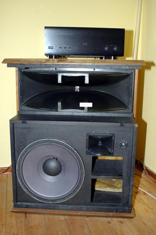
http://www.getcom.de/jbl/
(EV archive seems to be down at the moment)
BTW this perception of outstanding bass performance only happened twice - with *vented* cabinets - the other one was a english book shelf speaker (no recommendation for OB with its tiny 4" bass or so anyway
)Michael
Lynn Olson said:
By contrast, 15" paper-cone woofers are a well-known technology in continuous use since the early Thirties, and have a track record of working smoothly up to 1 kHz, and for a select few, even higher.
Hi Lynn
I got a lot of criticism for using a 15" driver up to 900 Hz - and I used a very good one. Its good to see someone who appreciates that the 15" is nearly the ideal size for maximum cone area with good high frequency capability. 18" have poor HF capability and 12" don't have much more high HF capability than a 15" but a lot less cone area. (All these depend on the specific drivers for for the groups as a whole this is true.)
- Home
- Loudspeakers
- Multi-Way
- Beyond the Ariel