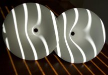
These things aren't easy to photograph thanks to complex internal contours and the silky-smooth internal finish. It's not glossy, but more of a satin finish, with a silky texture that is hard to describe. The junction to the compression driver looks perfect as far as I can tell, no burrs or flaws anywhere.
Attachments
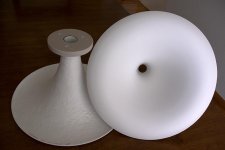
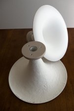
They're not as big as they look - they're actually kind of petite. Karna approves the looks, and so do I. Very elegant and classy looking, and also surprisingly rigid and solid. Much better made than the commercial horns I've seen, no burrs or flashing, and the rigidity is better too.
Attachments
") - anything else wouldn't be fair !!!
- anything else wouldn't be fair !!!drivers for ariel5s
hi lynn,
Thanks once again for your suggestions, i am actually dumping those drivers.... the other available 5.5 inch vifa driver is TC14WG49-08 ,
t/S parameters TC14WG49-08 are
nominal impedance-8 ohms
voice coil resistance- 5.55
nominal power(W) -35
short term power(w)- 110
operating power(W)- 10
sensitivity (db) -86
frequency range (hz) - 55 - 4000
free air resonance-53
voice coil diameter -25mm
voice coil height- 10mm
air gap height - 4mm
voice coil inductance(mh) - 0.60
effective diaphram area - 80 cm2
moving mass(g) - 78
magnet wt (g)/(oz)- 240/85
force factor(Bt) -- 5.2
Vas (l) - 10.5
Qms - 2.73
Qes - 0.53
Qts - 0.45
OTHER FEATURES:
NRSC cone
high linearity
low loss suspension
NR rubber surround
moulded rubber reinforced polymer chasis
vented magnet system
kindly tell me if this driver can be used for the ariel project...this is the only 5.5 inch driver of vifa available in india currently...and only a few nos are left cos they are closing down the distributership (corrson) cos the DIY volumes are very low......and the only other vifa driver available is 6.5 inch P17WJ-00-08, can it be used with cabinet modifications...kindly suggest......cos we are in a country which sucks for DIY audio fanatics...( I am very sorry to say that) .......kindly give suggestions...... thanks in advance
Re: drivers for ariel5s
Hi Variac, sorry we didn't get together. I was more mobile than last year, and was scampering around the show pretty much the whole time. As it was I only saw a tiny fraction of it, focussing mostly on the high-efficiency and dipole rooms.
The AH-425 overall diameter is 418 mm, and when resting on a flat surface, the part that contacts the surface is about 360 mm.
Plastic chassis - ugh. Have no idea what a "NRSC" cone is. The T/S figure of 78 grams is absurd - that's heavier than many 15" cones! It can't possibly be that heavy. The rest of the T/S data looks reasonable and typical for many 5.5" drivers.
Transmission lines, unlike vented speakers, are not picky about T/S parameters. The filling tends to wash out many differences between drivers, letting the line and stuffing dominate the picture. Aside from the improbable Mms figure, the rest looks fine.
What is not fine is the unknown frequency response. Unless it is ruler-flat with a very gradual and gentle rolloff with no peaks anywhere, you're on your own with the crossover. The basic concept with the Ariel was to chose the flattest and quickest CSD-decay drivers I could find back in the early Nineties, build an oversized MTM minimonitor around them, and arrange the efficiency of the paired midbass drivers so the tweeter wouldn't need to be attenuated.
As for the crossover, I voiced it with a slight "BBC dip" and a gentle tilt from bass to treble. That's pretty much it. Not a complicated system conceptually, and the many versions of the transmission line never sounded all that different from each other. I don't think all the complexity was warranted; I ever did a TL again, it would be much simpler.
I think it is basically impossible to build a good-sounding speaker without instrumentation - well, I couldn't do it, and I don't know anyone who can. The final "voicing" is done AFTER the system is measuring reasonably flat, NOT before, otherwise you'd endlessly go around in circles, never getting close to the optimum. There are many ways to build it wrong, but only a few to build it right - and professional speaker designers endlessly argue about which parameters to optimize.
Variac said:Lynn,
I was hoping to meet you at Rocky Mountain
About what is the diameter of the wide end?
Hi Variac, sorry we didn't get together. I was more mobile than last year, and was scampering around the show pretty much the whole time. As it was I only saw a tiny fraction of it, focussing mostly on the high-efficiency and dipole rooms.
The AH-425 overall diameter is 418 mm, and when resting on a flat surface, the part that contacts the surface is about 360 mm.
sujith kumar.r said:hi lynn,
Thanks once again for your suggestions, i am actually dumping those drivers.... the other available 5.5 inch vifa driver is TC14WG49-08,
t/S parameters TC14WG49-08 are
nominal impedance-8 ohms
voice coil resistance- 5.55
nominal power(W) -35
short term power(w)- 110
operating power(W)- 10
sensitivity (db) -86
frequency range (hz) - 55 - 4000
free air resonance-53
voice coil diameter -25mm
voice coil height- 10mm
air gap height - 4mm
voice coil inductance(mh) - 0.60
effective diaphram area - 80 cm2
moving mass(g) - 78
magnet wt (g)/(oz)- 240/85
force factor(Bt) -- 5.2
Vas (l) - 10.5
Qms - 2.73
Qes - 0.53
Qts - 0.45
OTHER FEATURES:
NRSC cone
high linearity
low loss suspension
NR rubber surround
moulded rubber reinforced polymer chasis
vented magnet system
Plastic chassis - ugh. Have no idea what a "NRSC" cone is. The T/S figure of 78 grams is absurd - that's heavier than many 15" cones! It can't possibly be that heavy. The rest of the T/S data looks reasonable and typical for many 5.5" drivers.
Transmission lines, unlike vented speakers, are not picky about T/S parameters. The filling tends to wash out many differences between drivers, letting the line and stuffing dominate the picture. Aside from the improbable Mms figure, the rest looks fine.
What is not fine is the unknown frequency response. Unless it is ruler-flat with a very gradual and gentle rolloff with no peaks anywhere, you're on your own with the crossover. The basic concept with the Ariel was to chose the flattest and quickest CSD-decay drivers I could find back in the early Nineties, build an oversized MTM minimonitor around them, and arrange the efficiency of the paired midbass drivers so the tweeter wouldn't need to be attenuated.
As for the crossover, I voiced it with a slight "BBC dip" and a gentle tilt from bass to treble. That's pretty much it. Not a complicated system conceptually, and the many versions of the transmission line never sounded all that different from each other. I don't think all the complexity was warranted; I ever did a TL again, it would be much simpler.
I think it is basically impossible to build a good-sounding speaker without instrumentation - well, I couldn't do it, and I don't know anyone who can. The final "voicing" is done AFTER the system is measuring reasonably flat, NOT before, otherwise you'd endlessly go around in circles, never getting close to the optimum. There are many ways to build it wrong, but only a few to build it right - and professional speaker designers endlessly argue about which parameters to optimize.
drivers for my ariel5s project
hi Lynn,
I am absolutely delighted and thankful for your prompt reply and suggestions... the moving mass Mms was 7.8 grams....that was an error ... I am attaching the complete data with the frequency response.....kindly advise...i am ever greatful to you...a man of iconic stature to reply to a diy novice like me....
Vifa driver for Sujith
FR:
http://www.tymphany.com/files/imagecache/product_graph/files/products/freq/TC14WG49-08.gif
Full PDF:
http://www.tymphany.com/files/products/pdf/TC14WG49-08.pdf
Link:
http://www.tymphany.com/tc14wg49-08
Sujith,
I would suggest following plans for an established kit, from such people/sites as:
http://www.zaphaudio.com (ZDT3.5, etc.)
http://www.linkwitzlab.com (Phoenix, Pluto, etc.)
http://www.madisound.com/catalog/index.php?cPath=35
etc.
You will have much more success with a tried-and-true design than attempting to recreate a discontinued/obsolete/unavailable speaker, however good. Without the original parts (as Lynn mentioned), anything produced cannot be the same as the original, and without the extensive experience and applied testing methodologies of Lynn, you will have a hard time producing a successful result.
Just my two cents...
-Tal
soongsc said:After looking at the data and reading the articles you have written, I can't help but wonder how things would look for an OS wave guide with a tube section before the throat would perform. Would very much like your opinion.
Not too good, I'm afraid. Attached is a simulation (simple model, not BEM) of a 90 degree included angle OS WG coupled to a 288B internal flare, compared with the wave guide by itself (in grey). The driver internal flare frequency is about 200Hz, and is not well terminated by the wave guide until about 2kHz. This causes quite strong reflections.
A conical horn would look similar attached to the 288B, but the ripple would be worse than for the OSWG above 3kHz or so. The change in flare rate at the driver exit is quite abrupt. Although it is less for the OSWG, in effect the problem is just moved a few cm towards the mouth.
For the record, the wave guide is placed in an infinite baffle, and does not have a radiused mouth. It has a throat diameter (not counting the driver internal flare) of 35.4mm, a mouth diameter of 375.4mm, and a length of 186.9mm.
A BEM simulation is currently running, to check the predictions of the simple model, and to see if there is any change in the directivity pattern between the waveguide alone and with driver flare included.
Bjørn
Attachments
Here is the on-axis frequency response for the two combinations, the red line is including the driver flare. Flat wavefront at the troat, uniform throat velocity of 1m/s, field point distance 3m from mouth.
Including the driver flare gives better LF response, but the cost is the powerful resonance at that frequency. I would not call this an improvement.
Bjørn
Including the driver flare gives better LF response, but the cost is the powerful resonance at that frequency. I would not call this an improvement.
Bjørn
Attachments
Since the acoustic impedance of the tube looked real straight theoretically, I'm planning on starting a series of testing with a wave guide, but also with some options for using different tube throats to see how it effects loading on a direct radiating driver. I did notice that wave guides might lower f0, so it would be interesting to see how the tube throat extension would change the loading.
- Home
- Loudspeakers
- Multi-Way
- Beyond the Ariel