Here's one of the Bjorn's models (not using the same BEM methodology shown above) that were used during the development of the AH-425. This shows the difference between a 420 and 440 Hz LeCleac'h horn with a T=0.707 and the internal profile of the Altec 288 as part of the model.
Attachments
salas said:So its a 40deg symmetrical dispersion horn at 3kHz? How high are you planning to go with it?
The target crossover is anywhere between 5 and 8 kHz, depending on the mass rolloff and onset of breakup of the compression driver, and the relative directivity of the AH-425/GPA-288 vs the RAAL 140-15D tweeter.
The HF directivity of the AH-160 and AH-425 are not likely to be the same, so the actual system will depend on what MLSSA (and direct audition) says is the best crossover. Like Dr. Geddes, I prefer to listen off-axis, and the crossovers will be balanced for that.
I don't have as much trouble with driver integration as others, so I'm not too troubled by that - but then, I've been wrestling with these things since 1975, and follow my instincts for what will and will not work. It's part of the reason I prefer passive crossovers - I can make very small adjustments to slope contours and inter-driver phase that aren't as easy with off-the-shelf active crossovers.
The main thing I look for is very careful control of inter-driver phase over at least an octave (and preferably wider) and avoidance of breakup artifacts close to the crossover region. Modern high-end speakers routinely fall into the this trap, with their fashionable minimalist 6 dB/octave crossovers combined with rigid diaphragms that have aggressive breakup products close to the crossover region - this results in poor system integration, regardless of pretty-looking polar curves, and very fatiguing sound in the upper midrange.
The $60,000 TAD Reference One, like so many other speakers in the ultra-high-end, has this problem - the coaxial mid/tweeter driver layout does not rescue the midrange from obvious upper-mid breakup and poor integration in the 1~5 kHz region. Classical music, with its broad and dense spectra, just doesn't work if the mid and HF have audible breakups in this region. Driver breakup, regardless of coaxial or MTM mounting, destroys crossover integration, no matter how clever the crossover design is.
I am much less concerned about polar curves than driver breakup - sorry if the Toole-school disciples are offended, but I don't agree with them on this issue. I put driver characteristics first and foremost in where to choose crossover frequencies, or if the driver is even suitable at all. The performance of the GPA 288 remains to be seen in this context, but I am optimistic based on what I've heard and measured so far. Similarly, the RAAL has a plenty of power-handling at the lower frequencies, unlike other ribbon tweeters.
Some designers work from the outside in, starting with a clean sheet of paper and a set of preferred parameters for the overall system. I work the other way around, finding the most attractive drivers I can get, and fit the system design to what the drivers can and can't do. It is clear that compression drivers (and horns) have less desirable behavior above mass rolloff, and that some diaphragm materials are preferable to others.
Re: Re: Results of Bjorn Kolbreks' BEM simulations
The model is just the horn, no driver parameters included. The horn is driven by a plane piston the size of the throat, with constant velocity.
It is simulated with the axisymmetric version of Stephen Kirkups
BEM package, using 6 elements pr wavelength.
Bjørn
John Sheerin said:Do you know how much of the driver that model includes?
The model is just the horn, no driver parameters included. The horn is driven by a plane piston the size of the throat, with constant velocity.
It is simulated with the axisymmetric version of Stephen Kirkups
BEM package, using 6 elements pr wavelength.
Bjørn
Lynn Olson said:I don't have as much trouble with driver integration...
...The main thing I look for is...
...It is clear that compression drivers (and horns) have less desirable behavior above mass rolloff, and that some diaphragm materials are preferable to others.
Lynn, this is what I call a thorough answer. Good luck again for fast results with no costly surprises.

Lynn Olson said:
Similarly, the RAAL has a plenty of power-handling at the lower frequencies, unlike other ribbon tweeters.
That`s because it is flat (non corrugated). I just finished my 1 meter tall ribbon and tried the "old fashioned corrugated" way and it sounded lifeless and with that typical nasty artificial high frequency sparkle and sizzle, common to all corrugated ribbons.
Then I just re tensioned the ribbons to the point of almost perfect flatness (the corrugations were still visible and contributed somewhat to the overall structural strength) and voila, a complete transformation of sound! The whole sound gained tremendously in control, weight and gone were the grayish sounding "sparkle and sizzle". Alexander is right, corrugated ribbons have no control in the lover passband of their operating range.
Now, you still want to get rid of that metal noise alu foils produce when totally flat, here embossed patterns help.
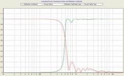
AH-550 Throat Impedance
The black line is the resistive term, the red line is the reactive term. The flat portion of the black line represents the region where the diaphragm of the driver is in constant-velocity mode (direct-radiators primarily operate in a constant-acceleration mode).
To expand on this point, constant-velocity drivers increase the diaphragm excursion at a rate of 6 dB/octave as the frequency is decreased, while constant-velocity drivers increase their excursion at a rate of 12 dB/octave as the frequency is decreased.
One of the most important functions of a crossover, aside from driver integration and equalization, is control of excursion. Many designers forget that direct-radiator tweeters operate in constant-acceleration mode, thus excursion continues to increase below the crossover point if a 6 dB/octave highpass filter is chosen. The tweeter is in the awkward situation where excursion continues to increase at a 6 dB/octave rate in the region between the crossover point and the Fs of the tweeter - excursion only decreases below Fs. Although the acoustic output of the tweeter is decreasing in the two-octave band between Fs and the crossover, the excursion is unfortunately increasing. (This is why I've always avoided 6 dB/octave crossovers, and prefer Gaussian or Bessel highpass filters of moderately higher order, typically 12 dB/octave.)
This unwanted increase in excursion is the source of an annoying intermittent distortion in many high-end loudspeakers with minimalist or linear-phase crossovers, since the tweeter excursion is excessive in the very critical 500 Hz to 2~3 kHz region. The problem is especially troublesome because orchestral music has the maximum spectral energy centered around 500 Hz, the same as the Fs of many tweeters.
Similarly, with a horn speaker crossover, the excursion curve has to be kept in mind - the excursion of the diaphragm increases many times once resistive horn loading is lost, which is why I'm seriously considering a notch filter tuned to the Fs of the compression driver - not so much as to twiddle with the response curve, but to keep unwanted out-of-band excursion to a mininum.
Attachments
Re: AH-550 BEM Simulation of Polar Pattern
Just a guesstimate, but looking at the dispersion pattern I'd say a highpass some where between 748 and 1262 (..the steeper the slope the lower the freq.).
Allow for a "rising response" on-axis (0 degree) and a targeted flat response to between 5000 and 6000 off-axis for the "listener's axis". Lowpass crossover between 5000 and 9000.
")
Lynn Olson said:
Run time for the AH-550 was 28 hours, simulated 100 Hz to 15 kHz in 250 steps. Here's the polar diagram:
Just a guesstimate, but looking at the dispersion pattern I'd say a highpass some where between 748 and 1262 (..the steeper the slope the lower the freq.).
Allow for a "rising response" on-axis (0 degree) and a targeted flat response to between 5000 and 6000 off-axis for the "listener's axis". Lowpass crossover between 5000 and 9000.
To expand on the point of the AH-550 post, many, if not most, modern high-end speakers suffer from poor excursion control of the tweeter - thanks to 6 dB/octave crossovers, or crossovers that are simply too low (so the polar pattern looks prettier) - combined with largely unfiltered upper-mid breakup from a rigid-diaphragm midrange or midbass driver. The result is harsh, grainy, and rough sound in the most critical part of the spectrum - 500 Hz to 5 kHz, something even a Sears Silvertone 5-tube AM table radio would get right.
This seems to be an almost generic problem - many of the rooms at the last RMAF had speakers with this obvious and rather gross combination of design defects. If you see me striding right past a room, speeding up as I go, that's why. These were problems I avoided in my first design back in 1975, so I'm not terribly sympathetic to seeing it become even more widespread a third of century later. This is why I grouse about "loss of knowledge" in the hifi biz.
This seems to be an almost generic problem - many of the rooms at the last RMAF had speakers with this obvious and rather gross combination of design defects. If you see me striding right past a room, speeding up as I go, that's why. These were problems I avoided in my first design back in 1975, so I'm not terribly sympathetic to seeing it become even more widespread a third of century later. This is why I grouse about "loss of knowledge" in the hifi biz.
Re: Re: AH-550 BEM Simulation of Polar Pattern
Yup, my thoughts too.
ScottG said:
Just a guesstimate, but looking at the dispersion pattern I'd say a highpass some where between 748 and 1262 (..the steeper the slope the lower the freq.).
Allow for a "rising response" on-axis (0 degree) and a targeted flat response to between 5000 and 6000 off-axis for the "listener's axis". Lowpass crossover between 5000 and 9000.
Yup, my thoughts too.
Similarly, with a horn speaker crossover, the excursion curve has to be kept in mind - the excursion of the diaphragm increases many times once resistive horn loading is lost, which is why I'm seriously considering a notch filter tuned to the Fs of the compression driver - not so much as to twiddle with the response curve, but to keep unwanted out-of-band excursion to a mininum.
If some padding is also needed, a simple resistor across the compression driver's terminals can be an elegant solution.
AH-425 bandwidth
Lynn, might well be that what you describe is closely related to Doppler distortion. Varying high frequency due to low frequency modulation as the membrane moves back and forth.
My latest spreadsheet version from January 2008 (downloadable from the footnote link) now includes import of HORNRESP simulation data or any measured data to calculate Doppler-IM distortion.
I did a quick calculation for your AH-425 with HORNRESP and imported the data into my spreadsheet.
Given a limit of 1% distortion at 120dB (which is just for to have some useful guideline) you either can go as low as HP = 850Hz / LP = 2800Hz whereas the limiting requirement for this is a XO slope as steep as a 3rd order Butterworth like seen in the upper right plot where the XO slope just touches the IM-barrier
*or* - if you want to push the upper frequency XO point to around 5 kHz the high pass frequency must move up to roughly 1500Hz.
To play around with that limits you have to set the bandwidth - respectively the XO points (entered into the yellow fields as "low frequency" and "high frequency") - such that the orange curve is always lower than the red curve in the upper right corner plot *and* the value of " IM at any frequency below " (in the calculated green field) stays at or below 1% / -40dB distortion.
For the values given above, I assumed a Sd of 44cm2 for the compression driver.
All the best with this beauties from Martin Seddon .
Bjørn – great simulations, wish I could do that ones too.
Greetings Michael
Lynn Olson said:
The target crossover is anywhere between 5 and 8 kHz, depending on the mass rolloff and onset of breakup of the compression driver, and the relative directivity of the AH-425/GPA-288 vs the RAAL 140-15D tweeter.
Lynn Olson said:
To expand on this point, constant-velocity drivers increase the diaphragm excursion at a rate of 6 dB/octave as the frequency is decreased, while constant-velocity drivers increase their excursion at a rate of 12 dB/octave as the frequency is decreased.
One of the most important functions of a crossover, aside from driver integration and equalization, is control of excursion. Many designers forget that direct-radiator tweeters operate in constant-acceleration mode, thus excursion continues to increase below the crossover point if a 6 dB/octave highpass filter is chosen. The tweeter is in the awkward situation where excursion continues to increase at a 6 dB/octave rate in the region between the crossover point and the Fs of the tweeter - excursion only decreases below Fs. Although the acoustic output of the tweeter is decreasing in the two-octave band between Fs and the crossover, the excursion is unfortunately increasing. (This is why I've always avoided 6 dB/octave crossovers, and prefer Gaussian or Bessel highpass filters of moderately higher order, typically 12 dB/octave.)
This unwanted increase in excursion is the source of an annoying intermittent distortion in many high-end loudspeakers with minimalist or linear-phase crossovers, since the tweeter excursion is excessive in the very critical 500 Hz to 2~3 kHz region. The problem is especially troublesome because orchestral music has the maximum spectral energy centered around 500 Hz, the same as the Fs of many tweeters.
Similarly, with a horn speaker crossover, the excursion curve has to be kept in mind - the excursion of the diaphragm increases many times once resistive horn loading is lost, which is why I'm seriously considering a notch filter tuned to the Fs of the compression driver - not so much as to twiddle with the response curve, but to keep unwanted out-of-band excursion to a mininum.
Lynn, might well be that what you describe is closely related to Doppler distortion. Varying high frequency due to low frequency modulation as the membrane moves back and forth.
My latest spreadsheet version from January 2008 (downloadable from the footnote link) now includes import of HORNRESP simulation data or any measured data to calculate Doppler-IM distortion.
I did a quick calculation for your AH-425 with HORNRESP and imported the data into my spreadsheet.
An externally hosted image should be here but it was not working when we last tested it.
Given a limit of 1% distortion at 120dB (which is just for to have some useful guideline) you either can go as low as HP = 850Hz / LP = 2800Hz whereas the limiting requirement for this is a XO slope as steep as a 3rd order Butterworth like seen in the upper right plot where the XO slope just touches the IM-barrier
*or* - if you want to push the upper frequency XO point to around 5 kHz the high pass frequency must move up to roughly 1500Hz.
To play around with that limits you have to set the bandwidth - respectively the XO points (entered into the yellow fields as "low frequency" and "high frequency") - such that the orange curve is always lower than the red curve in the upper right corner plot *and* the value of " IM at any frequency below " (in the calculated green field) stays at or below 1% / -40dB distortion.
For the values given above, I assumed a Sd of 44cm2 for the compression driver.
All the best with this beauties from Martin Seddon .
Bjørn – great simulations, wish I could do that ones too.
Greetings Michael
To go slightly deeper into what implies the above:
The outcome seen from a Doppler-IM perspective is two fold
First
- there is a minimal high pass XO slope limit. For horns it is generally more towards 3rd - 4th order in contrast to where its normally towards 2nd order with closed box'. You don't gain that much – in terms of HP corner frequency - if the slope is any steeper (well, you could go down to 450Hz(HP) / 900Hz(LP) with 6th order... ). Though it might be that Doppler modulation of *very* low frequencies may be more audible (kind of Darth Vader effect) and hence a > 4th order high pass may come out better. Don't know if anybody has any further experience with this.
Second
- there is an additional low pass XO frequency limit du to FM-IM aside from cone break up. This was bad news for me as well when John Kreskovsky pointed it out clearly somewhere back in this thread. You no longer can choose the upper XO free and independent from the lower XO point. There is a strong bandwidth limiting factor due to Doppler-intermodulation. Basically the maximal bandwidth is fixed – if moving the upper XO point (demanded by the following tweeter for example) the lower XO point *must* be re-adjusted accordingly (if you are at the IM limits).
The main difference between Doppler intermodulation and "normal" intermodulation is that it is basically a frequency modulation instead of amplitude modulation
Both can be seen completely independent from each other – though for real drivers both will overlap more or less.
Both, AM-IM *and* FM-IM have its routes in excessive diaphragm excursion
AM-IM raises when the voice coil leaves the homogeneous magnetic field and hence *is* motor dependent. Choose a better motor – more linear excursion in this case – and you can get off way better.
FM-IM raises when low frequency diaphragm excursion raises *and* when bandwidth is enlarged – it is completely *independent* from motor construction. Hence there is no way out by choosing any different motor (with the same Sd).
Greetings
Michael
PS:
Lynn or Bjørn, could you please post the frequency response of the AH-425. I'm not really familiar with HORNRESP and would like to have a check if my quick simu is somewhere realistic
The outcome seen from a Doppler-IM perspective is two fold
First
- there is a minimal high pass XO slope limit. For horns it is generally more towards 3rd - 4th order in contrast to where its normally towards 2nd order with closed box'. You don't gain that much – in terms of HP corner frequency - if the slope is any steeper (well, you could go down to 450Hz(HP) / 900Hz(LP) with 6th order...
). Though it might be that Doppler modulation of *very* low frequencies may be more audible (kind of Darth Vader effect) and hence a > 4th order high pass may come out better. Don't know if anybody has any further experience with this.Second
- there is an additional low pass XO frequency limit du to FM-IM aside from cone break up. This was bad news for me as well when John Kreskovsky pointed it out clearly somewhere back in this thread. You no longer can choose the upper XO free and independent from the lower XO point. There is a strong bandwidth limiting factor due to Doppler-intermodulation. Basically the maximal bandwidth is fixed – if moving the upper XO point (demanded by the following tweeter for example) the lower XO point *must* be re-adjusted accordingly (if you are at the IM limits).
The main difference between Doppler intermodulation and "normal" intermodulation is that it is basically a frequency modulation instead of amplitude modulation
Both can be seen completely independent from each other – though for real drivers both will overlap more or less.
Both, AM-IM *and* FM-IM have its routes in excessive diaphragm excursion
AM-IM raises when the voice coil leaves the homogeneous magnetic field and hence *is* motor dependent. Choose a better motor – more linear excursion in this case – and you can get off way better.
FM-IM raises when low frequency diaphragm excursion raises *and* when bandwidth is enlarged – it is completely *independent* from motor construction. Hence there is no way out by choosing any different motor (with the same Sd).
Greetings
Michael
PS:
Lynn or Bjørn, could you please post the frequency response of the AH-425. I'm not really familiar with HORNRESP and would like to have a check if my quick simu is somewhere realistic
mige0 said:Lynn or Bjørn, could you please post the frequency response of the AH-425. I'm not really familiar with HORNRESP and would like to have a check if my quick simu is somewhere realistic
The AH-425 sims are currently running, with some higher accuracy than the AH160 and AH550 sims. Expect some days waiting, BEM is heavy duty number crunching
At present I can't give the frequency response of the horn with the driver, but with some addition to my SW I can give you the pressure response with a constant velocity at the throat. However I will be away for some days, without any chance to do this. But it is a planned extension, so just be patient. I hope to write a BEM postprocessor that shows what you need to get a good idea of the performance of the horn. Much coding to do, though.
Later I hope to be able to use the BEM results to simulate the horn with driver, but that is still future. The BEM SW I'm working on is more or less a skeleton at the moment.
Mind that Hornresp only simulates the LeCléac'h horn to the 90 degree point. It will generally be a bit pessimistic for horns extending beyond that. Using BEM I have fund that extending the LeCléac'h contour to 270 degrees removes practially all the ripple in the throat impedance seen in the plots for the AH-160 and AH550.
Bjørn
Kolbrek said:
The AH-425 sims are currently running, with some higher accuracy than the AH160 and AH550 sims. Expect some days waiting, BEM is heavy duty number crunching
At present I can't give the frequency response of the horn with the driver, but with some addition to my SW I can give you the pressure response with a constant velocity at the throat. However I will be away for some days, without any chance to do this. But it is a planned extension, so just be patient. I hope to write a BEM postprocessor that shows what you need to get a good idea of the performance of the horn. Much coding to do, though.
Later I hope to be able to use the BEM results to simulate the horn with driver, but that is still future. The BEM SW I'm working on is more or less a skeleton at the moment.
Mind that Hornresp only simulates the LeCléac'h horn to the 90 degree point. It will generally be a bit pessimistic for horns extending beyond that. Using BEM I have fund that extending the LeCléac'h contour to 270 degrees removes practially all the ripple in the throat impedance seen in the plots for the AH-160 and AH550.
Bjørn
Thanks, Bjørn.
Only need the FR without driver.
Please don't feel forced - waiting for some more days or not shouldn't make the hell of a difference - this thread started one and a half years ago...
Kolbrek said:
Using BEM I have fund that extending the LeCléac'h contour to 270 degrees removes practially all the ripple in the throat impedance seen in the plots for the AH-160 and AH550.
Bjørn
Bjorn
I would concur with this as it is also what I have found through experience. What the "enclosure" does beyond 90 degrees can be very important to the resulting performance - even more so in the far field than on the impedance (which I generally don't care about). I can attest to the fact that an enclosure for the waveguide is far better than NOT having one and that the larger the face of this enclosure the better the performance. This should not surprise anyone. But since the face and the enclosure does have to be limited in size, it must have rounded edges as this too is a strong benefit. I really don't understand, from an acoustical point of view, why people do not enclose the waveguide. This is not a good thing for performance. But of course, if the appearance of the waveguide is a major attribute then "showing it" is probably desirable, but I would take sound quality over apperances any day - but maybe that's just me.
Some interesting findings about sound patterns of materials to build horns - and for sure valid not only for horns of course.
http://www.musique-concrete.com/Emat.htm
I'm experimenting with (very) shallow horns for the tweeter right now to get a seamless hand over in directivity.
For comfort and easy of doing I started with cutting expanded polystyrene.
I had to go up several dB with the tweeter to outweigh the subjectively loss of the upper frequencies due to the soft material and the pouros / rough surface – very annoying and a big surprise as well.
By accident I came across the page above outlining this same effect.
Greetings
Michael
- Home
- Loudspeakers
- Multi-Way
- Beyond the Ariel