Variac said:
On the back of the magnets?
I don't know why you want to do that, when you can easily use aluminum as the outside frame of the big woofers, and aluminum can not provide not only stiffness but also heat sinking ability.
Variac said:Another option is that each bass driver could use one of Nelson's current amps, which should improve the low end... [/B]
an array of F4?
But aren't we going back to the idea of a line level crossover? Maybe we need to incorporate a passive eq into the system -- something like a Pultec EQP1A.
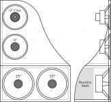
OK, I'm going to try and post a picture of what I've been thinking of - the centerline of the 12" coax driver is 40" high, the height of the OB is 48", and the depth of the bass module is 16". All dimensions are approximate, of course, and I expect I'll get a lot of firewood out of this project - too bad I don't have a fireplace to burn it in!
The key concept is the asymmetry of the left/right leakage path - preferably, a golden-section ratio, as it is for the 12" driver at the top, with a 7" path on the left side, and a 11.375" path on the right side. Various forms of bracing, such as SL's style of magnet bracing, are omitted for clarity. Besides, you guys are plenty smart, and can figure out how to damp panels and brace them.
The key concept is the asymmetry of the left/right leakage path - preferably, a golden-section ratio, as it is for the 12" driver at the top, with a 7" path on the left side, and a 11.375" path on the right side. Various forms of bracing, such as SL's style of magnet bracing, are omitted for clarity. Besides, you guys are plenty smart, and can figure out how to damp panels and brace them.
Attachments
Lynn Olson said:OK, I'm going to try and post a picture of what I've been thinking of - the centerline of the 12" coax driver is 40" high, the height of the OB is 48", and the depth of the bass module is 16". All dimensions are approximate, of course, and I expect I'll get a lot of firewood out of this project - too bad I don't have a fireplace to burn it in!
what about moving one or both 15" to the side panels? I also think you need more curves. I have been brainwashed by those Victoria's Secret commercials that curves are sexy.
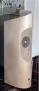
http://www.blackforestaudio.de/Helix2aWeb.jpg
Attachments
agent.5 said:
what about moving one or both 15" to the side panels?
Certainly an option, especially if you want to have four 15" drivers, two on the front, and two on the sides, with rods going between the side-mounted drivers to cancel vibration. Once you put the drivers facing each other, though, the lowpass filtering becomes more important, since the diaphragms are acoustically transparent and the drivers "see" each other. That sounds harmless enough until we get to the 1~2 mSec transit delay from driver to driver, which in turn creates peaks and dips at higher frequencies.
As a result, side-mounted drivers are partway to a "W" box in terms of box modes, so I'd reserve that option for the truly low bass content.
Lynn Olson said:
if you want to have four 15" drivers, two on the front, and two on the sides
I am thinking two 12" or 15" on the front but one mounted on top of another. I am thinking 12". With two 12" mid basses and one 12" mid, the front will have three 12" mounted vertically, and then two 15" on the sides.
Lynn Olson said:expect I'll get a lot of firewood out of this project - too bad I don't have a fireplace to burn it in!
Plywood doesn't make very good firewood...
dave
agent.5 said:
what about moving one or both 15" to the side panels? I also think you need more curves. I have been brainwashed by those Victoria Secret commercials that curves are sexy.
http://www.blackforestaudio.de/Helix2aWeb.jpg
Curves are cool, but hollow spaces are not our friend, especially at higher frequencies, where you get cavity resonances that are very difficult to remove. The whole point of an OB is to remove the reliance on damping materials that is so essential for box speakers. As we know, undamped boxes are unlistenable - but damped boxes still have plenty of box sound, just kind of muted and dull.
Damping materials have colorations of their own, something we want to avoid unless absolutely necessary. The horn guys are onto something by their avoidance of damping materials, which is a band-aid for problems elsewhere in the design.
agent.5 said:
I am thinking two 12" or 15" on the front but one mounted on top of another. I am thinking 12". With two 12" mid basses and one 12" mid, the front will have three 12" mounted vertically, and then two 15" on the sides.
With three drivers facing each other in the bass module, it's going to need good low-pass filtering so the mid-bass standing waves don't get into the audible range, but any kind of bass module (of reasonable size) is going to need a fair amount of EQ anyway.
The thing to remember is all drivers that are close to floor are going to create images of themselves, raising their efficiency. Same principle as a K-horn sitting in a corner, taking advantage of the sidewall, backwall, and floor reflections. In the mono days, a terrific idea for an unused corner, but a little more difficult when stereo came along.
agent.5 said:
I am thinking two 12" or 15" on the front but one mounted on top of another. I am thinking 12". With two 12" mid basses and one 12" mid, the front will have three 12" mounted vertically, and then two 15" on the sides.
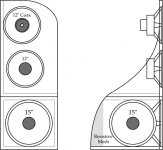
So, something a bit more like this? Front baffle is 18.375" wide, 48" high, and there are three woofers in the bass module. They'll need some fairly aggressive low-pass filtering to avoid the semi-box modes - but, as mentioned earlier, EQ is needed in this region anyway.
Attachments
Lynn Olson said:
So, something a bit more like this?
yes. Looks better already. I will add curves wherever I can (but i admit that I have no idea how it will affect how the speaker sounds). The front baffle and side wings are jointed at 90 degree. Maybe we can add something like a 6" roundover to the joint.
Maybe we can consult the plastic guy and see how much can be bent out of a piece of acrylic. The top front and side baffles can be made from one single piece of plastic, and eliminate an apparent joint.
agent.5 said:
yes. Looks better already. I will add curves wherever I can (but i admit that I have no idea how it will affect how the speaker sounds). The front baffle and side wings are jointed at 90 degree. Maybe we can add something like a 6" roundover to the joint.
Maybe we can consult the plastic guy and see how much can be bend out of a piece of acrylic. The top front and side baffles can be made from one single piece of plastic, and eliminate an apparent joint.
There's only one side wing, not two. That's a key design feature, along with the front-panel asymmetry. If the front panel is made of plastic, for sure you don't want to mount the drivers directly to it, but instead mount them on Linkwitz-style support structures with only a compliant gasket between the front baffle and the driver.
Lynn Olson said:
There's only one side wing, not two.
sorry. that was a typo and I can't edit post after 30 minutes.
From the drawing, it appears that you have the top front/side baffles for the 12" coaxial and 12" mid bass, and the bottom front/side baffles for the pair of 15".
I assume you are planning on having plastic on top and something else on the bottom, probably veneered MDF, unless it needs to function as heat sink, then some kind of aluminum/MDF concoction.
Lynn Olson said:I'm going to try and post a picture of what I've been thinking of - the centerline of the 12" coax driver is 40" high, the height of the OB is 48", and the depth of the bass module is 16".
Like this?
dave
Attachments
Just a few of thoughts:
With open alignments, given an equal construction 1 driver in front is worth 2 on the sides in the bass region. You have to think in terms of "D", the Differential in travel distance of the rear wave vs the front wave to the listening position.
The physical layout of the baffle also shapes the polar response. The axis angle(s) where the front and rear waves travel the same distance is where the region of greatest null occurs, so the shape that Lynn mentioned (wings on one side) could put the null where you don't want it.
In the low frequency section, parallel sides aren't really a concern. That's not the real source of resonance. Think about these long wavelength low frequency waves as sound bubbles expanding from the rear of the driver. With an open backed box type of shape, there just isn't sufficient expansion toward the sides to create resonance between the parallel walls.
The resonance of concern is based on the depth, essentially a 1/4 wave resonance. Unless you create unnecessarily large open cavities, damping is required for it to function properly. The purpose of the damping isn't in the traditional sense. It is to prevent the air mass in the cavity from acting as a lumped mass. At very long wavelengths the air moves in mass, making the terminus of the cavity your source for purposes of "D" and creating resonance as the transition occurs to more typical air behavior at higher frequency. Typical damping materials work, but so do things like staggered bracing.
Here's a pic of the bracing that drastically reduced resonance in my dual pathway cab, and that's with a 15" coax running full range in a 16" long pipe. Had I understood this resonance behavior when I built these a year ago, I may have used more extensive bracing.
An externally hosted image should be here but it was not working when we last tested it.
Is the shelf above the bass drivers required? It seems to be a pretty long ways to the top of the baffle in that location. That's not enough?
I suspect that two 12" drivers will go down lower than 300 hz. Is this a conservative estimate? a calc? or is it about the integration of the bass module?
John in CR has a big advantage here, he has actually done this stuff so should be given careful consideration.
P.S. please don't show more than 4 drivers- it's just too scary!
johninCR said:Just a few of thoughts:
With open alignments, given an equal construction 1 driver in front is worth 2 on the sides in the bass region. You have to think in terms of "D", the Differential in travel distance of the rear wave vs the front wave to the listening position.
The physical layout of the baffle also shapes the polar response. The axis angle(s) where the front and rear waves travel the same distance is where the region of greatest null occurs, so the shape that Lynn mentioned (wings on one side) could put the null where you don't want it.
In the low frequency section, parallel sides aren't really a concern. That's not the real source of resonance. Think about these long wavelength low frequency waves as sound bubbles expanding from the rear of the driver. With an open backed box type of shape, there just isn't sufficient expansion toward the sides to create resonance between the parallel walls.
The resonance of concern is based on the depth, essentially a 1/4 wave resonance. Unless you create unnecessarily large open cavities, damping is required for it to function properly. The purpose of the damping isn't in the traditional sense. It is to prevent the air mass in the cavity from acting as a lumped mass. At very long wavelengths the air moves in mass, making the terminus of the cavity your source for purposes of "D" and creating resonance as the transition occurs to more typical air behavior at higher frequency. Typical damping materials work, but so do things like staggered bracing.
All good points, drawn from hands-on experience. To visualize the cancellation null, I have to do the vector math, drawing out the location of the cancellation relative to the listener. I've also realized the panel on one side forms a short 90-degree horn, something I suspect is not particularly desirable. At the frequencies involved, pipelike structures may be more benign than I've thought - they are essentially very short transmission lines.
To answer the more general question from our gracious moderator, the top driver is going to be about -3 dB at 200 Hz, and the function of the other drivers is to extend the bass down to meet a stereo subwoofer at 60 ~ 80 Hz. A combination of EQ, staggered lowpass filters, and asymmetric panel width is what covers the gap between the subwoofer and the wideband driver.
Whether the midbass group of drivers are best driven from the fancy amp used for the wideband drivers or a separate bass amp is probably something best done by experience.
Let's just say I'm really motivated to get walking again as soon as possible, after following this discussion and thinking out loud with all of you. Thanks again for all the terrific input and great ideas!
- Home
- Loudspeakers
- Multi-Way
- Beyond the Ariel