altec 288c field coil
recently someone sold at ebay a Altec 288c transformed to field coil. It went for expensive money.Interesting the advantage the seller describes over the normal Altec driver.
There is a site on the internet dedicated to make field coil drivers DIY
Angelo
recently someone sold at ebay a Altec 288c transformed to field coil. It went for expensive money.Interesting the advantage the seller describes over the normal Altec driver.
There is a site on the internet dedicated to make field coil drivers DIY
Angelo
Richard C. Morgans - Horn Optimization
University of Adelaide:
Optimization Techniques for Horn-Loaded Speakers by Richard C. Morgans
Abstract, Table of Contents
Chapters 5 - 8
12th International Congress on Sound and Vibration:
The Sound Field at the Mouth of a Horn
by Morgans, Hansen, Zander, and Murphy
More Links to Technical Articles - thanks, Angelo!
Highly Recommended Book:
Loudspeakers for Music Recording and Reproduction by Philip Newell and Dr. Keith Holland, Lecturer at the Institute for Sound and Vibration Research at the University of Southampton.
Hi folks, just want to get your quick reaction.
I've been looking through the 2nd and 3rd harmonic distortion curves for the Beyma 18G50, the 18G550, and the 118Nd/w. I'm looking most closely at the 100 ~ 200 Hz region, and giving the 3rd harmonic about 10~15 dB more importance than the 2nd - which is nearly inaudible by comparison.
Based on those criteria, the 18G50 has notably low 3rd-harmonic distortion in the 100~400 Hz region, a remarkable -60 dB below the main signal - that's 0.1% distortion! True, the 2nd harmonic is substantially larger at -45 dB (about 0.5%), but the audibility of 2nd is much lower.
What undermines this cheery picture is looking at the distortion of the 18G550, a presumably similar driver. Now the 2nd and 3rd harmonic have changed places, with the 3rd harmonic gradually rising towards a peak around 450 Hz. Not so good - but of more concern, what constructional difference accounts for the reversal? A slightly misaligned voice coil that isn't quite centered in the gap? Or an outright mislabeling of the two harmonics - although this seems unlikely for a machine-generated graph.
Minor stuff, I know, but weird data like this sort of undermines confidence in the published information. Maybe the twin spiders are assembled slightly differently in the two drivers, and this shows up in the distortion data.
I was also looking at the BMS 18N850v2, with its very long Xmax figures. The distortion being measured at 1000 watts (!!!) makes it hard to compare to the Beyma figures measured at 1 watt - if drivers were amplifiers, the distortion could be approximately scaled by level, with 30 dB less drive level most likely yielding 30 dB lower distortion. But drivers do not behave like amplifiers, especially in terms of nonlinearities, so any guess of distortion at 1 watt is strictly a guess.
Paul W has been using the BMS 18N850 successfully in his quasi-cardioid speakers, so there's one vote of confidence for this driver - and it has attracted favorable comment over in the Subwoofer forum as well. Assistance Audio is selling them for US$350 each, which isn't a bad price for something on this performance level.
P.S. I haven't forgotten the TD drivers, but I don't have the nerve to commission a custom 18" driver before the design gets more solid. I'll try the off-the-shelf pro stuff first and see how it works out.
Lynn Olson said:Hi folks, just want to get your quick reaction.
I've been looking through the 2nd and 3rd harmonic distortion curves for the Beyma 18G50, the 18G550, and the 118Nd/w. I'm looking most closely at the 100 ~ 200 Hz region, and giving the 3rd harmonic about 10~15 dB more importance than the 2nd - which is nearly inaudible by comparison.
Based on those criteria, the 18G50 has notably low 3rd-harmonic distortion in the 100~400 Hz region, a remarkable -60 dB below the main signal - that's 0.1% distortion! True, the 2nd harmonic is substantially larger at -45 dB (about 0.5%), but the audibility of 2nd is much lower.
What undermines this cheery picture is looking at the distortion of the 18G550, a presumably similar driver. Now the 2nd and 3rd harmonic have changed places, with the 3rd harmonic gradually rising towards a peak around 450 Hz. Not so good - but of more concern, what constructional difference accounts for the reversal? A slightly misaligned voice coil that isn't quite centered in the gap? Or an outright mislabeling of the two harmonics - although this seems unlikely for a machine-generated graph.
Minor stuff, I know, but weird data like this sort of undermines confidence in the published information. Maybe the twin spiders are assembled slightly differently in the two drivers, and this shows up in the distortion data.
I was also looking at the BMS 18N850v2, with its very long Xmax figures. The distortion being measured at 1000 watts (!!!) makes it hard to compare to the Beyma figures measured at 1 watt - if drivers were amplifiers, the distortion could be approximately scaled by level, with 30 dB less drive level most likely yielding 30 dB lower distortion. But drivers do not behave like amplifiers, especially in terms of nonlinearities, so any guess of distortion at 1 watt is strictly a guess.
Paul W has been using the BMS 18N850 successfully in his quasi-cardioid speakers, so there's one vote of confidence for this driver - and it has attracted favorable comment over in the Subwoofer forum as well. Assistance Audio is selling them for US$350 each, which isn't a bad price for something on this performance level.
P.S. I haven't forgotten the TD drivers, but I don't have the nerve to commission a custom 18" driver before the design gets more solid. I'll try the off-the-shelf pro stuff first and see how it works out.
With ARTA I have measured 3 different Beyma drivers and they all measure nearly the same as the what they publish in response, distortion and impedance.
IOW I have found them to be consistent with my little stash.
My experience with Beyma drivers is they also sound good and are well made.
Hope this helps.
Lynn Olson said:
What undermines this cheery picture is looking at the distortion of the 18G550, a presumably similar driver. Now the 2nd and 3rd harmonic have changed places, with the 3rd harmonic gradually rising towards a peak around 450 Hz. Not so good - but of more concern, what constructional difference accounts for the reversal? A
The labels are not computer generated in all likelihood - the distortion labels are wrong on the 18G50 graphs. Look at where the peak in the distortion is versus where the peak in response in the fundamental is. There will typically be a peak in HD2 at half of a peak in the fundamental response and a peak in HD3 at 1/3 of a peak in the fundamental response, as the fundamental response is raising the level of those harmonics.
In general, the distortion spectrum could be changed by using different spiders, surround geometries, magnetic system geometries - without seeing the BL, Cms and Le vs x curves, it's tough to say if they're the same or not.
Re: Richard C. Morgans - Horn Optimization
Lynn - thanks for this, a fascinating study. I will have to get the whole paper. The first person that I have read that understands the problem.
Lynn Olson said:
University of Adelaide:
Optimization Techniques for Horn-Loaded Speakers by Richard C. Morgans
Lynn - thanks for this, a fascinating study. I will have to get the whole paper. The first person that I have read that understands the problem.
Lynn Olson said:
P.S. I haven't forgotten the TD drivers, but I don't have the nerve to commission a custom 18" driver before the design gets more solid. I'll try the off-the-shelf pro stuff first and see how it works out.
Hi Lynn,
I actually have everything in line here for an 18" driver, minus a phase plug. That may or may not be quick to get done here but is the only thing holding up the process. I have a surround that will do 18mm and am planning for a driver in the range of 13-14mm Xmax. Should be able to have something easily in the range of 95dB or more with the full copper sleeve on the pole.
John
Should be able to have something easily in the range of 95dB or more with the full copper sleeve on the pole.
I hope this is not off-topic. The copper sleeve also covers the top of the pole piece? (as visible from the phase plug?). And what is the thickness you discovered to be the best trade-off in terms of demodulating the flux/maintaining the efficiency?
Also I've noticed that other manufacturers are using demodulating rings (al or cu) in the gap, but not on the pole piece, rather on the front plate/motor pot side. What is your experience with this.
I hope I am not getting too much into design/technical details, but I find these things interesting.
Thank you!
SunRa said:
I hope this is not off-topic. The copper sleeve also covers the top of the pole piece? (as visible from the phase plug?). And what is the thickness you discovered to be the best trade-off in terms of demodulating the flux/maintaining the efficiency?
Also I've noticed that other manufacturers are using demodulating rings (al or cu) in the gap, but not on the pole piece, rather on the front plate/motor pot side. What is your experience with this.
I hope I am not getting too much into design/technical details, but I find these things interesting.
Thank you!
Well I can't give away all of our secrets.
") In reality, the thicker you can go to get the Bl you need, the better it is. We use all Ceramic 5 or Y35 magnets if you go by chinese grade numbers. Most companies use Y30 because they are about 20% cheaper, but also 10% less strength. By doing this, we get back about an extra 10% in flux in the gap, and then turn down the pole and apply copper until we get back to where we want to be. It's all tradeoffs and optimizing what we need. The higher the Bl you start out with the better, as it means you can add more copper.
In reality, the thicker you can go to get the Bl you need, the better it is. We use all Ceramic 5 or Y35 magnets if you go by chinese grade numbers. Most companies use Y30 because they are about 20% cheaper, but also 10% less strength. By doing this, we get back about an extra 10% in flux in the gap, and then turn down the pole and apply copper until we get back to where we want to be. It's all tradeoffs and optimizing what we need. The higher the Bl you start out with the better, as it means you can add more copper.The sleeve covers the entire pole, and the pole is extended from .5" to 1" past the top plate, depending on the driver and excursion. Having the shorting ring directly in the gap is by far the most effective at reducing distortion and inductance vs at the bottom of the pole, or above and below the top plate. Putting it on the entire pole keeps inductance more linear, as even when the coil begins to run out of the gap upwards or downwards, it is still next to the same amount of copper. If you simply do this on the ID of the gap plate, as your coil begins to ride out of the gap, it is near less and less of the shorting ring the farther it goes and as a result inductance is not linear.
John
Re: Richard C. Morgans - Horn Optimization
You're welcome - good paper, isn't it? Most of it far above my head, but it's clear the author has done a thorough analysis - a little reminiscent of the original Richard Small doctoral thesis papers. Have to give credit to Australian Universities for supporting audio research.
Dr. Geddes, I was wondering about one of the things you mentioned over in the Waveguide thread. Perhaps I misread it, but it appeared that a major source of HOM's was simply the fact the throat size was nonzero - in other words, the smaller the throat, the less the HOM's. Is this a correct reading?
In traditional horn theory, second-order nonlinear distortion is assumed to primarily originate from the throat geometry, but as described in the 2002 Voishvillo paper, the major source of second-order air nonlinearity is actually between the diaphragm and the rear surface of the phase plug, and other small-dimension parts of the phase plug.
If throat size is an open variable, and you had a free hand designing the phase plug, would smaller throats have better performance in an OS waveguide - say, half or quarter-inch? Or would that be flirting with second-order distortion from air nonlinearities?
John Sheerin and John Janowitz, thanks for the commentary about the distortion curves of the Beyma drivers. 0.1% third-harmonic distortion at 95 dB SPL seemed too good to be true. That puts the BMS 18N850 in a more favorable light, particularly considering the astonishing drive level. You could actually plug the 18N850 into the wall in North America (1800 watts at 60 Hz and 120V RMS) and it would survive for a little while. I wouldn't want to be in the same town, though.
As for a potential TD 18-incher, I'd vote for 40~50 mm Xdamage, as with the Beyma and BMS drivers. It would be nice not to have to babysit the driver against wayward LF content from movies or techno CD's. Performance somewhere in the Beyma and BMS league would be desirable (highish Fs, Qts, and efficiency), and I'd vote for silicone/Aquaplas-damped double spiders to minimize undesirable side-to-side rocking modes. Double spiders also offer the option of push-pull distortion cancellation by reverse-mounting one of them, which seems like a clever and easy-to-do idea.
One of the things I'll be mentioning to Great Plains Audio is applying Aquaplas (now called Antivibe) to the tangential surround of the aluminum compression driver diaphragm. JBL applies Aquaplas/Antivibe to the whole diaphragm when you buy a 435Be, but I feel this is a mistake. The part of the diaphragm with the most chaotic radiation is obviously the surround, and it's an area where mass-damping and outright suppression of radiation is desirable. That is NOT true of the diaphragm dome, where low-as-possible mass and uniform emission into the phase plug assembly are primary goals. Raising the mass of the diaphragm is extremely undesirable, since it depresses efficiency and decreases HF extension.
Since the dome of the diaphragm and its surround operate in completely different ways, and in fact have completely different functions, it only makes sense to treat them differently, rather than applying damping goo to the whole thing. Adding a bit of mass damping to the surround seems like a good idea, and is likely to improve the mechanical termination between the moving diaphragm and stationary mounting ring.
gedlee said:
Lynn - thanks for this, a fascinating study. I will have to get the whole paper. The first person that I have read that understands the problem.
You're welcome - good paper, isn't it? Most of it far above my head, but it's clear the author has done a thorough analysis - a little reminiscent of the original Richard Small doctoral thesis papers. Have to give credit to Australian Universities for supporting audio research.
Dr. Geddes, I was wondering about one of the things you mentioned over in the Waveguide thread. Perhaps I misread it, but it appeared that a major source of HOM's was simply the fact the throat size was nonzero - in other words, the smaller the throat, the less the HOM's. Is this a correct reading?
In traditional horn theory, second-order nonlinear distortion is assumed to primarily originate from the throat geometry, but as described in the 2002 Voishvillo paper, the major source of second-order air nonlinearity is actually between the diaphragm and the rear surface of the phase plug, and other small-dimension parts of the phase plug.
If throat size is an open variable, and you had a free hand designing the phase plug, would smaller throats have better performance in an OS waveguide - say, half or quarter-inch? Or would that be flirting with second-order distortion from air nonlinearities?
John Sheerin and John Janowitz, thanks for the commentary about the distortion curves of the Beyma drivers. 0.1% third-harmonic distortion at 95 dB SPL seemed too good to be true. That puts the BMS 18N850 in a more favorable light, particularly considering the astonishing drive level. You could actually plug the 18N850 into the wall in North America (1800 watts at 60 Hz and 120V RMS) and it would survive for a little while. I wouldn't want to be in the same town, though.
As for a potential TD 18-incher, I'd vote for 40~50 mm Xdamage, as with the Beyma and BMS drivers. It would be nice not to have to babysit the driver against wayward LF content from movies or techno CD's. Performance somewhere in the Beyma and BMS league would be desirable (highish Fs, Qts, and efficiency), and I'd vote for silicone/Aquaplas-damped double spiders to minimize undesirable side-to-side rocking modes. Double spiders also offer the option of push-pull distortion cancellation by reverse-mounting one of them, which seems like a clever and easy-to-do idea.
One of the things I'll be mentioning to Great Plains Audio is applying Aquaplas (now called Antivibe) to the tangential surround of the aluminum compression driver diaphragm. JBL applies Aquaplas/Antivibe to the whole diaphragm when you buy a 435Be, but I feel this is a mistake. The part of the diaphragm with the most chaotic radiation is obviously the surround, and it's an area where mass-damping and outright suppression of radiation is desirable. That is NOT true of the diaphragm dome, where low-as-possible mass and uniform emission into the phase plug assembly are primary goals. Raising the mass of the diaphragm is extremely undesirable, since it depresses efficiency and decreases HF extension.
Since the dome of the diaphragm and its surround operate in completely different ways, and in fact have completely different functions, it only makes sense to treat them differently, rather than applying damping goo to the whole thing. Adding a bit of mass damping to the surround seems like a good idea, and is likely to improve the mechanical termination between the moving diaphragm and stationary mounting ring.
The Pyle website does not have T/S parameters for the PDW21250 that Magnetar uses. If anyone gets a manual from Pyle, would you post T/S data...Thanks...
Current limited specs......
Model PDW21250
Brand PylePro
21'' High Power Subwoofer
8 Ohm Impedance
1000W RMS/2000W Peak Power
22 Hz Resonance
Frequency Response: 22 Hz - 4K Hz
Sensitivity: 1W@1M: 107 dB
Magnet Weight: 350 Oz
4'' Aluminum Voice Coil
Diameter: 21.8''
Mounting Depth: 10.2''
Die-Cast Aluminum Frame LJD
Umm - 22 Hz Fs and 107 dB efficiency? Is this a car-stereo specification?
Can I buy a Flux Capacitor as an option if I feel in the mood for time travel?
Can I buy a Flux Capacitor as an option if I feel in the mood for time travel?
Lynn Olson said:Umm - .. 107 dB efficiency?
Naw.. Thats the nasty peak at 1.7 kHz that you have been trying to avoid.
Re: Re: Richard C. Morgans - Horn Optimization
Hi Lynn,
A few things regarding Xdamage. To me, Xdamage is the point at which you can bottom the VC on the back plate actually causing damage to the driver. Xmax is the magnetic limit at which the BL curve drops to 70% of the rest value. Xsus is the useable suspension limit before Kms goes way up. That said, the surround we use is the same as the surround from the EVX180B's. They specify Xlim of 25mm. I'm not sure if that Xlim is their damage point, or the limit of the suspension travel. That surround IMO should but Xsus at 18-20mm, although they claim it can move farther. We have about 42mm physical one way travel before the coil can ever hit the back plate. Quite simply you can never bottom the coil without tearing up the suspension. Also by the time you get to 20mm, the Bl is dropped to only around 30-40% of what it is at the rest value. This means you'd need enormous amounts of power at those excursions to push the driver far enough to damage itself.
So, this leads to a few options. We would do 2.5" VC versions of all the current TD motors, but in the 18" size. A 4 layer flat copper, 4 layer flat alum, and 4 layer round copper will all be options at this point. All in the 14mm Xmax range. Expect these to be in the 96-98dB range. A midrange option with shorter light coil will be just upwards of 100dB. Then the high Xmax version will have 22mm Xmax, 30mm one way suspension travel and 34mm physical clearance inside the motor and around 93-94dB. TC sounds had a progressive roll cloth surround that would do 32mm or so quite well. For most applications though, the 14mm Xmax models will be quite sufficient.
Regarding the spiders, the push pull mounting of 2 spiders does help reduce non-linearity. The problem in most all cases is making it fit in a frame. Standard frames are often a standard depth. For example, EV, Eminence, Beyma, etc cones all drop right into our standard cone and the spiders line up height wise perfectly.Stacking too spiders directly on top of each other will cause all kinds of issues with them rubbing and wearing, so you need space between them. Since the spider can't go down, the cone has to be made more shallow. That now gets into tooling a totally new cone and all the issues involved in that. Also, having space on the VC form between the cone and spider, or between multiple spiders introduces another point of resonance. In an 18" driver it would be much higher in frequency and not be an issue in the useable bandwidth, but in other drivers it can be.
Also of interest is that in a traditional woven material, most non-linearity comes from the weave in the material itself. You can have up to 300% variance in the linearity around the diameter of the spider due to the way the weave goes. Now if you stack too spiders and put the weave at a 45degree angle to the one above/below you help to cancel this out. Aligning the two with the weave in line with the other one multiplies this nonlinearity. A non-woven cloth for a spider is much better, although not readily available yet. We've been waiting on someone to get this closer to production ready for awhile. For damping, we have spent a lot of time working to get rid of any issues with resonances on cones and surrounds. CP Moyen makes many dampers that can be used on cloth surrounds, spiders, etc. Spiders have not proven to be a major issue in most cases. If you can identify bumps in the impedance curve with corresponding bumps in the response curve, you can typically trace them down to cone resonance, surround, spider, etc. However if you don't see these issues, simply coating a spider may do more harm than good. The more porous the spider, the more heat can escape through it.
John
Lynn Olson said:
As for a potential TD 18-incher, I'd vote for 40~50 mm Xdamage, as with the Beyma and BMS drivers. It would be nice not to have to babysit the driver against wayward LF content from movies or techno CD's. Performance somewhere in the Beyma and BMS league would be desirable (highish Fs, Qts, and efficiency), and I'd vote for silicone/Aquaplas-damped double spiders to minimize undesirable side-to-side rocking modes. Double spiders also offer the option of push-pull distortion cancellation by reverse-mounting one of them, which seems like a clever and easy-to-do idea.
Hi Lynn,
A few things regarding Xdamage. To me, Xdamage is the point at which you can bottom the VC on the back plate actually causing damage to the driver. Xmax is the magnetic limit at which the BL curve drops to 70% of the rest value. Xsus is the useable suspension limit before Kms goes way up. That said, the surround we use is the same as the surround from the EVX180B's. They specify Xlim of 25mm. I'm not sure if that Xlim is their damage point, or the limit of the suspension travel. That surround IMO should but Xsus at 18-20mm, although they claim it can move farther. We have about 42mm physical one way travel before the coil can ever hit the back plate. Quite simply you can never bottom the coil without tearing up the suspension. Also by the time you get to 20mm, the Bl is dropped to only around 30-40% of what it is at the rest value. This means you'd need enormous amounts of power at those excursions to push the driver far enough to damage itself.
So, this leads to a few options. We would do 2.5" VC versions of all the current TD motors, but in the 18" size. A 4 layer flat copper, 4 layer flat alum, and 4 layer round copper will all be options at this point. All in the 14mm Xmax range. Expect these to be in the 96-98dB range. A midrange option with shorter light coil will be just upwards of 100dB. Then the high Xmax version will have 22mm Xmax, 30mm one way suspension travel and 34mm physical clearance inside the motor and around 93-94dB. TC sounds had a progressive roll cloth surround that would do 32mm or so quite well. For most applications though, the 14mm Xmax models will be quite sufficient.
Regarding the spiders, the push pull mounting of 2 spiders does help reduce non-linearity. The problem in most all cases is making it fit in a frame. Standard frames are often a standard depth. For example, EV, Eminence, Beyma, etc cones all drop right into our standard cone and the spiders line up height wise perfectly.Stacking too spiders directly on top of each other will cause all kinds of issues with them rubbing and wearing, so you need space between them. Since the spider can't go down, the cone has to be made more shallow. That now gets into tooling a totally new cone and all the issues involved in that. Also, having space on the VC form between the cone and spider, or between multiple spiders introduces another point of resonance. In an 18" driver it would be much higher in frequency and not be an issue in the useable bandwidth, but in other drivers it can be.
Also of interest is that in a traditional woven material, most non-linearity comes from the weave in the material itself. You can have up to 300% variance in the linearity around the diameter of the spider due to the way the weave goes. Now if you stack too spiders and put the weave at a 45degree angle to the one above/below you help to cancel this out. Aligning the two with the weave in line with the other one multiplies this nonlinearity. A non-woven cloth for a spider is much better, although not readily available yet. We've been waiting on someone to get this closer to production ready for awhile. For damping, we have spent a lot of time working to get rid of any issues with resonances on cones and surrounds. CP Moyen makes many dampers that can be used on cloth surrounds, spiders, etc. Spiders have not proven to be a major issue in most cases. If you can identify bumps in the impedance curve with corresponding bumps in the response curve, you can typically trace them down to cone resonance, surround, spider, etc. However if you don't see these issues, simply coating a spider may do more harm than good. The more porous the spider, the more heat can escape through it.
John
Lynn Olson said:Umm - 22 Hz Fs and 107 dB efficiency? Is this a car-stereo specification?
Can I buy a Flux Capacitor as an option if I feel in the mood for time travel?
ScottG said:
Naw.. Thats the nasty peak at 1.7 kHz that you have been trying to avoid.
Of course it is not true (107 db) but I'm willing to bet you both 100 US Federal Reserve Notes you will not find a better bass driver to be used on an open baffle for under 150 US Federal Reserve Notes. LOL -
Now go back to your 'beyond the oreo' fantasies!

Re: Re: Richard C. Morgans - Horn Optimization
A good 18" driver will have .1 percent distortion above 40 cycles at higher levels then that! Try a JBL 2242 in a horn - LOL "too good to be true" Maybe some time next year we will see your graphs ????
Lynn Olson said:
John Sheerin and John Janowitz, thanks for the commentary about the distortion curves of the Beyma drivers. 0.1% third-harmonic distortion at 95 dB SPL seemed too good to be true. That puts the BMS 18N850 in a more favorable light, particularly considering the astonishing drive level. You could actually plug the 18N850 into the wall in North America (1800 watts at 60 Hz and 120V RMS) and it would survive for a little while. I wouldn't want to be in the same town, though.
A good 18" driver will have .1 percent distortion above 40 cycles at higher levels then that! Try a JBL 2242 in a horn - LOL "too good to be true" Maybe some time next year we will see your graphs ????
Re: Re: Richard C. Morgans - Horn Optimization
I read the whole paper and he didn't quite get the history right. He must have gotten my book about 1/2 way through the thesis because there is no mention of it in chapters 1-3 and in fact much of what he talks about there is described in my book, but he doesn't reference it. Then by the later chapters he is taking things directly from the book. I found this confusing until I realized that the book would have come out right in the middle of his project, so I guess its natural that he picks it up in the middle.
The one thing that he does not point out is that his optimization is for a waveguide in a sphere. He might find different results for different enclosure geometries. This is the problem with his approach - it is very specific for a very specific situation.
The part of his experimental data that got my attention was how often the mouth velocities were non-axi-symmetric. I have wondered about this and expected it would be the case and his data clearly shows that it is - or can be.
Morgan is also the only other person that I have read that recognizes that HOMs can have an evanescent aspect to them. He got a lot of things right, although his major contribution was in technique rather than specific designs. His "best" designs all looked like OS waveguides with some slight modifications at the mouth. This certainly wasn't new to me. He also seemed pretty clear on the goal - constant directivity with frequency. I'm afraid that the horns that you have choosen don't have this feature. Constant directivity does not apear to be a major requirement for all designers.
I'm not sure that one can say that there is a major source of HOMs because there are many sources and the contributions will differ with the specific situation. The smaller the throat the higher the cut-in frequency for the HOMs, so in a sense, yes the smaller the throat the fewer HOMs there will be IN GENERAL, but not necessarily always.
Lynn Olson said:
You're welcome - good paper, isn't it? Most of it far above my head, but it's clear the author has done a thorough analysis - a little reminiscent of the original Richard Small doctoral thesis papers. Have to give credit to Australian Universities for supporting audio research.
Dr. Geddes, I was wondering about one of the things you mentioned over in the Waveguide thread. Perhaps I misread it, but it appeared that a major source of HOM's was simply the fact the throat size was nonzero - in other words, the smaller the throat, the less the HOM's. Is this a correct reading?
I read the whole paper and he didn't quite get the history right. He must have gotten my book about 1/2 way through the thesis because there is no mention of it in chapters 1-3 and in fact much of what he talks about there is described in my book, but he doesn't reference it. Then by the later chapters he is taking things directly from the book. I found this confusing until I realized that the book would have come out right in the middle of his project, so I guess its natural that he picks it up in the middle.
The one thing that he does not point out is that his optimization is for a waveguide in a sphere. He might find different results for different enclosure geometries. This is the problem with his approach - it is very specific for a very specific situation.
The part of his experimental data that got my attention was how often the mouth velocities were non-axi-symmetric. I have wondered about this and expected it would be the case and his data clearly shows that it is - or can be.
Morgan is also the only other person that I have read that recognizes that HOMs can have an evanescent aspect to them. He got a lot of things right, although his major contribution was in technique rather than specific designs. His "best" designs all looked like OS waveguides with some slight modifications at the mouth. This certainly wasn't new to me. He also seemed pretty clear on the goal - constant directivity with frequency. I'm afraid that the horns that you have choosen don't have this feature. Constant directivity does not apear to be a major requirement for all designers.
I'm not sure that one can say that there is a major source of HOMs because there are many sources and the contributions will differ with the specific situation. The smaller the throat the higher the cut-in frequency for the HOMs, so in a sense, yes the smaller the throat the fewer HOMs there will be IN GENERAL, but not necessarily always.
Re: Re: Richard C. Morgans - Horn Optimization
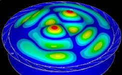
Do you have any data to back this up? I remembered a FEA run I did about three years ago on a tangential surround diaphragm assembly. I went back and looked at it again. It was modeled in 3D to get the tangential compliance, so I didn't do an acoustic simulation, but I did look at the mechanical modes. I looked at the first 100 modes and did not find one where the surround was significantly resonating in any way. This covered almost 1 decade of response. Note that this geometry is not the 288 geometry. It also may be that all the modes I looked at do not contribute significantly to the output of the driver - I was looking at shape, not magnitude. It may also be that the surround resonance is the only secondary resonance that really does contribute to the output of the driver, but personally I'm not convinced of this for the tangential surround shape. Now if you have a direct radiator with a surround that's much softer than the diaphragm, sure, the surround will have some issues. Or if you have a compression driver that uses a surround that's made of a softer material than the dome. Anyway, I'd be very interested if you have some information on this.
For example, mode 53 (about 5 times resonance). Color scale is displacement - blue is zero, red is max.
Lynn Olson said:
to the tangential surround of the aluminum compression driver diaphragm. JBL applies Aquaplas/Antivibe to the whole diaphragm when you buy a 435Be, but I feel this is a mistake. The part of the diaphragm with the most chaotic radiation is obviously the surround, and it's an area where mass-damping and outright suppression of radiation is desirable. That is NOT true of the diaphragm dome, where low-as-possible mass and uniform emission into the phase plug assembly are primary goals. Raising the mass of the diaphragm is extremely undesirable, since it depresses efficiency and decreases HF extension.
Do you have any data to back this up? I remembered a FEA run I did about three years ago on a tangential surround diaphragm assembly. I went back and looked at it again. It was modeled in 3D to get the tangential compliance, so I didn't do an acoustic simulation, but I did look at the mechanical modes. I looked at the first 100 modes and did not find one where the surround was significantly resonating in any way. This covered almost 1 decade of response. Note that this geometry is not the 288 geometry. It also may be that all the modes I looked at do not contribute significantly to the output of the driver - I was looking at shape, not magnitude. It may also be that the surround resonance is the only secondary resonance that really does contribute to the output of the driver, but personally I'm not convinced of this for the tangential surround shape. Now if you have a direct radiator with a surround that's much softer than the diaphragm, sure, the surround will have some issues. Or if you have a compression driver that uses a surround that's made of a softer material than the dome. Anyway, I'd be very interested if you have some information on this.
For example, mode 53 (about 5 times resonance). Color scale is displacement - blue is zero, red is max.
Attachments
The reference is Murray and Durbin of JBL, published in 1979. Since the results appear to depend on small manufacturing tolerance errors, it's a good question how repeatable they would be. The claim that the JBL diamond suspension is more immune to these variations is not backed up by the data shown in this paper - only one example of the new suspension is shown.
The reasons for JBL to convert over to the diamond suspension (as opposed to tangential) are not very clear. This was the same time that diaphragms were failing in stadium rock applications, and in movie theaters that were using the new Acousta-Voicing equalization system. JBL switched to diamond suspension and titanium, while Altec switched to a different aluminum alloy (Pascalite) and retained the tangential suspension that went back to the WECO days.
Emilar (now Radian) retained the traditional aluminum diaphragm and used a plastic (Mylar) surround. My limited understanding of the situation with soft surrounds is that they can be prone to rocking modes (this is certainly true in direct-radiator midrange domes) and may have unexpected dips and peaks at the bottom of the working range.
- Home
- Loudspeakers
- Multi-Way
- Beyond the Ariel