I'm trying to use the minidsp 2x4 I2S input, I need some help
I'm using the default master configuration
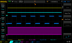
I've connected a 4ch scope to connector P2, see attached:
- yellow probe to pin 15, IN_BCLK. voltage seems to be a fixed 3.3V
- light blue probe to pin 14, IN_LRCLK, voltage seems to be a fixed 3.6V
- magenta probe to pin 21, OUT_BCLK - waveform seems to be correct
- blue probe to pin 20, OUT_LRCLK - waveform seems to be correct
The problem are the IN_BLCK and IN_LRCLK. The voltage at those pins seems to be fixed, no proper signal is output.
I've tried the other boards I have, V1.8, they are all the same
I'm assuming that my signal source needs BCLK and LRCLK to sync the audio data to be sent to the minidsp board input, as the minidsp is the I2S master.
I'm not sure I can use the OUT_BCLK / OUT_LRCLK for input clocks, there is probably a reason why the minidsp board has separate pins for the input/output clocks
Am I doing anything wrong, can anyone maybe look at the same pins on his board (if he has a miniDIGI, with/without it) to help me understand if my boards are maybe defective, is there something obvious I'm missing?
I'm using the default master configuration
I've connected a 4ch scope to connector P2, see attached:
- yellow probe to pin 15, IN_BCLK. voltage seems to be a fixed 3.3V
- light blue probe to pin 14, IN_LRCLK, voltage seems to be a fixed 3.6V
- magenta probe to pin 21, OUT_BCLK - waveform seems to be correct
- blue probe to pin 20, OUT_LRCLK - waveform seems to be correct
The problem are the IN_BLCK and IN_LRCLK. The voltage at those pins seems to be fixed, no proper signal is output.
I've tried the other boards I have, V1.8, they are all the same
I'm assuming that my signal source needs BCLK and LRCLK to sync the audio data to be sent to the minidsp board input, as the minidsp is the I2S master.
I'm not sure I can use the OUT_BCLK / OUT_LRCLK for input clocks, there is probably a reason why the minidsp board has separate pins for the input/output clocks
Am I doing anything wrong, can anyone maybe look at the same pins on his board (if he has a miniDIGI, with/without it) to help me understand if my boards are maybe defective, is there something obvious I'm missing?