If this is such a non-problem, why are other people complaining about it?
Right, it is a problem for some..quite a lot if you factor in those who simply just don't know any different.
We do understand that it isn't an issue for some people, but it's really not required that everyone for which this isn't a problem to continue to interject success stories and retrospective purchasing differences.
If we're discussing ways around our personal issues with the unit and enjoying a small amount of attention from the company that makes the unit, it shouldn't be a problem for those who don't have any issue with the product to allow this discussion to take place unimpeded.
If any of the suggestions we make are actually implemented in future products, or if Charlie designs a gain stage, that won't negatively affect anyone who has the product currently, and won't negatively affect anyone in the future. If future units are designed with more voltage capability, who cares?
Can anyone come up with a reason why more voltage would actually be a problem, or are some just antagonizing out of boredom? If there are changes or additional circuitry that can make the unit even more flexible, I can't find a reason why anyone would have cause to voice objections, other than just serving as an irritant or outright trolling.
I don't yet own a miniDSP, but the earlier comments that everyone who had tried a gain stage after their miniDSP ran into noise issue implies that the noise is already present at the output of the miniDSP and it just becomes audible with extra amplification. Has anyone put a scope on the output to see what's there?
Another possibility is that the post amplification was being contaminated by digital noise radiated by the miniDSP board, especially when using high speed opamps. Attention to power lead dress, grounding, shielding and a bit of distance ought to help that if it is the case.
I'm in the the having plenty of voltage and current drive capability is a good thing camp. I also understand the design choices miniDSP has made, so let's DIY. I have had issues with an OPPO BDP-103 driving my 27 dB gain amps into 90 dB/W speakers getting a suitable average volume with some high crest factor recordings. Dipole EQ has a similar effect as noted earlier. A dipole covering a couple of octaves has the same effect as lowering the average volume when you're trying to avoid bouncing up against the 0 DBFS ceiling.
If it can be achieved with low noise, a bit of analog gain and the ability to drive 5 volts or more isn't a bad thing. I look forward to seeing what Charlie comes up with.
Fixed gain with user selectable resistors makes a lot of sense to me. I don't quite see the need for a DC servo, though. Doesn't miniDSP have capacitors on the outputs? (How low can you go?) You'll need a high input impedance to help it reach low.
Thanks for your thoughts, Bob.Fixed gain with user selectable resistors makes a lot of sense to me. I don't quite see the need for a DC servo, though. Doesn't miniDSP have capacitors on the outputs? (How low can you go?) You'll need a high input impedance to help it reach low.
The MiniDSPs outputs are AC coupled, but I was thinking about DC offset from the op amp itself, plus the gain, leading to unacceptable DC levels. But with "only" 20dB gain this is not likely to be that much of an issue so I don't think I will include a DC servo after all.
I have already MFG'd some PCBs that I can use to put together a 2-channel gain stage to see what it looks like in terms of noise, offset, etc. I might be able to do that this weekend.
-Charlie
I don't yet own a miniDSP, but the earlier comments that everyone who had tried a gain stage after their miniDSP ran into noise issue implies that the noise is already present at the output of the miniDSP and it just becomes audible with extra amplification. Has anyone put a scope on the output to see what's there?
I think that's probably right. FWIW, if anyone reading this is in ATL and wants to put a scope on my unbalanced miniDSP (it's not currently in use), they're welcome to. PM me.
Now that you mention it, I probably could have used the balanced outputs but I didn't think of it (I was using my amp in a bridged configuration).
Question from a someone who's obviously not an EE: would there be a difference in voltage between tapping the miniDSP outputs from the RCA jacks vs. using the balanced outputs into an unbalanced connector (see, e.g. what I did here.)
I have an Adcom GFA-2535 - though I haven't used it since about 2006; probably should sell the thing... - and I know it doesn't have balanced inputs.
If this is such a non-problem, why are other people complaining about it?
IMO, mostly because gain structure is a fairly sophisticated topic for traditional home audio fans. It's just not something that most people come across, or expect.
Can anyone come up with a reason why more voltage would actually be a problem, or are some just antagonizing out of boredom? If there are changes or additional circuitry that can make the unit even more flexible, I can't find a reason why anyone would have cause to voice objections, other than just serving as an irritant or outright trolling.
Anyone can do whatever s/he wants. And there are certainly idiosyncratic reasons to take different paths that make total sense in specific cases, even if in the general case they're not needed. I'm more writing about the most efficient way to get what one wants. Here, in the general case, the most efficient way to use the miniDSP 2x4 unbalanced to drive subs with heaping mounds of power is to use a very high-gain amp.
Using the balanced output to drive your adcom bridged is as simple as running the positive lead to one channel and the negative to the other and taking your output from the two hot leads.
The issue with "gain" when equalizing in a digital device is that you don't actually boost anything. Assuming an input signal that drives the digital signal to 0 DBFS if you want to avoid clipping, you just turn everything else down. That creates the illusion of boost, but the average signal is decreased. It can be a bit hard to wrap your head around. For example, if your subwoofer requires 20 dB of boost, that signal cannot exceed .9V with a miniDSP standard. The "unboosted" signals have to be 20 dB lower than the subwoofer signal, so they will never exceed .09V or clipping will occur. That makes it tough to reach normal listening volume.
You can't simply drive the standard miniDSP harder, it has a hard limit of .9V no matter what. That's where gain structure comes in. It simply means where is the gain. Extra gain HAS to come after the miniDSP if the signal is "boosted" in its internal processing.
Hope that helps.
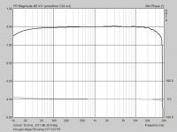
I did some modeling of the circuit today to plan the build using my "universal filter board". Attached is the circuit, FR+phase sim, and noise sim. Gain is set to about 20dB (10x).
I've used a LP filter on the input and in the feedback loop. The MiniDSP (2x4 unbalanced) has an output impedance of 560 ohms according to the spec sheet. This is probably the same for other models, but I am not sure. You can use this to form the LP filter without having to add a series resistance.
I hope to get this built today or tomorrow at the latest. Then I can test it and see if reality and modeling agree.
-Charlie
.
Attachments
Charlie,
Have you considered bypassing the output stages of the MiniDSP boards and taking the output from the expansion port instead. You could build the filters into the buffers and it would allow the use of better quality parts.
For the 2x4 unbalanced the DAC outputs are on pins 1 - 8 and this is the application note passive output stage/filter for the ADAU1701 which is what is on the MiniDSP boards...

And this is the suggested active layout...

Have you considered bypassing the output stages of the MiniDSP boards and taking the output from the expansion port instead. You could build the filters into the buffers and it would allow the use of better quality parts.
For the 2x4 unbalanced the DAC outputs are on pins 1 - 8 and this is the application note passive output stage/filter for the ADAU1701 which is what is on the MiniDSP boards...
And this is the suggested active layout...
I have an Adcom GFA-2535 - though I haven't used it since about 2006; probably should sell the thing... - and I know it doesn't have balanced inputs.
OT I know, but, do you have a price in mind?
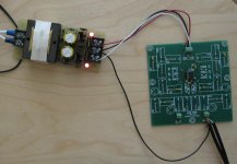
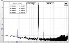
I built the circuit and ran a few tests at a few different frequencies using a dual rail PS that I happened to have out on the desk. This PS is pretty noisy (e.g. 60Hz mains and harmonics are dominant) and uses 7815 and 7915 devices, so I am sure one could do better in that regard. Computer and switching PS for other equipment is located nearby, and this probably inflates the THD+N level but should not influence the THD. I can try to put together another PS that uses 317 and 337 regulators with capacitors on the adjust pins and see if that looks better.
In short it looks like I am getting THD just above 0.001% at 1kHz. The THD level rises slightly to about 0.002% by 5-6kHz or to about 0.006% when the signal level is made to be very high. These numbers aren't bad at all, but probably could be improved if I reduce the feedback resistance.
For comparison, I have seen a THD measurement of the MiniDSP 2x4 itself at about 0.007%:
MiniDSP :: Topic: Re: MiniDSP sound quality test (1/4)
I have not confirmed these measurements, however, the ADAU1701 DSP processing chip used in the MiniDSP products lists -83dB (0.007%) as the THD spec when using the analog inputs, which is exactly in agreement with the measurements in the link above.
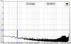
In short, as it stands now the THD from the circuit board is better than the MiniDSP but the noise floor needs to be checked with a better PS or perhaps inside a shielded box/enclosure.
Attached are screen shots taken using REW, one with the 1kHz input signal and the other with no input signal to show PS noise. Also a pic of the circuit board and PS connections out on desktop.
-Charlie
In short it looks like I am getting THD just above 0.001% at 1kHz. The THD level rises slightly to about 0.002% by 5-6kHz or to about 0.006% when the signal level is made to be very high. These numbers aren't bad at all, but probably could be improved if I reduce the feedback resistance.
For comparison, I have seen a THD measurement of the MiniDSP 2x4 itself at about 0.007%:
MiniDSP :: Topic: Re: MiniDSP sound quality test (1/4)
I have not confirmed these measurements, however, the ADAU1701 DSP processing chip used in the MiniDSP products lists -83dB (0.007%) as the THD spec when using the analog inputs, which is exactly in agreement with the measurements in the link above.
In short, as it stands now the THD from the circuit board is better than the MiniDSP but the noise floor needs to be checked with a better PS or perhaps inside a shielded box/enclosure.
Attached are screen shots taken using REW, one with the 1kHz input signal and the other with no input signal to show PS noise. Also a pic of the circuit board and PS connections out on desktop.
-Charlie
Attachments
Last edited:
Ken,
The audio signals on the expansion connector are already downstream of the output filter networks. (They're wired directly in parallel with the RCA jacks.)
Dave.
Thanks Dave. That's a pity and you'd think they'd give you direct access to the DAC outputs. Oh well, just means you'd have to take the outputs on the + side of the output coupling caps (and possibly remove them). I still think it's a worthwhile thing to do.
...and yet more tweaking. I inserted 10R resistors between the shield of the cables leading to and from my measurement system and the circuit board's ground. I've seen this recommended by several prominent authors for reducing shield currents, and it seems to have reduced the noise floor in this case by a couple of additional dB. I went back and checked, and these numbers are getting close to the noise and THD limits of my measurement system.
What remains is a peak at the mains frequency (60Hz) and I would guess that this can be reduced by shielding (e.g. putting the circuit board in a metal enclosure. Comments on this are welcome.
Also of note, the distortion no longer rises above 1kHz, remaining at or below 0.002%. I'd say that this is looking pretty good.
See attached.
.
Attachments
Are these boards still available? How much for 4 channels worth.
Each board can do two channels. If you are interested in getting some of these now, send me a PM.
I am planning to do a revision of the board that will improve grounding and add spots to add an output filter to each channel.
Each board can do two channels. If you are interested in getting some of these now, send me a PM.
I am planning to do a revision of the board that will improve grounding and add spots to add an output filter to each channel.
Awesome, I had totally forgotten about these. I'm staying tuned for the next version, let us know
")
- Status
- This old topic is closed. If you want to reopen this topic, contact a moderator using the "Report Post" button.