I had some time to think about what was happening in the distortion plot shown in the last post, and to re-read the datasheet and consider what is going on in the VCA. This morning I did some more measurements, and made some discoveries.
The VCA essentially works with current. The input of the VCA converts the voltage into a current, which is scaled internally as dictated by the control voltage. The output from the VCA is the scaled current, and it must be connected to a low noise current-to-voltage converter. This is explained in the datasheet and is included in the current board design. The datasheet also mentions that the input voltage spec for all the distortion measurements listed is 0.775Vrms. What level was I using??? I wasn't sure...
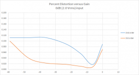
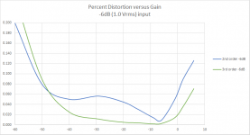
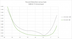
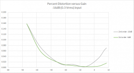
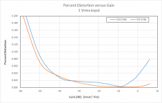
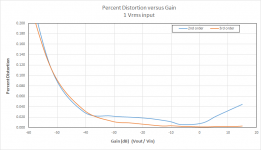
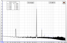
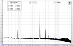
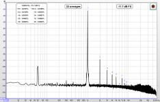
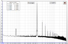
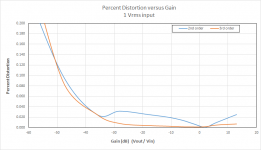
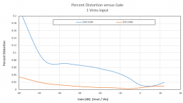
This morning I measured the 0dB level output from my DAC and it was 2Vrms. This means that I have essentially been over driving the VCA input. To test out the theory that I should reduce the input, I re-did the distortion measurements as a function of VCA gain for several input levels. The plots are shown below. Note that the 0dB plot now looks different than the one I provided in the post above. This is because to measure the distortion under gain at 0dB input level I had to REDUCE the input level so that output would not clip the ADC. This resulted in the funny dip in distortion above 0dB gain which is not corrent.
Looking at all the plots you can see some general trends. As the input level is reduced from 0dB (2Vrms) to -16dB (0.3Vrms), the distortion between about -10dB and -40dB of gain is reduced by as much as TEN TIMES. At the same time, the noise floor is starting to come into play below -40dB and this is the reason that the "distortion" levels are increasing at the lowest gains (highest attenuation levels). Also, as the input level is decreased, the minimum in the distortion moves slightly lower in gain level from about -6dB to -10dB or less and the minimum broadens. Lastly, for (positive) gains grater than 0dB, the distortion level is decreased as the input level is decreased. Given all of this info, it seems prudent to try and reduce the input level by at least 9dB or more. This should result in quite low distortion level (e.g. 0.02%) that are very much acceptable for high fidelity reproduction. For the typical listener gain settings between about 0dB and -20dB the distortion remains quite low and only when gain is reduced significantly (e.g. the volume is very low) does the THD+N level creep up.
That brings up to another point: noise. The VCA is biased into class A operation. This provides low distortion figures but increases noise. I have not tested the output using an amp and speaker, but it is possible that the noise level will be noticeable. This depends on the input sensitivity of the amp and the efficiency of the speaker, and the noise generated by the rest of the reproduction chain. The VCA has an adjustable bias current, so I can use less bias to reduce noise but increasing distortion a bit. So it's a balancing game.
How to reduce the input voltage? Since voltage is just converted to current at he VCA input using a resistor I can simply increase the value of the resistor by the ratio of 2/0.775 or about 9dB. I could also the source voltage using an active stage or (for my application) by using the low output level setting on the miniDSP and reducing its internal levels a bit. What we want in the end is less current entering the VCA, so any of these will work. It's just a matter of taking into account the increased noise of each option, so some experimentation might be necessary.
I have to say that I am happy to have uncovered the details explained above, since now it looks possible to get much lower distortion from the VCA volume control. It's just a matter of optimizing all the variable using a little testing and experimentation.
The VCA essentially works with current. The input of the VCA converts the voltage into a current, which is scaled internally as dictated by the control voltage. The output from the VCA is the scaled current, and it must be connected to a low noise current-to-voltage converter. This is explained in the datasheet and is included in the current board design. The datasheet also mentions that the input voltage spec for all the distortion measurements listed is 0.775Vrms. What level was I using??? I wasn't sure...
This morning I measured the 0dB level output from my DAC and it was 2Vrms. This means that I have essentially been over driving the VCA input. To test out the theory that I should reduce the input, I re-did the distortion measurements as a function of VCA gain for several input levels. The plots are shown below. Note that the 0dB plot now looks different than the one I provided in the post above. This is because to measure the distortion under gain at 0dB input level I had to REDUCE the input level so that output would not clip the ADC. This resulted in the funny dip in distortion above 0dB gain which is not corrent.
Looking at all the plots you can see some general trends. As the input level is reduced from 0dB (2Vrms) to -16dB (0.3Vrms), the distortion between about -10dB and -40dB of gain is reduced by as much as TEN TIMES. At the same time, the noise floor is starting to come into play below -40dB and this is the reason that the "distortion" levels are increasing at the lowest gains (highest attenuation levels). Also, as the input level is decreased, the minimum in the distortion moves slightly lower in gain level from about -6dB to -10dB or less and the minimum broadens. Lastly, for (positive) gains grater than 0dB, the distortion level is decreased as the input level is decreased. Given all of this info, it seems prudent to try and reduce the input level by at least 9dB or more. This should result in quite low distortion level (e.g. 0.02%) that are very much acceptable for high fidelity reproduction. For the typical listener gain settings between about 0dB and -20dB the distortion remains quite low and only when gain is reduced significantly (e.g. the volume is very low) does the THD+N level creep up.
That brings up to another point: noise. The VCA is biased into class A operation. This provides low distortion figures but increases noise. I have not tested the output using an amp and speaker, but it is possible that the noise level will be noticeable. This depends on the input sensitivity of the amp and the efficiency of the speaker, and the noise generated by the rest of the reproduction chain. The VCA has an adjustable bias current, so I can use less bias to reduce noise but increasing distortion a bit. So it's a balancing game.
How to reduce the input voltage? Since voltage is just converted to current at he VCA input using a resistor I can simply increase the value of the resistor by the ratio of 2/0.775 or about 9dB. I could also the source voltage using an active stage or (for my application) by using the low output level setting on the miniDSP and reducing its internal levels a bit. What we want in the end is less current entering the VCA, so any of these will work. It's just a matter of taking into account the increased noise of each option, so some experimentation might be necessary.
I have to say that I am happy to have uncovered the details explained above, since now it looks possible to get much lower distortion from the VCA volume control. It's just a matter of optimizing all the variable using a little testing and experimentation.
Attachments
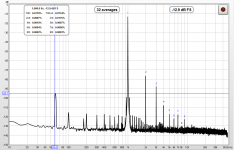
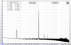
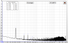
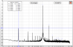
I measured the audio spectrum using REW and a 1kHz input at about -12dB. The distortion spectrum is relatively clean and falls off quickly after 3rd order. Noise is low noise with the AC mains peak at -95dB. Since everything is just lying on the desk next to my computer and I/O lines are not shielded, this is a pretty good result. Looks like noise will not be a major issue.
.
.
Attachments
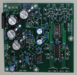
Final VCA based volume control board for miniDSP crossovers
After some more tweaks I think I have arrived at the final component values.
The plot below shows what I expect (because I just measured it) in terms of real world performance from the circuit. I made a couple adjustments in the resistor values for input and output, and limited the input voltage to 1Vrms (the lower gain setting on the miniDSP boards).
This is now looking pretty good. Distortion in the critical gain range from -40dB to 0dB is less than 0.04%, and below 0.02% between -30dB and -10dB. Noise and hum seem to be low enough to be of no concern.
The gain in dB is directly proportional to the control voltage. Control of the volume can be done using either a linear potentiometer connected to the onboard 5V power, or using an external 0-5V signal e.g. from a PIC or other circuitry. This gives the user some options for implementing the volume control.
Because it uses all thru-hole components, the board is easy to assemble. I am thinking about redesigning the board to include a +/- 15Vdc and +5V power supply that can also be used to power external circuit boards if so desired. Unfortunately the components (ICs) used in this circuit are rather expensive: in single quantities they total about $16, with the rest of the components adding up to another $20 or so, plus a few more $$ for the power supply components that I want to add.
Attachments
One more tweak...
I came up with one more idea to try, and the result seems to be an improvement - the distortion remains low even when gain begins to be positive, as high as +15dB in this example (that's a lot). Since this is where things are the "loudest" its probably a good idea to keep distortion low there, and as a tradeoff let the distortion rise a little more below -40dB gain. That's what has been accomplished here. Less distortion where you will notice it most. Distortion plot attached.
.
Attachments
And finally...
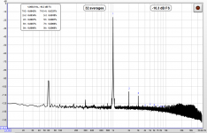
I was a little concerned about the nose level, so I moved the bias from full class A mode slightly towards class AB mode. This did change the distortion curve slightly, but the reduction in noise was real so I am happy with this change. See plot below.
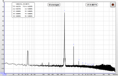
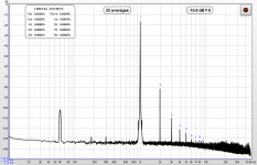
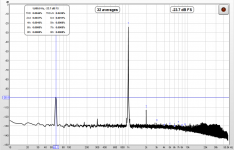
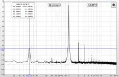
Then I decided to do a few spectrum measurements using REW to probe how the distortion profile and noise change with input and gain. I looked at 0dB, -10dB, and +10dB VCA gain at a variety of input signal levels. I also turned the gain all the way "down" and muted the input to check the noise floor. See plots below. All of these look pretty good, actually better than I had been expecting from the ARTA distortion measurements. Under all conditions the distortion remains low and noise is not an issue. Mains AC frequency (60Hz) is around -95dB or less.
I have also been doing some listening tests using headphones. This was one reason that I decided to change the bias - in between tracks I could hear the noise floor (like white noise) when VCA gain was at 0dB or higher. This is now less of a problem, although still there at the highest gains. I will just have to live with it. At lower gains the noise vanishes, so I am not too concerned. All in all, this seems to be a very usable volume control and with this component completed I can move on to the next thing in the project.
With this setup, I have plenty of output voltage on tap (over 4 Vrms) and very good gain/volume control.
NOTE: some plots are found in the next post.
I was a little concerned about the nose level, so I moved the bias from full class A mode slightly towards class AB mode. This did change the distortion curve slightly, but the reduction in noise was real so I am happy with this change. See plot below.
Then I decided to do a few spectrum measurements using REW to probe how the distortion profile and noise change with input and gain. I looked at 0dB, -10dB, and +10dB VCA gain at a variety of input signal levels. I also turned the gain all the way "down" and muted the input to check the noise floor. See plots below. All of these look pretty good, actually better than I had been expecting from the ARTA distortion measurements. Under all conditions the distortion remains low and noise is not an issue. Mains AC frequency (60Hz) is around -95dB or less.
I have also been doing some listening tests using headphones. This was one reason that I decided to change the bias - in between tracks I could hear the noise floor (like white noise) when VCA gain was at 0dB or higher. This is now less of a problem, although still there at the highest gains. I will just have to live with it. At lower gains the noise vanishes, so I am not too concerned. All in all, this seems to be a very usable volume control and with this component completed I can move on to the next thing in the project.
With this setup, I have plenty of output voltage on tap (over 4 Vrms) and very good gain/volume control.
NOTE: some plots are found in the next post.
Attachments
-
 -10dB gain -24dB input level.PNG73.4 KB · Views: 68
 -
 -10dB gain -18dB input level.PNG73.5 KB · Views: 61
 -
 -10dB gain -12dB input level.PNG73.1 KB · Views: 56
 -
 -10dB gain -6dB input level.PNG73.1 KB · Views: 64
 -
 0dB gain -24dB input level.PNG71.9 KB · Views: 65
 -
 0dB gain -18dB input level.PNG73.2 KB · Views: 73
 -
 0dB gain -12dB input level.PNG74.2 KB · Views: 64
 -
 0dB gain -6dB input level.PNG75.6 KB · Views: 72
 -
 distortion versus gain at -6dB input level with modified bias.png21 KB · Views: 77
After making a few tweaks to my "rev A" board for the volume control I decided it was time to redesign the layout. Since there was room on the board, I decided to include an on-board power supply. I've managed to implement regulated +/-15V as well as a 5V supply for the volume control. I also put both the TO-92 and TO-220 packages on the board for the +/-15V supplies. I included a "DC POWER" input/output connector to allow for several powering options. (A) I can install the TO-220 packages in the PS and use the supply to power other boards using the DC POWER as an output. (B) I can populate the board with the TO-92 parts if no external power delivery is needed. (C) if I instead want to use external power supplies, I can supply DC power to the board via the DC POWER connector and omit the rectifier and large caps. So, it's very versatile in terms of how you can power it, and use it to power other boards.
I added a couple of things that should help the circuit perform better, and the VCA section has been consolidated. I have tried to be careful with grounding using a star topology. I will do some error checking and then send this out to the fab in a couple of days.
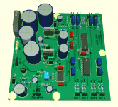
Here is what the populated "rev B" board should look like.
.
I added a couple of things that should help the circuit perform better, and the VCA section has been consolidated. I have tried to be careful with grounding using a star topology. I will do some error checking and then send this out to the fab in a couple of days.
Here is what the populated "rev B" board should look like.
.
Attachments
Last edited:
Update...
While I am waiting, waiting, waiting for the new PCB to arrive I am building the speaker that I will be using with this system. It's a 3-way open baffle/nude system that I hope (barring any unfortunate events) to demo at the NorCal DIY Audio group meeting at the end of this month. I want to integrate the electronics into the speaker including amplification and I have all of it functioning, the problem is where to put it all... I finally decided that I will create a rectangular "plinth" base that the speaker will rest on, and that will contain all the electronics. There are definitely a lot of things left to do!
While I am waiting, waiting, waiting for the new PCB to arrive I am building the speaker that I will be using with this system. It's a 3-way open baffle/nude system that I hope (barring any unfortunate events) to demo at the NorCal DIY Audio group meeting at the end of this month. I want to integrate the electronics into the speaker including amplification and I have all of it functioning, the problem is where to put it all... I finally decided that I will create a rectangular "plinth" base that the speaker will rest on, and that will contain all the electronics. There are definitely a lot of things left to do!
I finally have the speakers more or less done and I think that they look quite nice. Now I need to turn my attention back to the electronics to get everything set up properly for a DIY event next weekend.
There is a separate writeup of the speaker in the MultiWay forum, including a picture, at this link:
http://www.diyaudio.com/forums/multi-way/263597-mid-size-open-baffle-plus-fin-design-prototype.html
There is a separate writeup of the speaker in the MultiWay forum, including a picture, at this link:
http://www.diyaudio.com/forums/multi-way/263597-mid-size-open-baffle-plus-fin-design-prototype.html
I finally had some time to build a test one of the new revisions to the 4-channel VCA board that includes on-board power supply. This was a little more challenging because I bought a batch of components and one of the values that was supposed to be 82k Ohm included about 10% of 220 Ohm parts and some of these were used in the build... not good. Luckily this was not too difficult to fix once I figured out just what and where the problems were. And to think that I got these parts was from the well-known seller M*u$er. Eek.
But now that it's working... voila: 4-channel gain/volume control with 15dB gain and sufficiently low distortion to use after my MiniDSP crossovers. Just add a 15-0-15 transformer and you are good to go.
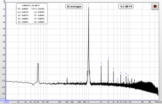
Distortion peaks at about 0.04%, less at lower input signal level, and is dominated by second order.
The mains-related components are low. 60Hz is at about -90dB and harmonics are about 10dB below that.
I've attached a representative distortion spectra driven with a 1kHz input.
But now that it's working... voila: 4-channel gain/volume control with 15dB gain and sufficiently low distortion to use after my MiniDSP crossovers. Just add a 15-0-15 transformer and you are good to go.
Distortion peaks at about 0.04%, less at lower input signal level, and is dominated by second order.
The mains-related components are low. 60Hz is at about -90dB and harmonics are about 10dB below that.
I've attached a representative distortion spectra driven with a 1kHz input.
Attachments
And even more "challenges" have been overcome... some of the VCA ICs that I had (probably from an Ebay auction I won a few years ago) were DUDs. Took me a little while to figure out just what what going on... I've now ordered up a batch of "genuine" new parts that I can use on future boards and development.
I'm very happy to finally have a working pair of boards. The PAIR is key, since I need to put one in each speaker along with the electronics that I built.
I'm very happy to finally have a working pair of boards. The PAIR is key, since I need to put one in each speaker along with the electronics that I built.
I spent some time to "listening" to the new boards. I noticed that the noise floor is reduced compared to the previous version, especially at gains above 0dB. At +15dB (max gain) there is hardly any noise thru my headphones. This is probably a combination of the board's improved layout, the on-board PS, and a bias that was moved slightly towards class AB from class A.
Unfortunately, because of a really strange error that I did not catch while I was I doing the layout, one ground track was not routed properly (at all!). Luckily I was able to save the board by using a wire to connect to a nearby ground thru-hole, but since I need to fix this I'm currently working on one more revision.
The next revision will also include a few tweaks that should make the board even better, and provide a little more flexibility. Stay tuned...
I made a couple of quick measurements. Attached is:
12dB gain is 4x voltage gain. You can set the minidSP board for 0.9Vrms output and get almost 4Vrms out of the VCA board at low distortion. That should be able to drive just about any amplifier out there past its rated input sensitivity (e.g. you get some analog domain headroom!).
- spectrum taken at 0dB gain
- distortion versus gain from -60dB to +12dB
12dB gain is 4x voltage gain. You can set the minidSP board for 0.9Vrms output and get almost 4Vrms out of the VCA board at low distortion. That should be able to drive just about any amplifier out there past its rated input sensitivity (e.g. you get some analog domain headroom!).
Attachments
Last edited:
Just a quick update on the 4-channel VAC volume control... I made one more version of the board that allows me to adjust various settings, either things that needed to be fined tuned (to get exactly 5Vdc from the regulator for instance) and I have it in hand but am tied up with some other stuff for the next week or so. I plan to built and test the board, and then do some experimentation. For instance, I can tweak the bias setting with a pot. I think that it will be interesting to see how the distortion profile and noise change as I change the bias. Hopefully this will allow me to squeeze a little more performance out of the IC.
The system is working - I demoed it at a recent DIY using the wireless spdif link but without the remote volume control or VCA board so I wan't able to add gain. As a result I suffered from the same old problem - I had to overdrive the miniDSP and as a result the output was distorted. Solutions for this are coming!
The system is working - I demoed it at a recent DIY using the wireless spdif link but without the remote volume control or VCA board so I wan't able to add gain. As a result I suffered from the same old problem - I had to overdrive the miniDSP and as a result the output was distorted. Solutions for this are coming!
So, these ones have gain and will work with a 15-0-15 transformer? I think I might have to have a pair of these")
I'd be willing to send you a pair of the PCBs for the "rev B" version but I don't have a BOM worked up for it yet. Keep in mind each board has its own PS and transformer, if you follow the design, but there is a way to connect boards together to share power if you want to try that. Drop me a PM about it if you are interested.
I'm still chipping away at this project. It has been stalled for awhile because I was the RF connection I put together was not reliable. It seems that the transmitter was broadcasting a very noisy signal - I've replaced it with an updated version of the unit that seems to be much better. Where before there were dropouts and ticks and pops as the spdif lost synch or data, now there is just a nice clean stream (at least based on my listening tests over the past couple of days).
With the RF link in better shape, I hope to begin working with the new VCA board soon, and have some plans for changes to the control system as well. I'll post new info when I have it.
With the RF link in better shape, I hope to begin working with the new VCA board soon, and have some plans for changes to the control system as well. I'll post new info when I have it.
- Status
- This old topic is closed. If you want to reopen this topic, contact a moderator using the "Report Post" button.