Hello,
Here is a little update and thanks for your patience.
Our team compiled a new set of plug-ins with a new DSP structure allowing us to fix that metering bug. We also figured out a way to not "break" the configuration you may have had in the past. That's why it took us a bit of time to release all this to you..")
Note that this issue only appeared on the miniDSP 2x4 based platforms (balanced/unbalanced).The 8x8, 2x8, 4x10, 10x10, nanoDIGI, miniSHARC, OpenDRC are all using a different metering that didn't that bug.
If you log-in to your user downloads section, you should have access to the Beta version.
IMPORTANT NOTE: Please take the time to read the "README" file that was included as part of the ZIP file. It does recommend to perform a backup of your old configuration first.
Hoping this info helps.
DevTeam
Here is a little update and thanks for your patience.
Our team compiled a new set of plug-ins with a new DSP structure allowing us to fix that metering bug. We also figured out a way to not "break" the configuration you may have had in the past. That's why it took us a bit of time to release all this to you..
Note that this issue only appeared on the miniDSP 2x4 based platforms (balanced/unbalanced).The 8x8, 2x8, 4x10, 10x10, nanoDIGI, miniSHARC, OpenDRC are all using a different metering that didn't that bug.
If you log-in to your user downloads section, you should have access to the Beta version.
IMPORTANT NOTE: Please take the time to read the "README" file that was included as part of the ZIP file. It does recommend to perform a backup of your old configuration first.
Hoping this info helps.
DevTeam
Report on using Beta version A. Behaviour of plug-ins ref. PC operating system
Report on using Beta version
MiniDSP 2 Way advanced Plug-in Version v1.09 (Release date 12/3/2013)
MiniDSP 4 Way advanced Plug-in Version v1.08 (Release date 12/3/2013)
A. Behaviour of plug-ins ref. PC operating system
See attachment for details.
The problem is that the beta version does not load old configuration .xml files.
I used an .xml editor e.g.
Download XML Notepad 2007 from Official Microsoft Download Center to read my old .xmls and copy the settings into .xml created with the beta version.
George
Attachments
B. Attenuation slider steps. C. RMS Meter reading with sinusoidal signal
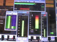
B. Attenuation slider steps.
Each step of the input (and output) attenuation slider is 0.4db all along down to the maximum attenuation of –70db.
There are two numerical indicators for the applied attenuation in db.
One is just above the mute button always visible. This is the correct attenuation reading.
The other appears when we click with the screen pointer over the slider. This comes inside a blue frame and it’s indication is a bit in error, on some steps it read 0.1db below the actual attenuation.
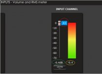
C. RMS Meter reading with sinusoidal signal
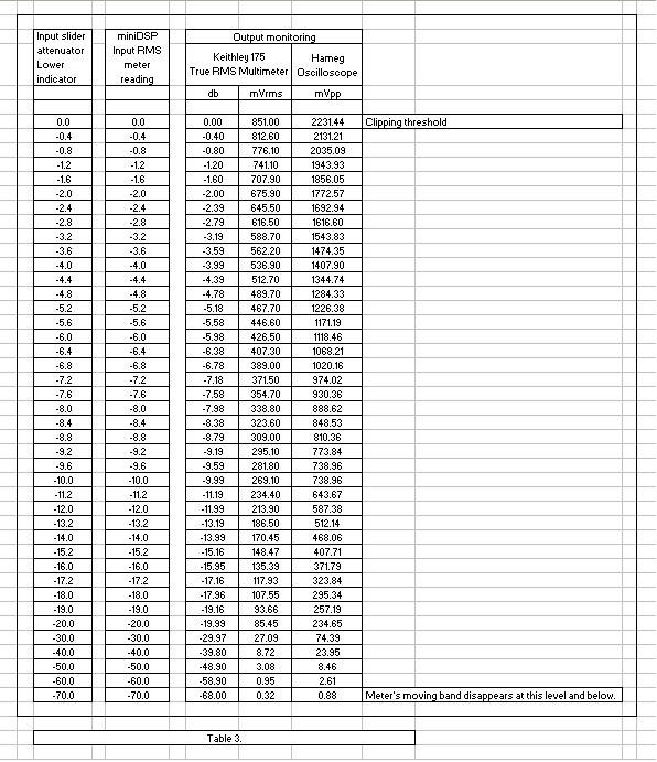
Input and output RMS meters read correctly in db, following the voltage law [ db=20*LOG (V/Vref) ]
The Vref is the 0db of the meter which correctly represents the maximum signal before clipping.
For 2V boards:
0db at input meter corresponds to 2.173Vrms analogue input sinusoidal signal.
0db at output meter corresponds to 0.851Vrms analogue output sinusoidal signal.
For 0.9V boards:
0db at input meter corresponds to 0.981Vrms analogue input sinusoidal signal.
0db at output meter corresponds to 0.851Vrms analogue output sinusoidal signal.
Now, the top of the moving band can be used as a visual level indicator as it fluctuates close to the attenuator’s db scale.
Meter’s moving band disappears below –70db signal level.
For precise signal amplitude monitoring, the numerical signal level in db appears below the meters moving band (resolution 0.1db).
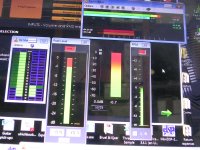
The output meter correctly registers the signal level reaching the output, that is, it is affected by any attenuation setting at the input and any boosting by the filters.
As long as the cumulative boosting by the filters in any specific frequency band do not exceed 24db, the output meter reading below 0db can be reliably taken as an indication for undistorted analogue output signal, that is unclipped and unskewed signal.
If boosting in any specific frequency band exceeds 24db, signal waveform will be skewed and this distortion does not reflect in the amplitude, thus output meter may continue to show negative db numbers. The logic is a bit complex and I will explain if you want, but always remember not to exceed this 24db cumulative boosting.
George
B. Attenuation slider steps.
Each step of the input (and output) attenuation slider is 0.4db all along down to the maximum attenuation of –70db.
There are two numerical indicators for the applied attenuation in db.
One is just above the mute button always visible. This is the correct attenuation reading.
The other appears when we click with the screen pointer over the slider. This comes inside a blue frame and it’s indication is a bit in error, on some steps it read 0.1db below the actual attenuation.
C. RMS Meter reading with sinusoidal signal
Input and output RMS meters read correctly in db, following the voltage law [ db=20*LOG (V/Vref) ]
The Vref is the 0db of the meter which correctly represents the maximum signal before clipping.
For 2V boards:
0db at input meter corresponds to 2.173Vrms analogue input sinusoidal signal.
0db at output meter corresponds to 0.851Vrms analogue output sinusoidal signal.
For 0.9V boards:
0db at input meter corresponds to 0.981Vrms analogue input sinusoidal signal.
0db at output meter corresponds to 0.851Vrms analogue output sinusoidal signal.
Now, the top of the moving band can be used as a visual level indicator as it fluctuates close to the attenuator’s db scale.
Meter’s moving band disappears below –70db signal level.
For precise signal amplitude monitoring, the numerical signal level in db appears below the meters moving band (resolution 0.1db).
The output meter correctly registers the signal level reaching the output, that is, it is affected by any attenuation setting at the input and any boosting by the filters.
As long as the cumulative boosting by the filters in any specific frequency band do not exceed 24db, the output meter reading below 0db can be reliably taken as an indication for undistorted analogue output signal, that is unclipped and unskewed signal.
If boosting in any specific frequency band exceeds 24db, signal waveform will be skewed and this distortion does not reflect in the amplitude, thus output meter may continue to show negative db numbers. The logic is a bit complex and I will explain if you want, but always remember not to exceed this 24db cumulative boosting.
George
Attachments

Last edited:
D. RMS Meter reading with dynamic music signal.
D. RMS Meter reading with dynamic music signal.
I find the RMS meters in this version to respond somewhat faster to dynamic signals than the meters in the previous version. But still, they do not have the ballistics of a peak meter.
A led indicator showing instantaneous peaks exceeding 0db (with holding time 1 sec) is still in need.
I spent some hours watching in real time and playing back pc screen video recordings, comparing behavior of miniDSP RMS meter to VU meter, peak meter, PPM and bit depth meter.
In case you don’t have a signal generator to set the 0db level and you don’t know the maximum output of your source, I would suggest:
For heavily compressed music, the input meter not to exceed –3db level (3db headroom). These recordings are close to 0db most of the time and have encoded already clipped material (good stuff actually for setting zero level if you don’t have a signal generator).
For relative uncompressed light music, the input meter not to exceed –12db level (12db headroom).
For good recordings (jazz, classic and opera fall in this category), the input meter not to exceed –22db level (22db headroom).
For live unprocessed takes, the input meter not to exceed –30db level (30db headroom).
George
Attachments
Last edited:
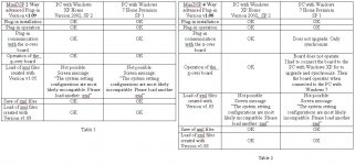
Doing the output measurements shown in Table 3 http://www.diyaudio.com/forums/attachments/minidsp/336300d1363385323-signal-level-minidsp-x-over-meter-attenuator-readings.jpg
I have to add two issues which are related to hardware, not to software.
1. The output noise of the miniDSP 2x4 board (Input shorted, open or with 50R across and no signal applied. Output loaded with 10k,) is 15mVpp 2MHz and harmonics.
2. Switch-off thumb:-200mV. Switch-on thumb: +2mV.
Duration of these thumbs depend on the capacitance of the psu that feeds the board.
Switch-off thumb is large and considering the gain of an amplifier connected to the output of the board, is a bad story for speakers. Always turn off amplifiers first, wait some tens of seconds and then turn off miniDSP board.
George
Member
Joined 2009
Composing the gain structure correctly on the miniDSP was indeed the hardest part of setting it up. Everything else was straight forward and intuitive. I did not realize that my input signal was clipping for some time until forum members repeatedly suggested that I it probably was.
I think a Gain Structure section with a simple step-by-step guide should be included in the manual. It should describe how to check your gain structure with a software signal generator or a wave file that can burned on a CD.
A very helpful addition to the software will be a clipping indicator. Fixing the peak meters will be fine but I think it will be great if there is an additional way to show an error when the system clips.
I lower the input level by the highest amount of gain I add later with filters. It was pointed out earlier that the numbers on the input level are not dB so my gain structure could still be wrong. I suspect that not a lot of people who use miniDSP know to do that. Some open baffle designs call for filters that add 40dB and more. I doubt that many people understand you can't really do this with DSP.
Is this file still available?
Only file showing in my User Downloads section is a "miniDSP Xover 2way PEQ" dated 02/08/2011
It is still in my User downloads section.
Composing the gain structure correctly on the miniDSP was indeed the hardest part of setting it up. Everything else was straight forward and intuitive. I did not realize that my input signal was clipping for some time until forum members repeatedly suggested that I it probably was.
I think a Gain Structure section with a simple step-by-step guide should be included in the manual. It should describe how to check your gain structure with a software signal generator or a wave file that can burned on a CD.
A very helpful addition to the software will be a clipping indicator. Fixing the peak meters will be fine but I think it will be great if there is an additional way to show an error when the system clips.
Boris I agree to what you say. Do you have some questions as to how you can test the gain structure within miniDSP board?
I lower the input level by the highest amount of gain I add later with filters. It was pointed out earlier that the numbers on the input level are not dB so my gain structure could still be wrong. I suspect that not a lot of people who use miniDSP know to do that. Some open baffle designs call for filters that add 40dB and more. I doubt that many people understand you can't really do this with DSP.
Input and output attenuators were always in db, as well as filters gain.
The meters were not.
With this beta version, everything is in db. Nice and correct.
If one is adding up to 24 db total boost in a specific freq range, he does not need to lower input level.
He can attenuate at the specific output where the boosted frequencies are rooted.
E.g.
Boosting 24db total at 50Hz.
Apply attenuation at LF output of 24db. No input attenuation required.
Of course you can apply this attenuation only at the input, but then you will attenuate the HF as well.
You can split the attenuation as you please, 2db at input, 22 at output if this serve your setting better.
Total attenuation will have to be of equal amount to boosting.
When exceeding this 24db boost, one has to apply attenuation at the input too.
E.g.
Boosting 40db total at 50Hz.
Apply attenuation at LF output of 24db. Required attenuation at input of 16db (16=40-24).
Of course you can apply 40db attenuation only at the input, but then you will attenuate the HF as well.
Again, you can split the attenuation, 20db at input, 20 at output if you like.
But do not apply 2db at input and 38 at output. You’ll have skewed output.
For ensuring skew free output, output attenuation shall be limited to 24db max.
The rest of the attenuation has to be applied at the input.This attenuation in db should be equal to total filter boosting in db minus 24db.
All this may be correct or false, depending if one has checked first the max voltage of the signal applied at the input of the mimiDSP board. This is the first and most important step for gain planning.
George
Last edited:
Member
Joined 2009
I see now, I had the wrong idea. Thank you, George for the detailed explanation!
I only have basic understanding of DSP, I'm sorry if I confuse anyone by posting my wrong assumptions.
I understand that attenuating the input level will decrease the resolution of the system since signal will initially be converted using less bits. At an input level of 0 the conversion will use 24bits, at -6dB 23bits, at -12dB 22bits and so on.
I understand now that keeping the input at 0 and lowering the output level instead can keep the digital resolution of the system at 24bits.
Last edited:
Ahh, kind of.....
The word 'resolution' is kind of meaningless in a correctly dithered quantizer, as it has a noise floor, but is linear and does not abruptly go silent at 1LSB (Thanks to the dither). Any quantizer that is not correctly dithered is just plain broken.
As you turn the input down, the output gets closer to the noise floor, just the same as happens in an analogue system, the word length sets the dynamic range, but a narrow tone can be heard down well into the 20-20K noise floor if the conversion is done right.
Dither (Like the necessity of reconstruction filtering) is generally poorly understood among audio types and silly diagrams of stairstep waveforms give rise to many myths.
Here is an undithered piano at 3 bits, sounds like **** does it not?
http://media.soundonsound.com/sos/feb08/audio/digitalaudio/piano_3.mp3
Note that the thing is silent when there is no signal, but sounds NASTY and that the decay on the notes mutes abruptly as the signal drops below the smallest quantisation threshold. This is the only one to which a notion of 'resolution' can be applied, because it is funamentally broken (No dither).
Here is the same thing with TPD dither applied before quantisation (still at 3 bits).
http://media.soundonsound.com/sos/feb08/audio/digitalaudio/dithered_piano_3.mp3
It hisses all the time at roughly 1 LSB, but now the notes decay smoothly down into the noise floor.
Finally, here is the same thing but with some fairly crude noise shaping applied to the dither noise, http://media.soundonsound.com/sos/feb08/audio/digitalaudio/noiseshaped_piano_3.mp3, still hissy, but far better.
Regards, Dan.
I see now, I
Boris, no need to worry. We are all on the same boat. If we knew a lot on DSP, we would build and program our own creations
.Both input and output attenuations work in the digital domain.
Attenuating at the input will lower the resolution on the signal going to all the outputs.
Attenuating at the output will lower the resolution on the signal going to this output only.
But as Dan explained, it is not a very big issue, at least compared to distortion from digital overdriving (clipping or skewing distortion) which we try to avoid by attenuating the signal.
George
Ahh, no it will NOT lower the resolution, at least not if it is done correctly, what it will do is push the signal closer to the noise floor in exactly the same way as attenuating a analogue signal will.
Digital audio is somewhat couterintuitive that way, and notions like resolution borrowed from massively subsampled imaging systems do not apply in any meainingful way.
Digital clipping is of course wince inducingly nasty (Mostly because of aliasing), but with reasonable design and sane headroom margins should never be an issue.
Regards, Dan.
It is still in my User downloads section.
George
Edit: And then he sees the PM.
Last edited:
Ahh, no
Regards, Dan.
I agree Dan. There is a lot of posting regarding attenuation in analogue vs digital domain in this site. No need to do it again in this thread.
Michael has done a good job on gain structure here:
http://www.diyaudio.com/forums/showthread.php?t=186018
George
Member
Joined 2009
Hoping this info helps
Thanks Devteam and George!!
After dealing with the gain through miniDSP x-over board with the beta version of the 2x and 4x plug-in, I had to look at the gain of the miniAmp
miniAMP | miniDSP
This board is very handy during the experimentation phase.
As with the x-overs I had to check the gain of the miniAmp for to see the signal level up to overload.
Jumpers allow for –3db, +3db, +9db and +12db gain setting. They refer to I2S input signal level, so I had to find out what these numbers mean.
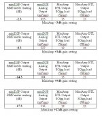
Feeding the input of the stacked miniDSP x-over with the 1281Hz sinusoid as before and having the settings flat, I was monitoring the analog output (10kOhm load) and the speaker output of the miniAmp (8Ohm load).
Below is the max levels as shown by the output RMS meters of the miniDSP x-over for max undistorted output of the miniAmp.
George
miniAMP | miniDSP
This board is very handy during the experimentation phase.
As with the x-overs I had to check the gain of the miniAmp for to see the signal level up to overload.
Jumpers allow for –3db, +3db, +9db and +12db gain setting. They refer to I2S input signal level, so I had to find out what these numbers mean.
Feeding the input of the stacked miniDSP x-over with the 1281Hz sinusoid as before and having the settings flat, I was monitoring the analog output (10kOhm load) and the speaker output of the miniAmp (8Ohm load).
Below is the max levels as shown by the output RMS meters of the miniDSP x-over for max undistorted output of the miniAmp.
George
Attachments
- Status
- This old topic is closed. If you want to reopen this topic, contact a moderator using the "Report Post" button.