I was playing around with my 8x8 after the Redskins game today, and accidentally unplugged it. MASSIVE turn off noise. I had my amp set to turn on via the miniDSP's rem-out, but the remote jumper was untouched and the rem-in was not used.
The amp it was connected to (ElectroVoice CPS-8.5) has a rated voltage swing of 63V into 4Ω...and now I've officially blown my first driver that wasn't a Jordan Module or JX53. Fortunately, it was a cheap car audio speaker, and not the big, expensive Aurasound woofers or the irreplaceable JBL SUB1500s. But it has a phase plug, and the resulting surge literally changed the rest position of the cone back about 2-3mm.
Does the 8x8 still thump like that with remote-in/remote-out? I don't currently have a driver I don't care about to test, but if so then I and anyone else using these things really needs to consider keeping it on and connected to a UPS.
I am currently trying to make a relay setup for my 8x8 that mutes instantly on power down, and has a delayed mute on power up. I think this approach is the only real solution in case of "brown out".
I haven't used rem in/out but i don't see how it can help if the power is removed.
I haven't used rem in/out but i don't see how it can help if the power is removed.
I am currently trying to make a relay setup for my 8x8 that mutes instantly on power down, and has a delayed mute on power up. I think this approach is the only real solution in case of "brown out".
I haven't used rem in/out but i don't see how it can help if the power is removed.
One way that I have thought of to address both power down and power up is the following concept:
Use TWO relays:
- Relay 1 is connected between the amplifier output and the speaker. It should be a 10+ amp 240VAC contact, 120VAC coil. The coil is powered via Relay 2:
- Relay 2 is a 120V contact (current rating is low), 12VDC coil.
Relay 1 is controlled by a timer (such as a type 555/556) to provide turn-on delay of a few seconds. This provides delay-on protection for the speaker.
As soon as AC mains power is disconnected (within 7-8 msec), relay 2 will open and the speaker will be disconnected. This should be fast enough to protect the speaker from "pop" transients coming from line-level components like the MiniDSP shutting down while the amplifier is still powered up.
If someone will produce a PCB or populated PCB following this concept, I am willing to buy!!! Otherwise, this is not too hard to make using point-to-point wiring.
-Charlie
Last edited:
That is precisely what i am building, except i am using some 12 VDC relays for "Relay 2" and activate them with a rectified but unsmoothed DC supply for fast decay at power down.
Didn't realise i could go for relays with mains voltage coils - that is interesting and would make it a bit simpler.
For the 555 i am using a circuit from here
under "Power ON Delay Circuits" circuits number 2 or 3
Didn't realise i could go for relays with mains voltage coils - that is interesting and would make it a bit simpler.
For the 555 i am using a circuit from here
under "Power ON Delay Circuits" circuits number 2 or 3
One way that I have thought of to address both power down and power up is the following concept:
Use TWO relays:
The mains AC "live" is connected first to the Relay 2 contact, and then to coil of Relay 1. This provides two ways to turn off/on the speaker: relay 1 or the mains AC.
- Relay 1 is connected between the amplifier output and the speaker. It should be a 10+ amp 240VAC contact, 120VAC coil. The coil is powered via Relay 2:
- Relay 2 is a 120V contact (current rating is low), 12VDC coil.
Relay 1 is controlled by a timer (such as a type 555/556) to provide turn-on delay of a few seconds. This provides delay-on protection for the speaker.
As soon as AC mains power is disconnected (within 7-8 msec), relay 2 will open and the speaker will be disconnected. This should be fast enough to protect the speaker from "pop" transients coming from line-level components like the MiniDSP shutting down while the amplifier is still powered up.
If someone will produce a PCB or populated PCB following this concept, I am willing to buy!!! Otherwise, this is not too hard to make using point-to-point wiring.
-Charlie
But I'm not sure why the first relay is needed, unless one doesn't have a 12V trigger on one's preamp. The miniDSP's existing rem-out already delays things by a little bit. I've not experienced turn-ON thump when using the rem-out with my amps (Sherwood A-965 for mains, ElectroVoice CPS-8.5 for multisubs).
The second relay, in light of my recent experience, seems very useful.
DIY electronics design is beyond my abilities. Is something like relay 2 alone available in a plug-and-play product?
I think in Charlie's explanation of his proposed design Relays 1 and 2 may have been mixed up at some point. Anyway the circuit in theory should solve all the issues with turn-on and turn-off thump in all scenarios, where REM in/out alone might not.
You have one relay which is activated with a delay timer and switches the coil of a second relay(s) which switches the audio signal(s) to speaker/line level.
I guess you could use REM out to activate this primary relay with a delay - around 2 seconds according to minidsp datasheet. REM out provides just 10 mA at 12V so it might need to drive a transistor, which then drives the primary relay.
All is fine until power is removed - either to the miniDSP alone or everything due to a power cut. My question is how quickly does rem out decay? The miniDSP will turn off (producing a thump), REM out with drop to 0V immediately triggering the amplifier to turn off. But whether the amps are shut down quickly enough to suppress the thump through the speakers has to be tested.
In charlie's design the use of mains to power to the secondary relays means they will deactivate immediately in all cases where the minidsp loses power. No matter what happens with the amps, the thump isn't getting to them. That makes me feel a lot happier!
I am building this circuit with 24 VAC secondary relays which will decay as fast as the mains but without having mains everywhere in the box.
Because your amps have trigger inputs i would give the REM in/out feature a thorough testing with a full range speaker that can handle the thumps - that alone could be enough to solve the problem.
Last edited:
Because your amps have trigger inputs i would give the REM in/out feature a thorough testing with a full range speaker that can handle the thumps - that alone could be enough to solve the problem.
That's the plan right now.
I think I have a little subwoofer (Gallo Nucleus Micro, small closed box with Peerless DVC 8" woofer) that I don't really care if it blows up. Just need to go to my storage cellar and get it.
My hope is that the end-effect of this thread is simply a caution not to use the remote-out trigger without using the remote-in trigger as well. Another alternative is to consider a small UPS on the miniDSP not optional.
Hi,
The turn off bump is a significant problem with MiniDSP.
I have tried two methods , and both of these seem to work well:
1) Use speaker protector IC to short the outputs of MiniDSP when power is removed. This is perhaps the best solution overall although another board is need. I have tried it with uPC 1237 and it worked well. But its a bit mess when many outputs must be shorted and many relays have to be used.
2) Use large enough supply capacitors so MiniDSP is shut down after power amplifier does. Only useful when miniDSP is used in the same chasis as power amp. In my case it was 10,000 uF
Hope this helps.
Regards,
Lukas.
Last edited:
I just posted a question about this power down transient today at the MiniDSP forum. Maybe it's important to note that the transient is only severe when the AC power cord is unplugged from the power supply, not when unplugging the DC cable. It's not just a matter of the power disappearing from MiniDSP's perspective. Is it possible a different power supply would solve the problem?
As for your question of Pop when unplugging the DSP, you're talking of a lot inputs/outputs op amps + DSP drawing a lot of current. In other words, if you un-plug the AC (without REM in/out) the storage cap on board (3300uF) may not be enough to hold the power long enough to allow the microcontroller to mute the output.
A couple of solutions:
- Add a larger storage cap.. We'd need to investigate that on our side.
<snip>
MiniDSP say the above over on their own forum.
I have the 8x8 board in a box from MiniDSP ... Does anyone know if the bove solution would still be possible for me? (It sounds like the best approach).
Hi,
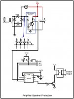
Here it is a suggestion on how to prevent the speaker output "thump" when the power it is turn off by using the Basic micro NANO 8. Attached it is a schematic how to do it. I will try to explain how it is works but I am not a technical writer. I Know that when you speak about using a micro that it is the end of the discussion but it is not big science programming the NANO 8 using basic instructions.
Here it is description how it work.
The purpose of the micro it is to read the zero crossing pulses every time that the AC cross the base line as shown in the schematic. It will produce a pulse that the micro will read and will keep monitoring it until one of the pulse failed. If one of the pulse failed means that there it is a problem with the AC power and the micro will immediately open the output relay preventing the "thump" in the speaker. Also at the powered up can be programmable to delay the close of the output relay to allow the settling of the PS voltages. It is a simple circuit and can be done easily using common components. The micro NANO 8 cost only 2.99 and the all project will run under $ 30 dollars.
If interesting I will write the program to show how easy it. I call the NANO8 the programmable LM555 with 4 individually programmable outputs and only cost $2.99.
Attachments
Maybe it's important to note that the transient is only severe when the AC power cord is unplugged from the power supply
Hmm.... the thump for me is also very severe when disconnecting the DC plug form the miniDSP. (Haven't tried disconnecting from the AC side)
I'm using the power adapter supplied with the MiniDSP 8x8 "in a box" (4x10 HD)
Here it is a suggestion
Thanks! I understand the concept... but not quite clear on how to wire it up from your diagram.
What do people think about the increasing supply capacitor solution?... This seems a more desirable solution than having relays between amps and speakers.
Tauro, that's a good suggestion, if you do write a program for Nano to control relays I'd be interested in experimenting with it. It needs to control 8 speaker outputs. For those of us who are not electrical engineers it would help to have more of a layman's description of how this gets wired in the system.
Hi,
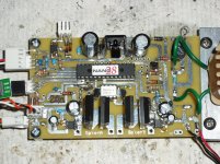
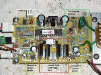
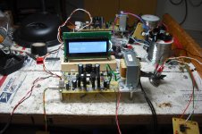
Right now I am working in a project that control the speaker outputs using solid state relays by monitoring the current going to the speakers. If for any reason the current reach the trip setting it will open the relays immediately and enable the mute. If the output it is shorted the relays will be open protecting the speakers from burning up and the amplifier transistors outputs. I am sensing the speakers current going to ground. Attached it is picture of my controller. Also slowly ramp up/down the AC at zero crossing when the amplifier it is turn ON/OFF. This is to prevent the inrush current from the transformer. Finally also it monitor the temperature of the heat sink and will shutdown the amplifier if the temperature reach the trip setting. Attache it is the a picture of the controller.
PM what you want and I will look into and may come up with a circuit design using the micro.
Attachments
Tauro, this is nice work, although a bit more effort to assemble than I'm looking to do. Just came across this speaker protector board, which looks simple enough. It includes relays to interrupt speaker outputs when mains power is cut, and a few seconds of delay timer on power up. An 8 channel system would need four of these boards.
Hi,
Right now I am working in a project that control the speaker outputs using solid state relays
What are the solid state relays please?
Frank
- Status
- This old topic is closed. If you want to reopen this topic, contact a moderator using the "Report Post" button.