light bulb "regulator" question.
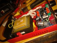
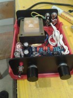
i was bored and had no 7815 ,7915 regulators at hand to finish ebay bought subwoofer crossover, as i re used regulators in something more importatnt.so in their place i put two 300ohm resistors to achieve virtual ground,and small 5w bulb in series with 24v ac trafo secondary, then diode bridge , on output i have very silent 20.5volts dc.
question is, is there possibility that this produces some problem in future, i am not aware of now. bulb is barely lit and not hot. is this safe 100% to use this way? nothing is hot and it plays nice .
thank you for your time.
Attachments
is there possibility that this produces some problem in future, i am not aware of now.
bulb is barely lit and not hot. is this safe 100% to use this way? nothing is hot and it plays nice .
It's an RC filter, somewhat like an LC filter but with less sharp filtering
and some DC loss. This is not regulated, so the voltage can vary,
and could possibly damage the circuit from over-voltage.
Last edited:
Well, one could argue that an incandecent lamp works more like an PTC thermistor.
Higher temp = higher resistance So there is some kind of current regulation/limiting happening.
Pretty bad circuit.
Well, yes.Pretty bad circuit.
Might be better to use a bulb that would run closer to spec. Then it can function like a fuse.

pretty bad i agree but i had no regulators at hand , and hoped this is safer than runing opamps on 31v where in datasheet says its limit 30v, it worked but i had bad feeling it will blow when i need it most. there is probability that this circuit will be connected to small generator ,or inverter from time to time so i wanted to be 100% sure that this will work from 220-240v ,at 235v it was 31v dc at opamp pins without bulb, with bulb 20.5v. now i was concerned that it has any other negative effect that i am not seeing now.
i hope it is safe to work on 240v mains as it is working on 20v on 235v mains. i am still testing it and it is working for almost 5 hours now and even boxed there is no noticable heating, maybe few degrees over ambient.
edit:thank you m8e i forgot to put fuse
the bulb is fully lit when capacitors are charging
What DF96 said, bulbs are *constant current* devices, even plain resistors are better than them.
Anyway, you were out of regulators on Saturday or Sunday and tried this ... you got lucky .... fine ....................... so far.
But today shops are open so go get the proper regulators, you have no excuse for that.
If you are dreaming about leaving that circuit as-is forever ... forget it.
Now you have an anti-regulator which will do the opposite of what you need, it will *amplify* mains voltage variations.
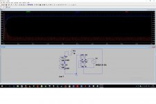
Simulating a different circuit from the one you have built will not give much useful information.tonitonitoni said:here is sim, but with resistor i dont know how to put bulb resistance in ltspice
Now you have an anti-regulator which will do the opposite of what you need, it will *amplify* mains voltage variations.
It really depend on how the load behave. Would the current go up with a higher input voltage? In that case you also get an higher voltage drop over the bulb.
Higher input voltage -> higher current -> higher voltage drop over the bulb.
i have bought 7815 and 7915 today.. but i will leave it as is for few days to check how it works on inverter , if it works i will use 78xx in other circuit. i realy cant wrap my head around this anti regulator that you saying.i think at no load or low load as opamps it behaves good. load is two opamps ,4558c
Last edited:
It probably seems to work because of the low current. Does the bulb ever light up or change intensity? If yes then the resistance is going up so there's more voltage drop across the bulb lowering the opamp voltage. So the more current thru the opamps means lower supply voltage. Think of a pot instead of the light bulb. And as the circuit draws more current you increase the resistance of the pot. The way to simulate is to replace the bulb with a current controlled resistor where the resistance increase with current. (A thermistor).
If you just have 2 dual Op Amps, which means around 6 mA total load, just use 2 resistors which allow to pass, say, 10 to 20 mA (apply Ohm's Law) , plus two 15/16V Zeners from +/- rails (pins 8 and 4) to ground and forget the regulators, the bulky/cheesy bulbs and anything else.
Decouple the +/- rails with electrolytics from 10 to 100uF and if you wish, .1 or .05 ceramic caps nearby.
I can tell you something, an Op Amp is not a resistive load, so treating it as such does not really help you.
And in any case, I don't understand how a *floating* current regulator (that's what the lightbulb is) , which has no clue on the original raw voltage nor on the load required one, could help regulate the latter operating voltage.
Decouple the +/- rails with electrolytics from 10 to 100uF and if you wish, .1 or .05 ceramic caps nearby.
It really depend on how the load behave. Would the current go up with a higher input voltage? In that case you also get an higher voltage drop over the bulb.
Higher input voltage -> higher current -> higher voltage drop over the bulb.
I can tell you something, an Op Amp is not a resistive load, so treating it as such does not really help you.
And in any case, I don't understand how a *floating* current regulator (that's what the lightbulb is) , which has no clue on the original raw voltage nor on the load required one, could help regulate the latter operating voltage.
Last edited:
- Status
- This old topic is closed. If you want to reopen this topic, contact a moderator using the "Report Post" button.
- Home
- Member Areas
- The Lounge
- quick ,dirty voltage lowering with light bulb