There it is. Does zero THD = no nonlinearity = zero IMD?
A lot of people complain that THD is not reflective of SQ, and that IMD is much more irritating.
Could we set an upper bound to the IMD based on the THD?
A lot of people complain that THD is not reflective of SQ, and that IMD is much more irritating.
Could we set an upper bound to the IMD based on the THD?
There it is. Does zero THD = no nonlinearity = zero IMD?
A lot of people complain that THD is not reflective of SQ, and that IMD is much more irritating.
Could we set an upper bound to the IMD based on the THD?
You would have a hard time contriving a physically real circuit with that property. In general this is not possible
Non-zero THD and non-zero IMD are both created by nonlinearity, so they are unlikely to differ very much. It is possible, to a limited extent, to vary one without varying the other so I suppose this could be done by accident.
For example, a cathode decoupler (or screen grid decoupler) might adequately decouple audio frequencies but not subsonics. Two tones separated by a small frequency shift might separately generate harmonics (and so contribute to THD) and together generate second-order IMD at their sum and difference frequencies. The difference frequency IMD could appear across the inadequate decoupling cap and so create extra re-entrant distortion which will appear as further (third-order) IMD. Thus varying the capacitor value will vary the IMD but not the THD. However, the source of both THD and IMD are the same (device) nonlinearity.
I would say that in most cases you can estimate either from the other.
No definitive answers, just some additional information:There it is. Does zero THD = no nonlinearity = zero IMD?
A lot of people complain that THD is not reflective of SQ, and that IMD is much more irritating.
Could we set an upper bound to the IMD based on the THD?
http://www.diyaudio.com/forums/equipment-tools/188169-low-distortion-oscillator-3.html#post2559836
http://www.diyaudio.com/forums/soli...values-below-thd-values-ss-amps-possible.html
Sometimes, a sufficiently high intermodulation level can drive away THD (and lower frequency IM products):
http://www.diyaudio.com/forums/solid-state/252143-dive-into-past.html
I would say that in most cases you can estimate either from the other.
That's more what I was suggesting, but I was wondering about an absolute calculation.
Forgive me if my mathematical definitions are letting me down, but isn't the THD a consequence of the transfer function? And the IMD a similar consequence of the transfer function? So if we took all the harmonic power and put it in the (say) the second, could we calculate the worst case IMD for any 2 inputs? I hate trig, and Laplace is rusty.
Or just plot a load of points, THD vs. IMD, and see if we can draw a line through them?
Thanks for the links Elvee. I didn't know there was existing conversation.
Yes, and in fact you could say that only IMD exists, the THD being a particular case/subset of the more general IMD, where the signal intermods with itself.Forgive me if my mathematical definitions are letting me down, but isn't the THD a consequence of the transfer function? And the IMD a similar consequence of the transfer function?
Specific differences seem to appear, but they are caused by the fact that certain products cancel each other: a typical and extreme example is a symetrical clipping circuit, where all the even products cancel between the positive and negative half-cycles
If you take a simple system, with no filters etc., then the harmonic and intermodulation distortion arise from the same nonlinearity so must be equal. As Elvee says, harmonic distortion is merely a special case of IMD.
Real systems are not quite so simple, but it is still true that most distortion arises in the same way. My suspicion is that people who wish to completely separate harmonic distortion from IMD simply don't know enough algebra and trigonometry, so they can't understand how distortion products arise from nonlinearities.
Real systems are not quite so simple, but it is still true that most distortion arises in the same way. My suspicion is that people who wish to completely separate harmonic distortion from IMD simply don't know enough algebra and trigonometry, so they can't understand how distortion products arise from nonlinearities.
To a first approximation, I would expect THD and IMD to measure the same, since as pointed out above, THD is just IMD with 2 tones of the same frequency.
So for example I would expect the 10kHz THD measurement to be roughly the same as the 10+11kHz IMD and so on. IMD might measure somewhat greater than THD at high frequencies, because more of the harmonic energy ends up in band. If you measure 20kHz THD with an 80kHz measurement bandwidth, you start to lose energy beyond the 4th harmonic. But the 4th order IMD product of a 19+20kHz test signal is at 2kHz.
This is also the reason why IMD might be perceived as "more irritating than THD" (though this is inaccurate as IMD and THD are not separate phenomena, they're two ways of measuring the same nonlinearity) If you take a sluggish solid-state amp and wrap lots of feedback around it, you get THD that looks good at 1kHz but increases rapidly at high frequencies. You can make this look good by measuring with an 80kHz bandwidth to exclude most of the harmonics. But if you do a 19+20kHz IMD test, or listen to music with complex high frequency content through it, things don't look so great.
For people who use soundcards to measure amplifier performance, these considerations are even more important. Even if you run at 96kHz, you can only see the 2nd harmonic of a 20kHz THD test, everything else is brickwall filtered away. You will get more useful results by doing IMD testing instead, assuming your soundcard actually has good IMD performance.
actually IMD products are reduced by the amount of feedback at the product frequency just like any other error measured by the input stage
so its expected for a dominant pole compensated high loop gain amp to have ~40x less 1 kHz IMD vs 39 kHz in the 19k+20k test
so its expected for a dominant pole compensated high loop gain amp to have ~40x less 1 kHz IMD vs 39 kHz in the 19k+20k test
people do the 2-tone IMD, multitones with real hardware too - including Groner
Hofer and Cabot at AudioPrecision have several articles that are useful if you want to know how audio systems are measured by actual professional engineers, what test signals are "standard" nowadays (for many decades actually)
as you increase the number of frequencies in a multitone you have to decrease the level of each frequency component - greatly reducing sensitivity for higher order distortion mechanisms
single sine harmonic distortion and 2-tone IMD sweeps in level and frequency do find almost everything unless you have deliberately designed multiple frequency filters feeding analog multipliers and summing them in your output
I use 2-tone in sim quite often, with a modern PC, LTspice it really isn't a problem to do with fine enough time step, long enough # of periods
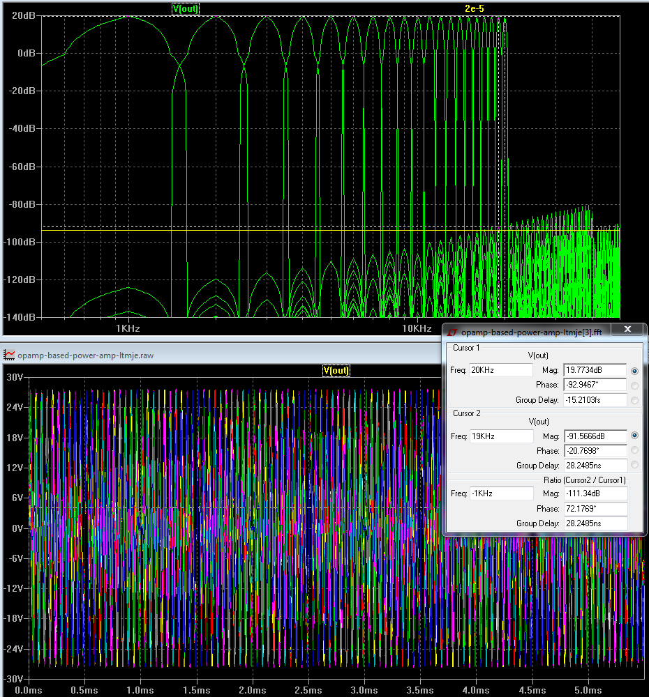
looking at the .tran distortion sim a interesting test is to use 2 sine inputs in series, 1:1 level of 600mV each to give near full output, fix one at 20 KHz, step the other from 1k to 19k in 1 kHz steps - the critical measure of quality is the IMD products below 20 kHz - also has the harmonic distortions of the lower tone
when this stepped 2-tone is done you can plot the combined fft, see just how "bad" the "rising distortion with frequency" is (not)
the yellow line is ~ -120 dB re the peak of the combined 2 tones
you can see all audio frequency harmonics of the 1-19 kHz stepped frequency tones and the IMD difference products of all orders with the 20 kHz constant tone
all audio frequency distortions just barely breaks above -120 dB below the combined 2 tone peak amplitude in the 18, 19 kHz bins - with the original op amp
the level of all of the audio band distortions are all inaudible - below human hearing threshold in quiet if the speaker were giving 120 dB SPL with the amp's full output
with higher loop gain op amp you can keep every audio frequency distortion product below -120 dB in the sim
Last edited:
Yes. It is surprising how often this is ignored or even denied. It could be part of the reason why some (SS?) people often claim that THD and IMD are separate phenomena.jcx said:actually IMD products are reduced by the amount of feedback at the product frequency just like any other error measured by the input stage
It certainly flies in the face of the received wisdom about "delayed feedback" and "distortion of a distortion". Yup folks, feedback actually works. 😀
If memory serves, Norman Crowhurst showed a transfer function that had IM but not HD in his article about amplifier sound-measurements correlation. It wasn't a particularly physical transfer function and I think the HD cancellation was rather level dependent, so that doesn't change reality- HD measurements show any actual nonlinearity of a real box of gain.
Not really relevant for the discussion, but just because it occurred to me -
You could get the opposite, nonzero THD but effectively zero IMD. Just have the two test tones for IMD come through different nonlinear paths, such as different drivers like a woofer and tweeter with ideal filter crossovers. It's a trick done in telephone towers, to keep signals from intermodulating by isolating them with filters from sharing the same nonlinearities before recombining them. But that depends on the test frequencies of course, you could choose different frequencies where the signals do intermodulate within one of the same paths.
And as mentioned earlier, you could get zero HD but non-zero IMD by just using a low pass filter that blocks out high harmonic frequencies but passes IMD product frequencies.
At the end of the day, IMD and HD only define the tests used to look for nonlinearity, not the nonlinearity itself.
Last edited:
Nevertheless, the main point remains: you need to specially engineer a system in order to get significant difference between harmonic and IMD levels (apart from simple filter issues). Unlikely to happen by accident, if the aim is to amplify audio.
Hi,
The simple fact is without the THD spectrum you can't
say anything about the IMD spectrum, and though THD
might relate to total IMD in simple number terms,
it is true that zero THD implies zero IMD.
Distortion can be irritating, however you measure it.
FWIW everyone knows speakers distort more than
amplifiers. However the THD and IMD both have
spectra implying most of the distortion is low order
with very little high order. Similar to valve amplifiers.
However solid state can have a low level even spray
of harmonics to a very high order (at least the 40th for
500Hz) and produces a hugely different IMD spectrum.
THD and total IMD numbers are useless at predicting quality.
(As numbers without any context whatsoever.)
rgds, sreten.
To measure IMD, the DUT need to be fed (at least) 2 tones.
To measure THD, the DUT need to be fed only one tone as if one would measure THD feeding the DUT 2 tones, the second would be seen as distorsion.
If a third tone (or more), T3, appears while doing a 2 tone (T1 & T2) IMD measurement we have IMD.
So, is it theroticlly possible that:
DUT is fed T1 and T2, and, any sum or diff of T1/2 is filtered out, and, (e.g.) T2 is filtered out; output show T1 and zero THD?
The little problem here is that the feedback loop has to work "perfectly" for all the benefits to be realised. And it doesn't take much effort simulating real word screnarios to see how that behaviour can be very easily disturbed by real world parts not working "perfectly" ... hence some of the subjectively disturbing distortion in real world audio systems ...It certainly flies in the face of the received wisdom about "delayed feedback" and "distortion of a distortion". Yup folks, feedback actually works. 😀
No, it just has to work adequately.fas42 said:The little problem here is that the feedback loop has to work "perfectly" for all the benefits to be realised.
Anyway this is what I was kind of thinking...
I haven't identified variables but more or less followed convention but Q(s) is the 2-tone input.
Y(s)=H(s)X(s)
H(s)=Y(s)/X(s)
IMD(s)=Q(s)H(s)
L-1{Y(s)}=f(t)=(1-b)sin(wt)+b(sin(2wt)) (fundamental + 2nd. harm output)
L-1{X(s)}=f(t)=sin(wt) (input)
L-1{Q(s)}=f(t)=0.5(sin(wt))+0.5(sin(qwt))
Y(s)=((1-b)w)/(w^2+s^2)+2wb/(4w^2+s^2)
X(s)=w/(w^2+s^2)
Q(s)=0.5w/(0.25w^2+s^2)+0.5qw/(0.25q^2w^2+s^2)
H(s)=((1-b)w/(w^2+s^2)+2wb/(4w^2+s^2))/(w/(w^2+s^2)
IMD(s)=(0.5w/(0.25w^2+s^2)+0.5qw/(0.25q^2w^2+s^2))(((1-b)w/(w^2+s^2)+2wb/(4w^2+s^2))/(w/(w^2+s^2))
Then I'd have to simplify that, hoping to get a lot of cancellation, and take L-1
Or am I barking up the wrong tree? Or simply barking?
Anyway this is what I was kind of thinking...
I haven't identified variables but more or less followed convention but Q(s) is the 2-tone input.
Or am I barking up the wrong tree? Or simply barking?
Something like the "ITT Reference Data for Radio Engineers" has the basic algebraic derivations already done for you.
- Status
- Not open for further replies.
- Home
- Member Areas
- The Lounge
- Can you have zero THD and nonzero IMD?