Yes and no. Yes, magnetic and electric fields are different. No hysteresis is a universal concept and implies anisotropy.
It's easier to see this just defining hysteresis according to its original meaning: physical variable (electric polarization P in the case of dielectrics) lagging behind changes of what is causing it (electric field in the case of dielectrics).
As the polarization in REAL capacitors ALWAYS lags behind the applied electric field (because the response to an applied field in NEVER instantaneous) once the field is removed there will be a residual polarization which depends on the materials properties. Typically, the residual voltage is about 1% for polymer capacitor (actually quite less for best types) and up to 15-20% for electrolytic capacitors. The lag depends on the materials properties and thus one can describe the polarization as the sum of an induced polarization that depends on the electric field and a residual polarization independent of the electric field. If there is a polarization component which does not depend on the electric field it means that there is a dielectric anisotropy just like the magnetic anisotropy in ferromagnetic material. The residual voltage can take a short or long time to disappear depending on the dielectric type and leakage.
Hysteresis is material related. The Science of hysteresis is one general theory and applies to both dielectrics and magnets.
The sample preparation issue has not necessarily a role in hysteresis. Dislocations, defects and similar things in principle cause energy storage which has nothing to do with hysteresis (and the relative hysteresis loss) in principle. Dislocations, defects etc. might have a role in practice but not necessarily and they can be neglected tout-court in theory for a structurally perfect material. Structurally perfect materials can have hysteresis anyway.
Practical materials for capacitors do have hysteresis loss to some extent, some very small and some more, and this mostly is caused by the lagging of polarization respect to the applied electric field which allows to describe polarization in terms of field dependent and field independent components of total polarization. If there is a field independent polarization then there is anisotropy. I think you confuse field dependence with time dependence. Actually I am pretty sure.
I think you have to go back to school and then you might be able to re-enter the debate!
Awesome !
Took me twenty post to explain the idea, and you, on only two succeeded in synthesizing the entire concept.
What more can I add? You've left me speechless.
Chapeau !


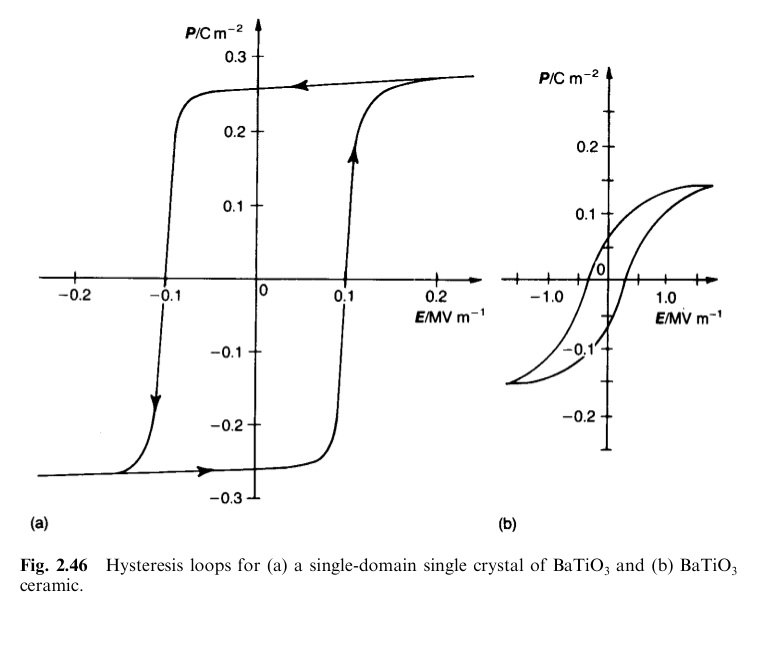
Just to make things a bit more clear this is a picture that represents one striking example of the hysteresis of final capacitor compound in comparison to the original pure dielectric material. The BaTiO3 is widely used in industry in the form of multilayered ceramic capacitor of course. The perfect single crystal does have a clear square hysteresis loop and this is "softened" in a real ceramic capacitor. So the sample preparation does have an effect but certainly not the effect to transform a material with no hysteresis into one with hysteresis. It is ferroelectric on its own.
Attachments

Last edited:
Due to my Tarzan-English, I am the less appropriate on the planet, even to give a spoof English lesson, however, what amazes me is that nobody, both English and French native language realized that, regardless of the "ignore" meaning, the English translation is wrong anyway
The English translation "is as if" authors say "we have no idea about hysteresis"
It amazes me that you assume that the English speaker would read the translation that way, please stick to physic and leave the Tarzan English to us "native speakers"...😀
It amazes me that you assume that the English speaker would read the translation that way, please stick to physic and leave the Tarzan English to us "native speakers"...😀
You can make fun of me, even you can misquoted me (chronologically), but what you cannot, is hide the truth under the carpet.
Just in order to help people who can have the English translation, I quoted both.
The whole of the discussion in this chapter concerns only thermodynamic equilibrium states in ferromagnetics and therefore reversible processes in them.
In particular, we entirely ignore the mechanism of hysteresis phenomena; these may arise from defects in the crystal, internal stresses, a polycrystalline state, and so on.
As seems to me that nobody understood, it reminds me a joke.Dans ce chapitre, nous nous limitons aux états des corps ferromagnétiques en équilibre thermodynamique et, par conséquent, aux processus réversibles.
En particulier, nous n'abordons pas le mécanisme des effets d'hystérésis qui peuvent être liés aux défauts du cristal, aux contraintes internes dans l'échantillon, à la polycristallinité, etc.
The analogy is immediateThe listener was standing behind someone who apparently had more than a dozen items in a supermarket express checkout line in Cambridge. When the person in front arrived at the counter, the cashier then pointed to the sign “Express line: 10 items or fewer only". She then said: “You must be from MIT or Harvard,” the two big universities in town. The guy smiled and said: “Yeah, how do you know?". The cashier said: “You must be from MIT because you can’t read or you must be from Harvard because you can’t count.”
If you can't understand the difference, two possibilities
You can't read or you can't understand physics.
Just to make things a bit more clear this is a picture that represents one striking example of the hysteresis of final capacitor compound in comparison to the original pure dielectric material. The BaTiO3 is widely used in industry in the form of multilayered ceramic capacitor of course. The perfect single crystal does have a clear square hysteresis loop and this is "softened" in a real ceramic capacitor. So the sample preparation does have an effect but certainly not the effect to transform a material with no hysteresis into one with hysteresis. It is ferroelectric on its own.
Great !
It gives me an idea about why people are so confused.

Please, give me more time, I am working on another rough demonstration. 😉
You can make fun of me, even you can misquoted me (chronologically), but what you cannot, is hide the truth under the carpet.
Stop with the personal attacks already... How am I misquoting you, I merely took the sentences that you wrote yourself and suggested that just may be you were mis-interpretting how the English speakers would read that quoted passage. How is "entirely ignore" = "is as if" authors say "we have no idea about hysteresis"? It simply states that hystersis is not considered in the context of the particular subject matter. Don't make it into something that it is not.🙂
Stop with the personal attacks already...
Let me leave perfectly clear that I have nothing personal against you, on the contrary, since I commit the clumsiness of find inconsistencies on the mathematical models of your friend, here
http://www.diyaudio.com/forums/tubes-valves/243950-vacuum-tube-spice-models-13.html#post3749445
Your posts became more and more aggressive against me, at the point of being systematic
http://www.diyaudio.com/forums/loun...sformers-valve-amplifiers-28.html#post3882785
so i wonder for what prupose poppilin would like to argue "theories" ad infinitum....
come on now, how is he going to get his kicks and look down at all the theory-challenged poor souls? 🙄
Due to my Tarzan-English, I am the less appropriate on the planet, even to give a spoof English lesson, however, what amazes me is that nobody, both English and French native language realized that, regardless of the "ignore" meaning, the English translation is wrong anyway
It amazes me that you assume that the English speaker would read the translation that way, please stick to physic and leave the Tarzan English to us "native speakers"...😀The English translation "is as if" authors say "we have no idea about hysteresis"
If your purpose is make fun of my Tarzan-English, go ahead, I myself do it quite more often.
If your purpose is to persecute me, thread after thread, I consider that already it is enough.
Finally, if the topic of this thread is not of your interest/taste, mind you that there are thousands more about there... 🙂
Can exists the possibility that many people could have false assumptions/misunderstandings ?
A long ago, speculating about transformers, I seen this
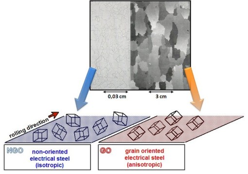
But, wait a moment, if NOSS is isotropic, then no hysteresis at all, why waste my little money on costly GOSS ?
Ah, silly me, that explains all, at microscopic level magnetic domains are anisotropic, but macroscopically, lamination is isotropic.
But, this is a contradiction, what about hysteresis ?
Mmmm...seems to me that something is wrong,…indeed, the answer here
Introduction to the Theory of Ferromagnetism (International Series of Monographs on Physics): Amikam Aharoni: 9780198508090: Amazon.com: Books
A profound explanation at chapter 5, in few words:
Real world magnetic materials are not isotropic.
Then, you must not believe on all that internet says. 😉
Now, I am working on the analogy for dielectric materials and a more complete explanation, this is only provisory.
I'll be back soon...I hope...I think slowly. 😀
A long ago, speculating about transformers, I seen this
But, wait a moment, if NOSS is isotropic, then no hysteresis at all, why waste my little money on costly GOSS ?
In a single crystal, the physical and mechanical properties often differ with orientation. It can be seen from looking at our models of crystalline structure that atoms should be able to slip over one another or distort in relation to one another easier in some directions than others. When the properties of a material vary with different crystallographic orientations, the material is said to be anisotropic.Anisotropy and Isotropy
Alternately, when the properties of a material are the same in all directions, the material is said to be isotropic. For many polycrystalline materials the grain orientations are random before any working (deformation) of the material is done. Therefore, even if the individual grains are anisotropic, the property differences tend to average out and, overall, the material is isotropic.
Ah, silly me, that explains all, at microscopic level magnetic domains are anisotropic, but macroscopically, lamination is isotropic.
But, this is a contradiction, what about hysteresis ?
Mmmm...seems to me that something is wrong,…indeed, the answer here
Introduction to the Theory of Ferromagnetism (International Series of Monographs on Physics): Amikam Aharoni: 9780198508090: Amazon.com: Books
A profound explanation at chapter 5, in few words:
Real world magnetic materials are not isotropic.
Then, you must not believe on all that internet says. 😉
Now, I am working on the analogy for dielectric materials and a more complete explanation, this is only provisory.
I'll be back soon...I hope...I think slowly. 😀
Attachments

Last edited:

But I want to listen EXACTLY to what authors (musicians, producers, engineers) intended.
good luck 😀
Dear Lars
I'm sorry to answer so late, but wherever you are now, I want to say you that your joke is on the top five, and I always will remember you with a smile. 🙂

Another rough demonstration
Part 1 – Ferromagnetic Materials
I will follow Landau-Lifshitz approach [1], with little changes
[*], because it can't be more clear and easier, intuitively based on solid physical foundations without loosing on mathematics.
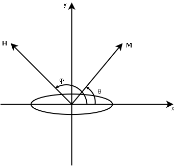
Let’s consider a single domain, uniaxial magnetic particle with magnetization M, under the influence of a magnetic field H
Magnetic anisotropy energy is given by
Where θ is the angle between M and the x-axis, taken to be along the principal axis of symmetry, the so called easy axis, and β is a constant which depends on temperature.
After some thermodynamic considerations, and a few calculations we obtain
Taking the derivative with respect to θ
Eliminating θ from these two equations gives
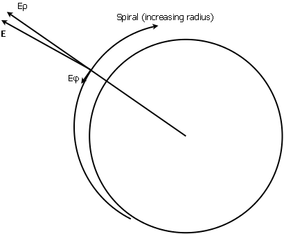
In the Hx Hy plane this represents the so called astroid curve

This is the clearest way to see how varies hysteresis with anisotropy. Not shown in the book because Landau-Lifshitz presupposes some basic understanding.
For φ = 0, along the easy axis, anisotropy reaches its maximum and also does hysteresis.
For φ = π/2, along the hard axis, which effectively means no anisotropy at all, also does hysteresis, i.e. no hysteresis at all.
[*] Ex profeso, I changed the axes of coordinate system, so equations and graphs are completely different as those of the book, just in case someone wants to make copyright claims, furthermore, most textbooks follow the same approach adorned with more equations, so no need to reinvent the wheel.
At macroscopic level one can use the old trick to say that, for a magnetic domain macroscopically small and microscopically large, demonstration above is also valid.
Anisotropy/hysteresis will be in between both extremes, i.e. something similar to the case for 0<φ<π/2.
The understanding of magnetic anisotropy and how it can be controlled is the key factor in order to improve the properties of magnetic materials, e.g. amorphous and nanocrystalline alloys.
But again, don't dream, isotropic magnetic materials don't exist in real world. [2]
[1] L. D. Landau, E. M. Lifshitz. Electrodynamics of Continuous Media. Course of Theoretical Physics Vol 8. Pergamon Press.
[2] Amikam Aharoni. Introduction to the Theory of Ferromagnetism. Oxford Science Publications.
Part 1 – Ferromagnetic Materials
I will follow Landau-Lifshitz approach [1], with little changes
[*], because it can't be more clear and easier, intuitively based on solid physical foundations without loosing on mathematics.
Let’s consider a single domain, uniaxial magnetic particle with magnetization M, under the influence of a magnetic field H
Magnetic anisotropy energy is given by
ℇanisotropy = ½ β M² sin²θ
Where θ is the angle between M and the x-axis, taken to be along the principal axis of symmetry, the so called easy axis, and β is a constant which depends on temperature.
After some thermodynamic considerations, and a few calculations we obtain
(Hy / sinθ) - (Hx / cosθ) = β M
Taking the derivative with respect to θ
(Hx / cos³θ) + (Hy / sin³θ) = 0
Eliminating θ from these two equations gives
Hx ²/₃ + Hy ²/₃ = (β M) ²/₃
In the Hx Hy plane this represents the so called astroid curve
This is the clearest way to see how varies hysteresis with anisotropy. Not shown in the book because Landau-Lifshitz presupposes some basic understanding.
For φ = 0, along the easy axis, anisotropy reaches its maximum and also does hysteresis.
For φ = π/2, along the hard axis, which effectively means no anisotropy at all, also does hysteresis, i.e. no hysteresis at all.
[*] Ex profeso, I changed the axes of coordinate system, so equations and graphs are completely different as those of the book, just in case someone wants to make copyright claims, furthermore, most textbooks follow the same approach adorned with more equations, so no need to reinvent the wheel.
At macroscopic level one can use the old trick to say that, for a magnetic domain macroscopically small and microscopically large, demonstration above is also valid.
Anisotropy/hysteresis will be in between both extremes, i.e. something similar to the case for 0<φ<π/2.
The understanding of magnetic anisotropy and how it can be controlled is the key factor in order to improve the properties of magnetic materials, e.g. amorphous and nanocrystalline alloys.
But again, don't dream, isotropic magnetic materials don't exist in real world. [2]
[1] L. D. Landau, E. M. Lifshitz. Electrodynamics of Continuous Media. Course of Theoretical Physics Vol 8. Pergamon Press.
[2] Amikam Aharoni. Introduction to the Theory of Ferromagnetism. Oxford Science Publications.
Attachments


Another rough demonstration
Part 2 – Dielectric Materials
A more general form to write constitutive relation for a dielectric medium is
Where
D₀i are constants in order to contemplate the case
εij(ω) is the rank 2 permittivity tensor, from Thermodynamics, it can be proved that in most cases it must be symmetric, i.e. εij = εji, and it is always possible to choose coordinate systems in that this tensor is diagonal, i.e. εij = 0, i ≠ j
1) The medium is Isotropic
Then
i) The response of the medium is Linear
Then, ε(ω), must be a real linear function.
The curve D=f(E) must be an open curve, so no hysteresis.
In the particular case of an Homogeneous medium
With ε=constant, then the curve D=f(E) must be a straight line, so no hysteresis.
ii) The response of the medium is Nonlinear
Then, ε(ω), must be a real nonlinear function, and again, the curve D=f(E) must be an open curve, so no hysteresis.
2) Let's consider now a Nonlinear Anisotropic single domain/crystal with its more simple uniaxial symmetry, then we can write
With chosen coordinate system, a rotation around z-axis does not change anything, i.e. within the x y plane a uniaxial crystal is isotropic.
It can be proved that, if we apply an electric field E out of the x y plane, the curve D=f(E) is a closed curve, then we have hysteresis.
Same reasoning, another formulation, applies to biaxial symmetry.
Then, anisotropy and nonlinearity are necessary conditions for hysteresis, conversely, hysteresis implies both anisotropy and nonlinearity.
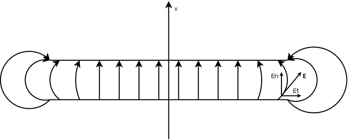
As an example of how capricious can be real world, let's consider now the case of an electric field E applied on the x-axis direction, and let's also suppose that really exist a dielectric material which can be perfectly isotropic along x-axis.
Contrary to all preconceptions, this is not an impediment to have hysteresis.
The reason for this cannot be simpler: Real world capacitors are not perfect infinite parallel plane plates, at least those that I can buy on this side of the world, never knows...
Not a contradiction at all, even on the case where anisotropy can be ignored, on the real world it can't.
Note that W. Thomson (Lord Kelvin) had a dirty trick to approximate the behavior of an infinite plane capacitor, but I hate the idea to see in the future "gold foil snake oil Kelvin type audio grade capacitors", then I will remain silent, but maybe it is too late, never knows...
Unfortunately, real world capacitors are far to be ideal, edge effects are greater because of their construction.

With other geometry, e.g. cylindrical axial capacitors, things are even worse, because equipotential surfaces are not perfectly concentric cylinders, then exists a tangential component of electric field E along the whole dielectric, not only at the edges.
Additional notes
Just in case someone escaped him the turtle, we must remember that constitutive relations have the same mathematical form both for magnetic media as for dielectric media, then analogies are valid and the problem admits a general demonstration using Tensor Geometry.
Furthermore, as permittivity tensor can't know if we are analyzing a single microscopic domain, or a macroscopic sample, demonstration applies on both cases, anyway, this is a rough demonstration, not a treatise on condensed matter physics.
However, passing from one or two symmetry axes (uniaxial and biaxial anisotropy), to an infinite number of symmetry axes (isotropy), is a lot difficult even to imagine it.
Part 2 – Dielectric Materials
A more general form to write constitutive relation for a dielectric medium is
Di = D₀i + εij(ω) Ej
Where
D₀i are constants in order to contemplate the case
D (E=0 , ω=0) ≠ 0
εij(ω) is the rank 2 permittivity tensor, from Thermodynamics, it can be proved that in most cases it must be symmetric, i.e. εij = εji, and it is always possible to choose coordinate systems in that this tensor is diagonal, i.e. εij = 0, i ≠ j
1) The medium is Isotropic
D₀i = 0, i=1,…,3
ε11(ω) = ε22(ω) = ε33(ω) = ε(ω) ∈ ℝ
Then
D = ε(ω) E
i) The response of the medium is Linear
Then, ε(ω), must be a real linear function.
The curve D=f(E) must be an open curve, so no hysteresis.
In the particular case of an Homogeneous medium
D = ε E
With ε=constant, then the curve D=f(E) must be a straight line, so no hysteresis.
ii) The response of the medium is Nonlinear
Then, ε(ω), must be a real nonlinear function, and again, the curve D=f(E) must be an open curve, so no hysteresis.
2) Let's consider now a Nonlinear Anisotropic single domain/crystal with its more simple uniaxial symmetry, then we can write
ε11(ω) = ε22(ω) = ε∥(ω) ∈ ℂ
ε∥(ω) = ε’∥(ω) + i ε’’∥(ω) = ∣ε∥(ω)∣ [cos (δ∥) + i sin (δ∥)]
ε33(ω) = ε⊥(ω) ∈ ℂ
ε⊥(ω) = ε’⊥(ω) + i ε’’⊥(ω) = ∣ε⊥(ω)∣ [cos (δ⊥) + i sin (δ⊥)]
ε∥(ω) = ε’∥(ω) + i ε’’∥(ω) = ∣ε∥(ω)∣ [cos (δ∥) + i sin (δ∥)]
ε33(ω) = ε⊥(ω) ∈ ℂ
ε⊥(ω) = ε’⊥(ω) + i ε’’⊥(ω) = ∣ε⊥(ω)∣ [cos (δ⊥) + i sin (δ⊥)]
With chosen coordinate system, a rotation around z-axis does not change anything, i.e. within the x y plane a uniaxial crystal is isotropic.
It can be proved that, if we apply an electric field E out of the x y plane, the curve D=f(E) is a closed curve, then we have hysteresis.
Same reasoning, another formulation, applies to biaxial symmetry.
Then, anisotropy and nonlinearity are necessary conditions for hysteresis, conversely, hysteresis implies both anisotropy and nonlinearity.
********************************************
Anisotropy + Nonlinearity ⇔ Hysteresis
********************************************
As an example of how capricious can be real world, let's consider now the case of an electric field E applied on the x-axis direction, and let's also suppose that really exist a dielectric material which can be perfectly isotropic along x-axis.
Contrary to all preconceptions, this is not an impediment to have hysteresis.
The reason for this cannot be simpler: Real world capacitors are not perfect infinite parallel plane plates, at least those that I can buy on this side of the world, never knows...
Not a contradiction at all, even on the case where anisotropy can be ignored, on the real world it can't.
Note that W. Thomson (Lord Kelvin) had a dirty trick to approximate the behavior of an infinite plane capacitor, but I hate the idea to see in the future "gold foil snake oil Kelvin type audio grade capacitors", then I will remain silent, but maybe it is too late, never knows...
Unfortunately, real world capacitors are far to be ideal, edge effects are greater because of their construction.
With other geometry, e.g. cylindrical axial capacitors, things are even worse, because equipotential surfaces are not perfectly concentric cylinders, then exists a tangential component of electric field E along the whole dielectric, not only at the edges.
Additional notes
Just in case someone escaped him the turtle, we must remember that constitutive relations have the same mathematical form both for magnetic media as for dielectric media, then analogies are valid and the problem admits a general demonstration using Tensor Geometry.
Furthermore, as permittivity tensor can't know if we are analyzing a single microscopic domain, or a macroscopic sample, demonstration applies on both cases, anyway, this is a rough demonstration, not a treatise on condensed matter physics.
However, passing from one or two symmetry axes (uniaxial and biaxial anisotropy), to an infinite number of symmetry axes (isotropy), is a lot difficult even to imagine it.
Attachments


Last edited:
Another rough demonstration
Part 3 – More Anisotropy
Isotropy is a difficult thing in the real world, to the point that even the vacuum isotropy is discussed today.
As well as Schrödinger's cat can not be, nor half-alive, neither half-dead, Schrödinger's mistress can not be half-pregnant.
If a material is infinitesimally anisotropic, then it cannot be isotropic.
But surprise!!! I have found some measurements!!! [1]
The dielectric anisotropy can be expressed as normalized ratios
Curiously, "practically isotropic" materials exhibit some degree of anisotropy, e.g.
i) PTFE, 0.945 mm thickness
ii) Polyolefin, 0.7725 mm thickness
iii) Polycarbonate, 1.000 mm thickness
iv) Polycarbonate Lexan® D-sheet, 0.51 mm thickness
Although author's effort on discredit his own measurements, this gives us a clue about what really happens with real world dielectrics. [2], [3], [4]
A picture is worth a thousand words
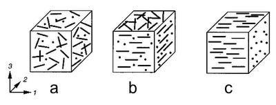
A bulk material can be "practically isotropic", "almost isotropic" or "isotropic by definition" or whatever, as can be seen on fig (a), unfortunately, industrial processes to obtain thin films leaves us on the situation shown on fig (b) or fig (c), i.e. biaxial anisotropy or uniaxial anisotropy, maybe here it can be seen more clearly
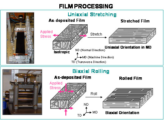
A very understandable explanation [6]
Thin film = Size reduction of bulk material in one dimension
Change of polymer molecule from "isotropic" Gaussian coil (spherical "ball") to elliptical form.
To put things even worse, electrostriction is a property of all dielectrics, regardless of their symmetry [5]. It produces a relatively small mechanical deformation under an applied electric field. Reversal of electric field does not reverse the direction of the deformation. If an electric field E is applied on a material, the electrostrictive strain x is defined by
Where Mijkl are components of the fourth-rank tensor and are called electrostrictive coefficients.
As its contribution to anisotropy is very difficult to formulate correctly, it is quite often ignored.
Ignoring also the effects of temperature and phase changes, another ignored little detail: Real world capacitor dielectrics are useless without a conductive foil or a metalized surface, at the interface between the dielectric and the conductor, can have air, among many other impurities, air tends to form bubbles and this is a great contributor to anisotropy.
However this should not be an issue for paper dielectrics, we already know that paper is permeable, but we also already know that paper is anisotropic. [7], [8]
But, what about polymers? Are they also permeable? It seems that yes they are. [9], [10]
Essential factors for permeation
. Free volume: In order for any molecules to move in a material there must be holes available.
. Continuous path through the polymer.
Polymer experts say that polymers look like a pile of tangles of spaghetti, following this food analogy, seems to me that a decent plate of spaghetti needs some cheese, with a lot of holes, maybe impurities would be the sauce, and the whole picture it is anything but isotropic.
Conclusion: Real world isotropic dielectrics are as real as Santa Klaus…
[1] Plamen I. Dankov (2010). Dielectric Anisotropy of Modern Microwave Substrates, Microwave and Millimeter Wave Technologies from Photonic Bandgap Devices to Antenna and Applications, Igor Minin (Ed.), ISBN: 978-953-7619-66-4, InTech, DOI: 10.5772/9061
[2] Senden, D.J.A. (2013). Strain Hardening and Anisotropy in Solid Polymers. Eindhoven: Technische Universiteit Eindhoven. ((Co-)promot.: prof.dr.ir. H.E.H. Meijer, dr.ir. L.E. Govaert & dr.ir. J.A.W. van Dommelen).
[3] Ellen M. Arruda, Mary C. Boyce. Evolution of Plastic Anisotropy in Amorphous Polymers during Finite Straining. Mechanical Engineering Department. Massachusetts Institute of Technology.
[4] T.B. v. Erp. Anisotropic plasticity in oriented semi-crystalline polymer systems.
Eindhoven University of Technology.
[5] Marko Budmir. Piezoelectric Anisotropy and Free Energy Instability in Classic Perovskites. École Polytechnique Fédérale de Lausanne.
(The relevant section about electrostriction was taken from another paper written about eight years before by Dragan Damjanovic.)
[6] Vorlesung/Lecture: Hans-Ulrich Krebs Polymer thin films. (Prof. Dr. Hans-Ulrich Krebs. Georg-August-Universität Göttingen. Institut für Materialphysik.)
[7] A. Kallmes, J. Scharcanski and C.T.J. Dodson. Uniformity and Anisotropy in Nonwoven Fibrous Materials.
[8] Yong-Joo Sung and Ramin Farnood. Characterizing Anisotropy of the Deterministic Features in Paper Structure with Wavelet Transforms. Department of Chemical and Applied Chemistry.University of Toronto. Toronto, Canada.
[9] Polymer permeability. Edited by J. Comyn, Elsevier Applied Science Publishers, London, 1985.
[10] P.M. Wood-Adams. Diffusion And Permeability In Polymers - Concordia University.
Part 3 – More Anisotropy
Isotropy is a difficult thing in the real world, to the point that even the vacuum isotropy is discussed today.
As well as Schrödinger's cat can not be, nor half-alive, neither half-dead, Schrödinger's mistress can not be half-pregnant.
If a material is infinitesimally anisotropic, then it cannot be isotropic.
But surprise!!! I have found some measurements!!! [1]
The dielectric anisotropy can be expressed as normalized ratios
∆Aε = 2 ∣ε’∥(ω) – ε’⊥(ω)∣ / [ε’∥(ω) + ε’⊥(ω)]
∆Atan(δ) = 2 ∣tan (δ∥) – tan (δ⊥)∣ / [tan (δ∥) + tan (δ⊥)]
Curiously, "practically isotropic" materials exhibit some degree of anisotropy, e.g.
i) PTFE, 0.945 mm thickness
∆Aε ≈ - 0.1 % ∆Atan(δ) ≈ - 4.0 %
ii) Polyolefin, 0.7725 mm thickness
∆Aε ≈ - 0.6 % ∆Atan(δ) ≈ 3.7 %
iii) Polycarbonate, 1.000 mm thickness
∆Aε ≈ 0.2 % ∆Atan(δ) ≈ - 4.0 %
iv) Polycarbonate Lexan® D-sheet, 0.51 mm thickness
∆Aε < 3 % ∆Atan(δ) < 11 %
Although author's effort on discredit his own measurements, this gives us a clue about what really happens with real world dielectrics. [2], [3], [4]
A picture is worth a thousand words
A bulk material can be "practically isotropic", "almost isotropic" or "isotropic by definition" or whatever, as can be seen on fig (a), unfortunately, industrial processes to obtain thin films leaves us on the situation shown on fig (b) or fig (c), i.e. biaxial anisotropy or uniaxial anisotropy, maybe here it can be seen more clearly
A very understandable explanation [6]
Thin film = Size reduction of bulk material in one dimension
Change of polymer molecule from "isotropic" Gaussian coil (spherical "ball") to elliptical form.
To put things even worse, electrostriction is a property of all dielectrics, regardless of their symmetry [5]. It produces a relatively small mechanical deformation under an applied electric field. Reversal of electric field does not reverse the direction of the deformation. If an electric field E is applied on a material, the electrostrictive strain x is defined by
xij = Mijkl Ek El
Where Mijkl are components of the fourth-rank tensor and are called electrostrictive coefficients.
As its contribution to anisotropy is very difficult to formulate correctly, it is quite often ignored.
Ignoring also the effects of temperature and phase changes, another ignored little detail: Real world capacitor dielectrics are useless without a conductive foil or a metalized surface, at the interface between the dielectric and the conductor, can have air, among many other impurities, air tends to form bubbles and this is a great contributor to anisotropy.
However this should not be an issue for paper dielectrics, we already know that paper is permeable, but we also already know that paper is anisotropic. [7], [8]
But, what about polymers? Are they also permeable? It seems that yes they are. [9], [10]
Essential factors for permeation
. Free volume: In order for any molecules to move in a material there must be holes available.
. Continuous path through the polymer.
Polymer experts say that polymers look like a pile of tangles of spaghetti, following this food analogy, seems to me that a decent plate of spaghetti needs some cheese, with a lot of holes, maybe impurities would be the sauce, and the whole picture it is anything but isotropic.
Conclusion: Real world isotropic dielectrics are as real as Santa Klaus…
[1] Plamen I. Dankov (2010). Dielectric Anisotropy of Modern Microwave Substrates, Microwave and Millimeter Wave Technologies from Photonic Bandgap Devices to Antenna and Applications, Igor Minin (Ed.), ISBN: 978-953-7619-66-4, InTech, DOI: 10.5772/9061
[2] Senden, D.J.A. (2013). Strain Hardening and Anisotropy in Solid Polymers. Eindhoven: Technische Universiteit Eindhoven. ((Co-)promot.: prof.dr.ir. H.E.H. Meijer, dr.ir. L.E. Govaert & dr.ir. J.A.W. van Dommelen).
[3] Ellen M. Arruda, Mary C. Boyce. Evolution of Plastic Anisotropy in Amorphous Polymers during Finite Straining. Mechanical Engineering Department. Massachusetts Institute of Technology.
[4] T.B. v. Erp. Anisotropic plasticity in oriented semi-crystalline polymer systems.
Eindhoven University of Technology.
[5] Marko Budmir. Piezoelectric Anisotropy and Free Energy Instability in Classic Perovskites. École Polytechnique Fédérale de Lausanne.
(The relevant section about electrostriction was taken from another paper written about eight years before by Dragan Damjanovic.)
[6] Vorlesung/Lecture: Hans-Ulrich Krebs Polymer thin films. (Prof. Dr. Hans-Ulrich Krebs. Georg-August-Universität Göttingen. Institut für Materialphysik.)
[7] A. Kallmes, J. Scharcanski and C.T.J. Dodson. Uniformity and Anisotropy in Nonwoven Fibrous Materials.
[8] Yong-Joo Sung and Ramin Farnood. Characterizing Anisotropy of the Deterministic Features in Paper Structure with Wavelet Transforms. Department of Chemical and Applied Chemistry.University of Toronto. Toronto, Canada.
[9] Polymer permeability. Edited by J. Comyn, Elsevier Applied Science Publishers, London, 1985.
[10] P.M. Wood-Adams. Diffusion And Permeability In Polymers - Concordia University.
Attachments


Last edited:
Dear SY
I respect and admire you, more than you can imagine, but this time you screwed up.
Please don't take this as anything personal against you, but only as a serious technical discussion.
Fortunately the laws of physics can't be broken; anisotropy and hysteresis are not unrelated phenomena.
Then, your "isotropic by definition" polymer, if really it is isotropic, hence cannot show hysteresis, conversely, if it shows hysteresis it can’t be isotropic.
Even more, I must answer by myself my own questions
Because, so far, you didn't explained the hysteresis phenomenon for isotropic materials, although result quite clear from my own rough demonstration(s), that this would be physically impossible.
Well, that is some progress, now you seems to accept some kind of anisotropy, but you are still ignoring real world capacitors.
That is for your ideal edge effects-free capacitors, filled into vacuum with an ideal dielectric which is perfectly isotropic along one axis.
Take a “block” of vacuum. Measure the properties “from face to face” in all three directions. Get back to me once you've done that.
I warn you that you will need an outstanding lab and struggle with gravitational field among other minor details.
No, I think it is the other way around, is you who confuse what happens on a bulk sample, "isotropic by definition" or rather "slightly anisotropic" with what happens in a real world thin film capacitor dielectric, under strain, pressure, temperature changes, phase changes, permeation, etc. that it is anisotropic by forming, among other things.
You're also, I believe, thinking through the consequences of the symmetry aspect, but ignoring elementary electrostatics.
You also forget, I believe, letting aside the different nature of fields, the fact that dielectric permittivity for decent dielectrics, is various orders of magnitude lower than magnetic permeability for ferromagnetic materials, hence the difficulties to measure dielectric anisotropy.
Finally, as I know that you love measurements, take your oscilloscope, your signal generator, and a capacitor, with a very simple circuit you can measure hysteresis, if you find hysteresis, not me, but physics, assures you that you are also measuring dielectric anisotropy.
If you can't find hysteresis, even with a large electric field, please tell us about such amazing isotropic hysteresis-free capacitor, I will be the first on the checkout line.
I respect and admire you, more than you can imagine, but this time you screwed up.
Please don't take this as anything personal against you, but only as a serious technical discussion.
Any amorphous polymer containing polar groups will be isotropic (by definition) yet show hysteresis to a greater or lesser degree.
Fortunately the laws of physics can't be broken; anisotropy and hysteresis are not unrelated phenomena.
Then, your "isotropic by definition" polymer, if really it is isotropic, hence cannot show hysteresis, conversely, if it shows hysteresis it can’t be isotropic.
Even more, I must answer by myself my own questions
Can you please explain to me how?
Because, so far, you didn't explained the hysteresis phenomenon for isotropic materials, although result quite clear from my own rough demonstration(s), that this would be physically impossible.
edit: And I should add that the rolling direction is normal to the applied field, so doesn't have much relevance to capacitor action.
Well, that is some progress, now you seems to accept some kind of anisotropy, but you are still ignoring real world capacitors.
That is for your ideal edge effects-free capacitors, filled into vacuum with an ideal dielectric which is perfectly isotropic along one axis.
Indeed, I agree that you would say that. Nonetheless, it's incorrect. Take a block of semicrystalline polymer. Measure the properties from face to face in all three directions. Get back to me once you've done that.
Take a “block” of vacuum. Measure the properties “from face to face” in all three directions. Get back to me once you've done that.
I warn you that you will need an outstanding lab and struggle with gravitational field among other minor details.
Your confusion, I think, is separating what happens on a microscopic, single domain level with what happens at a macroscopic level. You're also, I believe, not thinking through the consequences of the symmetry aspect- we only apply a field in the z direction.
No, I think it is the other way around, is you who confuse what happens on a bulk sample, "isotropic by definition" or rather "slightly anisotropic" with what happens in a real world thin film capacitor dielectric, under strain, pressure, temperature changes, phase changes, permeation, etc. that it is anisotropic by forming, among other things.
You're also, I believe, thinking through the consequences of the symmetry aspect, but ignoring elementary electrostatics.
You also forget, I believe, letting aside the different nature of fields, the fact that dielectric permittivity for decent dielectrics, is various orders of magnitude lower than magnetic permeability for ferromagnetic materials, hence the difficulties to measure dielectric anisotropy.
Finally, as I know that you love measurements, take your oscilloscope, your signal generator, and a capacitor, with a very simple circuit you can measure hysteresis, if you find hysteresis, not me, but physics, assures you that you are also measuring dielectric anisotropy.
If you can't find hysteresis, even with a large electric field, please tell us about such amazing isotropic hysteresis-free capacitor, I will be the first on the checkout line.
“Science is the belief in the ignorance of experts.” (Richard P. Feynman)
I must recognize that you are right, learning process never ends, and this forum is a clear example, every day one can learn something new.
However, I was right from the beginning; anisotropy and hysteresis are not unrelated phenomena.
The root of your confusion, I think, is that to study/understand physics, it is divided into “compartments”, e.g. Mechanics, Electrodynamics, Relativity, and a long etc.
However, Nature does not need to take classes at university, and physical phenomena occur in a more complex, regardless epistemological issue, reality flows as it is.
That is very laudable, but for the next time, please you try to not mislead yourself before confusing people with your own false assumptions/misunderstandings.
This is a serious accusation, but lacking any support.
Your mistake is almost as big as your obstinacy on insisting about it, if being a modest TV repairman removes me credibility, please talk with your colleagues, anybody who knows about condensed matter physics will tell you that those “facts” are wrong.
“Beware of false knowledge; it is more dangerous than ignorance.” (George B. Shaw)
Please, do not underestimate the readers, if you really want reducing potential confusion for them, I would say that, with all due respect, you should follow your own advice and try to understand a bit more basic physics before you pontificate about things that obviously you don't understand.
I must confess that I always enjoy your jokes and sarcasm, to the point of repeating by myself some of your jokes.
But desperation to repair a TV to put a meal on the table is not fun, poverty is not funny, so no need to be sarcastic with mine.
Just to clarify, I found such evidence on the web, as I already said on post#217, I thought it was understood, sorry.
The problem is, if I may be blunt, that on this issue you are not able to give all the correct answers, nobody can, and I don't want to be unkind with you, but your physics is almost as pathetic as my chemistry.
Finally, my favorite philosopher, said
You need to understand a bit more basic physics before you pontificate about capacitor size etc.
I must recognize that you are right, learning process never ends, and this forum is a clear example, every day one can learn something new.
However, I was right from the beginning; anisotropy and hysteresis are not unrelated phenomena.
The root of your confusion, I think, is that to study/understand physics, it is divided into “compartments”, e.g. Mechanics, Electrodynamics, Relativity, and a long etc.
However, Nature does not need to take classes at university, and physical phenomena occur in a more complex, regardless epistemological issue, reality flows as it is.
I am trying to correct errors put forth in a public forum, so others are not mislead.
That is very laudable, but for the next time, please you try to not mislead yourself before confusing people with your own false assumptions/misunderstandings.
A standard technique which seems to be used on here by some, including you, is to make an incorrect statement based on misunderstanding and then demand that others prove that it is untrue. This is not a helpful way to advance knowledge, or to acquire existing knowledge. I have told you, and others have told you, that anisotropy and hysteresis are unrelated phenomena. These are facts. It is for you to defend your speculation, not for us to prove you wrong. So far your defence has serious holes.
This is a serious accusation, but lacking any support.
Your mistake is almost as big as your obstinacy on insisting about it, if being a modest TV repairman removes me credibility, please talk with your colleagues, anybody who knows about condensed matter physics will tell you that those “facts” are wrong.
“Beware of false knowledge; it is more dangerous than ignorance.” (George B. Shaw)
I am not re-entering the 'debate', but merely reducing potential confusion for others who may read this thread.
Please, do not underestimate the readers, if you really want reducing potential confusion for them, I would say that, with all due respect, you should follow your own advice and try to understand a bit more basic physics before you pontificate about things that obviously you don't understand.
Let's see this evidence. It's odd that you can't afford basic distortion measurements, but you can afford the rather specialized equipment it takes to do measurements of mechanical, thermal, and optical anisotropy.
I must confess that I always enjoy your jokes and sarcasm, to the point of repeating by myself some of your jokes.
But desperation to repair a TV to put a meal on the table is not fun, poverty is not funny, so no need to be sarcastic with mine.
Just to clarify, I found such evidence on the web, as I already said on post#217, I thought it was understood, sorry.
The problem is, if I may be blunt, that you have to be willing to discard most of what you know that isn't so in order to build the knowledge base that it will take to understand what the correct answers are.
The problem is, if I may be blunt, that on this issue you are not able to give all the correct answers, nobody can, and I don't want to be unkind with you, but your physics is almost as pathetic as my chemistry.
Finally, my favorite philosopher, said
Attachments

A Short Digression on Linearity
Constitutive relation for dielectric media
For a perfectly isotropic and homogeneous dielectric becomes
With ε=constant, i.e. D=f(E) is a straight line, and the dielectric is said to be perfectly linear, so a capacitor will introduce no distortion at all.
Unfortunately, real world capacitors are not perfectly linear and they need a hysteretic (anisotropic) model for permittivity.
Using the results of post#301 we can write
A good indicator of linearity is to evaluate the ratio
The closer to zero, the closer is the ellipse to a straight line, then the greater linearity.
The area within hysteresis curve is
We must remember that for a capacitor, it is valid the approximation
Now we can see that a negligible voltage does not mean necessarily a negligible electric field across the capacitor, and it depends on its geometry, also we can write
It can be proved that, for the ellipse
Where a and b are the semi-major and semi-minor axes
For good dielectrics, dissipation factor is very low, and it is valid the approximation
Then
We can also compare linearity of two capacitors at the same frequency
Due to “difficulties conservation theorem”
Where
The parallel component, tan (δP) depends on the insulation resistance RP, as it is extremely high, this component is negligible.
The dielectric component, tan (δD) depends on the particular dielectric, in polypropylene capacitors it remains constant with frequency and will typically result in a value of about 10⁻⁴
The series component, tan (δS) is determined by the series resistance ESR, this component increases rapidly with frequency until it becomes dominant.
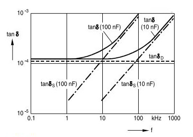
This illustrates the behavior of tan (δ) vs. measuring frequency, using two polypropylene capacitors of different capacitance as examples, and usually it is not shown on datasheets.
Then
We can compare different capacitors at the same frequency as
In order to compare parallel plate capacitors we must taking into account that, calling AD the dielectric area
Parallelepiped shape capacitors are made with many paralleled substructures, being n the number of paralleled substructures of thickness d
For metallized film capacitors, under the supposition that metallized thickness mi << di, calling the with of capacitor as WD, is valid the approximation
Then
Or
Now, finally we can write
Constitutive relation for dielectric media
Di = Doi + εij(ω) Ej
For a perfectly isotropic and homogeneous dielectric becomes
D = ε E
With ε=constant, i.e. D=f(E) is a straight line, and the dielectric is said to be perfectly linear, so a capacitor will introduce no distortion at all.
Unfortunately, real world capacitors are not perfectly linear and they need a hysteretic (anisotropic) model for permittivity.
Using the results of post#301 we can write
D = ∣ε(ω)∣ Eo cos (ω t - δ)
E = Eo cos (ω t)
ε(ω) = ε’(ω) + i ε’’(ω)
tan (δ) = ε”(ω) / ε’(ω)
ε(ω) =∣ε(ω)∣ [ cos (δ) + i sin (δ) ]
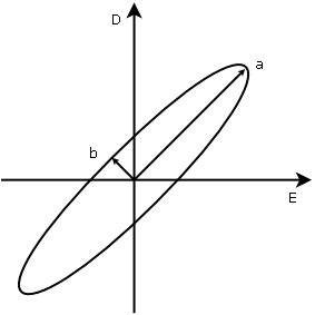
A good indicator of linearity is to evaluate the ratio
b/a
The closer to zero, the closer is the ellipse to a straight line, then the greater linearity.
The area within hysteresis curve is
A = ∮ D dE = ∮ (D dE/dt) dt = π ∣ε(ω)∣ Eo² ω sin (δ)
We must remember that for a capacitor, it is valid the approximation
E ≈ V/d
Now we can see that a negligible voltage does not mean necessarily a negligible electric field across the capacitor, and it depends on its geometry, also we can write
A ≈ π ∣ε(ω)∣ (V/d)² ω sin (δ)
It can be proved that, for the ellipse
A = π a b
Where a and b are the semi-major and semi-minor axes
a = Eo ω ≈ (V/d) ω
b = Eo∣ε(ω)∣ sin (δ) ≈ (V/d) ∣ε(ω)∣ sin (δ)
For good dielectrics, dissipation factor is very low, and it is valid the approximation
sin (δ) ≈ tan (δ)
Then
b ≈ (V/d) ∣ε(ω)∣ tan (δ)
b/a ≈ [∣ε(ω)∣ tan (δ)] / ω
We can also compare linearity of two capacitors at the same frequency
b1/a1 ≈ {[∣ε1(ω)∣ tan (δ1)] / [∣ε2(ω)∣ tan (δ2)]} (b2/a2) (*)
Due to “difficulties conservation theorem”
tan (δ) = tan (δP) + tan (δS) + tan (δD)
Where
tan (δP) = 1 / (RP ω C)
tan (δS) = ESR ω C
tan (δD) = Characteristic of the dielectric
The parallel component, tan (δP) depends on the insulation resistance RP, as it is extremely high, this component is negligible.
The dielectric component, tan (δD) depends on the particular dielectric, in polypropylene capacitors it remains constant with frequency and will typically result in a value of about 10⁻⁴
The series component, tan (δS) is determined by the series resistance ESR, this component increases rapidly with frequency until it becomes dominant.
This illustrates the behavior of tan (δ) vs. measuring frequency, using two polypropylene capacitors of different capacitance as examples, and usually it is not shown on datasheets.
Then
a ≈ (V/d) ω
b ≈ (V/d) ∣ε(ω)∣ ESR ω C
b/a ≈ ∣ε(ω)∣ ESR C
We can compare different capacitors at the same frequency as
a1 ≈ [(d2 C2) / (d1 C1)] a2
b1 ≈ [(d2 ε1 ESR1) / (d1 ε2 ESR2)] b2
b1/a1 ≈ [(ε1 C1 ESR1) / (ε2 C2 ESR2)] (b2/a2)
In order to compare parallel plate capacitors we must taking into account that, calling AD the dielectric area
C ≈ (ε AD) / (4πd)
Parallelepiped shape capacitors are made with many paralleled substructures, being n the number of paralleled substructures of thickness d
Ci ≈ ni (εi ADi) / (4πdi)
For metallized film capacitors, under the supposition that metallized thickness mi << di, calling the with of capacitor as WD, is valid the approximation
WDi ≈ ni di
Then
(d2/d1)² ≈ (ε2 AD2 WD2 C1) / (ε1 AD1 WD1 C2)
d2/d1 ≈ [(ε2 VD2 C1) / (ε1 VD1 C2)]½
Now, finally we can write
a1 ≈ [(ε2 VD2 C2) / (ε1 VD1 C1)]½ a2
b1 ≈ [(ε1 VD2 C1) / (ε2 VD1 C2)]½ (ESR1 / ESR2) b2
b1/a1 ≈ [(ε1 C1 ESR1) / (ε2 C2 ESR2)] (b2/a2)
Attachments


Last edited:
Some loose ends
1) Just as an example, with some MKP capacitors like those I use in my amps, they are: C1=3.3 μF 450 VDC (Epcos B32674D4335 15.0 mm.x24.5 mm.x31.5 mm.) and C2=6.8 μF 450 VDC (Epcos B32674D4685 22.0 mm.x36.5 mm.x31.5 mm.)
This is illustrated on the following graph, with coordinate system placed to show the point more clearly.
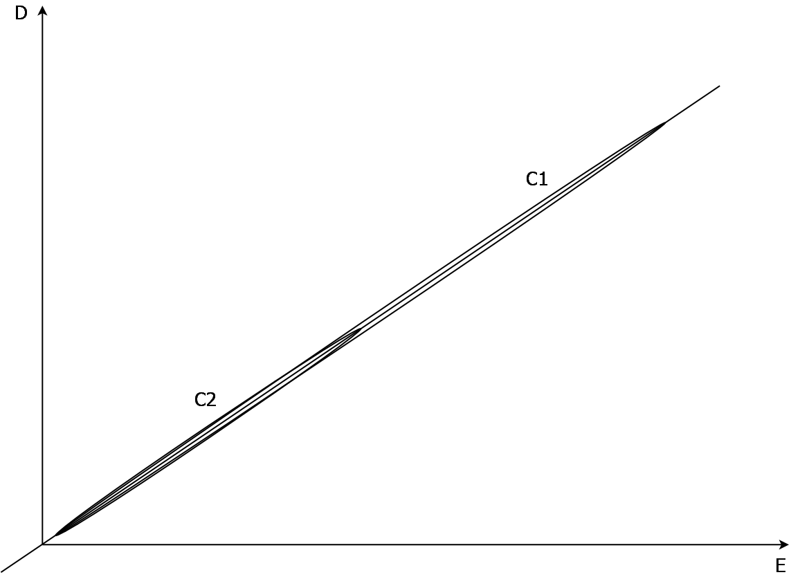
Differences on linearity are small, but still favoring the smaller capacitor.
2) Same type MKP capacitors with almost the same volume: C1=4.7 μF 300 VDC (Epcos B32674F3475 14.0 mm.x24.5 mm.x31.5 mm.) and C2=4.7 μF 300 VDC (Epcos B32676F3475 12.0 mm.x22.0 mm.x42 mm.)
C1 is slightly more linear than C2.
Parallelepiped shape capacitors are made with many paralleled substructures and this tends to reduce ESR, and even it can vary substantially up to a factor 2 or more with pin diameter and material, as capacitance increases, pin diameter often increases too and dielectric thickness often decreases, then can occur that ESR decreases with capacitance, so it is needed an analysis for each particular case.
If you want to use big capacitors, this is the way you go, cheap industrial grade MKP capacitors.
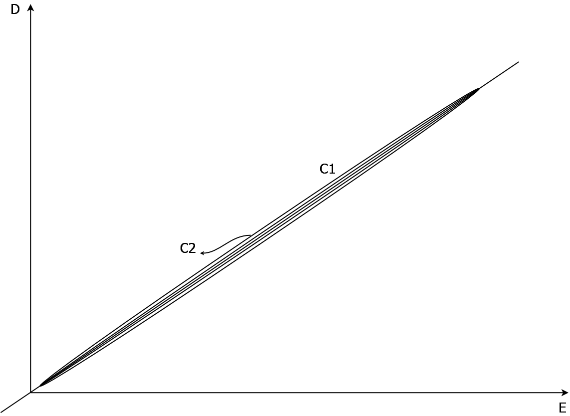
3) I found these cylindrical MKP capacitors that seems to have similar d, C1=35 μF 700 VDC (Vishay GLI 700-35) and C2=230 μF 700 VDC (Vishay GLI 700-230)

As can be seen, C1 is more linear than C2 by far.
No surprises here, no paralleled substructures, and connectors are very large, then, this capacitor geometry is more predictable.
Conclusion
On previous post Eq.(*) roughly proved that capacitor linearity depends on the dielectric and its losses, due to dielectric anisotropy, i.e. real world capacitors are far from being ideal, and statements like this just sit the basis for another audio myth
This is wrong, it is not the voltage across the capacitor that matters, but the electric field E, even more, doing the math you can see for yourself with almost any datasheet, that my original guess is quite correct.
Let me continue "armchair theorizing", but as I have no data for polystyrene capacitor, I will use those from a 100 nF MKP, if you don’t mind.
C1=100 nF 630 VDC (Solen SM010)
C2=10000 μF 10 VDC (Vishay 54103E3)
Then
This is so horrible that I don’t know how draw it…
Hysteresis loop for C2 is so nonlinear that seems a rotated ellipse, it should be rotated a little because ε2 > ε1, but for clarity it isn’t, both loops start at the same point, and "major" axes of both ellipses lie on the same line, then “rotation” is an effect of extreme nonlinearity, be in mind that both V1 and V2 have the same phase.
To my regret, I must admit that audiofools, sometimes can be right, i.e. capacitor quality does matter, and the bad reputation of electrolytic capacitors is well deserved, and if you can't measure the difference, your instruments must be worse than mine.
1) Just as an example, with some MKP capacitors like those I use in my amps, they are: C1=3.3 μF 450 VDC (Epcos B32674D4335 15.0 mm.x24.5 mm.x31.5 mm.) and C2=6.8 μF 450 VDC (Epcos B32674D4685 22.0 mm.x36.5 mm.x31.5 mm.)
a1 ≈ 2.12 a2
b1 ≈ 0.88 b2
This is illustrated on the following graph, with coordinate system placed to show the point more clearly.
Differences on linearity are small, but still favoring the smaller capacitor.
b1/a1 ≈ 0.41 (b2/a2)
2) Same type MKP capacitors with almost the same volume: C1=4.7 μF 300 VDC (Epcos B32674F3475 14.0 mm.x24.5 mm.x31.5 mm.) and C2=4.7 μF 300 VDC (Epcos B32676F3475 12.0 mm.x22.0 mm.x42 mm.)
a1 ≈ a2
b1 ≈ 0.52 b2
C1 is slightly more linear than C2.
b1/a1 ≈ 0.52 (b2/a2)
Parallelepiped shape capacitors are made with many paralleled substructures and this tends to reduce ESR, and even it can vary substantially up to a factor 2 or more with pin diameter and material, as capacitance increases, pin diameter often increases too and dielectric thickness often decreases, then can occur that ESR decreases with capacitance, so it is needed an analysis for each particular case.
If you want to use big capacitors, this is the way you go, cheap industrial grade MKP capacitors.
3) I found these cylindrical MKP capacitors that seems to have similar d, C1=35 μF 700 VDC (Vishay GLI 700-35) and C2=230 μF 700 VDC (Vishay GLI 700-230)
a1 ≈ 6.67 a2
b1 ≈ 0.5 b2
As can be seen, C1 is more linear than C2 by far.
b1/a1 ≈ 0.075 (b2/a2)
No surprises here, no paralleled substructures, and connectors are very large, then, this capacitor geometry is more predictable.
Conclusion
On previous post Eq.(*) roughly proved that capacitor linearity depends on the dielectric and its losses, due to dielectric anisotropy, i.e. real world capacitors are far from being ideal, and statements like this just sit the basis for another audio myth
In a given circuit, using a bigger capacitor will result in less distortion, not more, because the signal voltage across the cap will be reduced.
This is wrong, it is not the voltage across the capacitor that matters, but the electric field E, even more, doing the math you can see for yourself with almost any datasheet, that my original guess is quite correct.
Armchair theorizing is all very well, but your claims simply do not stand up again the real world evidence, which conclusively shows that the bigger the capacitor, the lower distortion. Take a 100nF polystyrene capacitor and put it up against a 10000uF electrolytic, and you won't be able to measure the distortion either way.
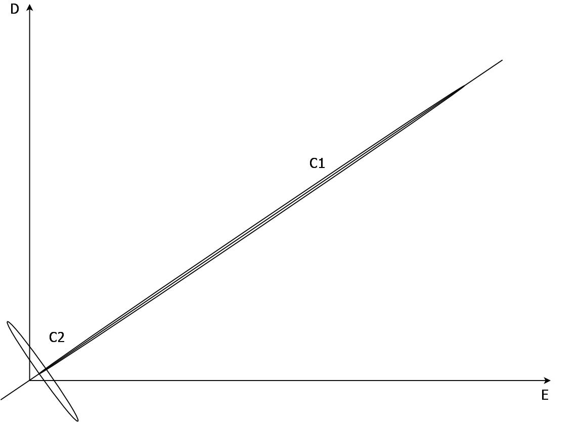
Let me continue "armchair theorizing", but as I have no data for polystyrene capacitor, I will use those from a 100 nF MKP, if you don’t mind.
C1=100 nF 630 VDC (Solen SM010)
tan (δ1) ≈ 9 x 10⁻⁵, ε1 ≈ 2.1, d1 ≈ 6 μm, V1 = V, ω = 100 Hz
C2=10000 μF 10 VDC (Vishay 54103E3)
tan (δ2) ≈ 0.31, ε2 ≈ 8, d2 ≈ 0.015 μm, V2 ≈ V x 10⁻⁵, ω = 100 Hz
Then
a1 ≈ 250 a2
b1 ≈ 0.019 b2
This is so horrible that I don’t know how draw it…
Hysteresis loop for C2 is so nonlinear that seems a rotated ellipse, it should be rotated a little because ε2 > ε1, but for clarity it isn’t, both loops start at the same point, and "major" axes of both ellipses lie on the same line, then “rotation” is an effect of extreme nonlinearity, be in mind that both V1 and V2 have the same phase.
b1/a1 ≈ 7.6 x 10⁻⁵ (b2/a2)
To my regret, I must admit that audiofools, sometimes can be right, i.e. capacitor quality does matter, and the bad reputation of electrolytic capacitors is well deserved, and if you can't measure the difference, your instruments must be worse than mine.
Attachments


Last edited:
- Status
- Not open for further replies.
- Home
- Member Areas
- The Lounge
- ECC82/12AU7 Line Preamp